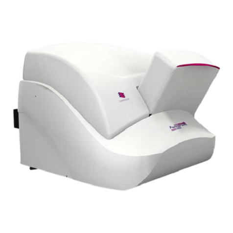
3D Histech P1000 User manual

P1000 SERVICE SOFTWARE MANUAL
SERVICE GUIDE
JANUARY 13, 2020
3DHISTECH
[Cég címe]

P1000 SERVICE SOFTWARE MANUAL
DISCLAIMER
SERVICE GUIDE
1
Disclaimer
Copyright © 2001-2020 3DHISTECH Ltd.
All rights reserved.
Intellectual property related to the 3DHISTECH products are as
follows:
EP 1,789,831; US 7,663,078; EP 2,024,772; JP 2009-512685; US
12/301,781; EP 1,644,767; JP 2007-516451; US7,327,515; EP
1,994,398; JP 2008-557835; US 12/281,566; U0700210; US
6,246,785; HU0900142; HU0700404; PCT/HU2007/000065; EP
08762668.5; US 12/663,537; PCT/AT2006/000492; JP 2008-542552;
EP 06817469; US 12/095,545; PCT/AT2006/000493; EP 06817470.5;
US 12/095,596; HU0900741; US 61/264,732; US 11/826,752;
P0401870; PCT/IB2005/050344; US 11/662,976; HU0700409; US
12/042,050; US 77/636,144 and 007502032.
The above-mentioned granted patents, granted utility model,
registered trademarks, pending international and national patent
applications and the other corresponding IP are the sole properties
of the 3DHISTECH Ltd.
3DHISTECH Ltd. is not liable for damage of whatever nature
(including, but not limited to, general or specific damage, indirect
damage, consequential damage or incidental damage, including
the results of the analysis of the digitized slides, for example,
change of health status related to erroneous diagnosis from the
digitized slide(s)) that stems from or is associated with use of
Product, digitized slides, quality of staining, quality of stained
slides, quality of used method of staining. 3DHISTECH Ltd.
assumes no responsibility for the functionality and fault-free
condition of your “application programs” (Workflows, VBA
macros, Commander scripts).
CAUTION
For research and education uses only, not for use in diagnostic
procedures. This product has not been approved or cleared as a
medical device by the U.S. Food and Drug Administration, nor any
other regulatory authority. The data and images obtained or
viewed using this product are not intended for clinical or diagnostic
use.
For performance evaluation only, the performance characteristics
of this product have not been established.
Third-party disclaimer
3DHISTECH Ltd. is not liable for damage of whatever nature
(including, but not limited to, general or specific damage, indirect
damage, consequential damage or incidental damage, including
damage resulting from lost profits, interruption of business, loss of
business information, pecuniary loss or similar damage) that stems
from or is associated with the incorporated part of this Product
that is made by a third-party company.
THE SOFTWARE IS PROVIDED “AS IS” AND WITHOUT WARRANTY
OF ANY KIND, EXPRESSED, IMPLIED OR OTHERWISE, INCLUDING
WITHOUT LIMITATION, ANY WARRANTY OF MERCHANTABILITY
OR FITNESS FOR A PARTICULAR PURPOSE.

P1000 SERVICE SOFTWARE MANUAL
FONT TYPES AND SYMBOLS
SERVICE GUIDE
3
Font Types and Symbols
Example
Words or characters that appear on the screen.
These include field names, screen and window titles,
push-buttons and menu names, functions or
options.
Keys on the keyboard. For example, function keys
(such as F11) or the Ctrl+M key combination.
Example
Cross-references within the document or to other
documents.
Warning!
It might cause irreversible damage or harm to the
user of the product or the product itself if this
instruction is not followed.
Caution!
It might cause the product to not work properly if
this instruction is not followed and alerts to a
potential danger situation.
Note:
Calls Caution to some important features.
[RB1] megjegyzést írt: A Terms and Abbreviation
egyelőre teljesen irreleváns fejezet, ezért kivettem.
Ha úgy döntünk, hogy szükség van rá és lesz hozzá
releváns tartalom, természetesen visszateszem.

P1000 SERVICE SOFTWARE MANUAL
1. STARTING THE SERVICE SOFTWARE
4
SERVICE GUIDE
1. Starting the Service Software
1. Find the MicroscopeConfiguration.xml file in the folder below:
C:\\ProgramData\3DHISTECH\SideScanner\
2. Open it with some word processing software (for example,
Notepad).
3. Find the following line: <HardvarLayer Virtual=”False”
Type=Type_3”/>.
4. Modify the text with green background to Type_1 to activate service
mode.
Warning!
If more than one Instructor or Administrator operates at
the same time on the same virtual surface, they can erase, cancel, or
modify each others' savings.
5. Start the .exe file from the folder below:
C:\\Program Files\3DHISTECH\SlideScanner\MicroscopeService.exe
6. Enter the service password 'seristen'.
7. Click the Create new control profile button to create a new control
profile.
8. Set preset to 'P1000Prototype' and enter the serial number of the
instrument.
9. After using the software, reset Type_1 to Type_3.

P1000 SERVICE SOFTWARE MANUAL
2. DEFAULT DIRECTIONS OF THE (ROBOTIC) ARM
SERVICE GUIDE
5
2. Default Directions of the (Robotic) Arm
X
Y
Z
0
FIGURE 1(ROBOTIC)ARM

P1000 SERVICE SOFTWARE MANUAL
2. DEFAULT DIRECTIONS OF THE (ROBOTIC) ARM
6
SERVICE GUIDE
X
Y
Z
[FF2] megjegyzést írt: Hiányoznak az irány jelölő nyilak

P1000 SERVICE SOFTWARE MANUAL
3. MAIN USER INTERFACE
SERVICE GUIDE
7
3. Main User Interface
Type of current scanner, serial number
and CAN bus display
Components bar
Enter data window
Component control panels
List firmware of current
scanner
Create new control profile
Save/cancel
settings
FIGURE 3MAIN USER INTERFACE

P1000 SERVICE SOFTWARE MANUAL
4. USER INTERFACES AND FUNCTIONALITIES OF MOTOR/COMPONENT CONTROL
PANELS
8
SERVICE GUIDE
4. User Interfaces and Functionalities of Motor/Component Control Panels
Name of
motor/component
Stepping unit, the distance the motor covers by
one click (0,01-100.000).
For security reasons, start with the lowest value
stepping up gradually.
Positive, negative
navigation by the defined
step values
Caution!
The arrows do not
necessarily show the
direction of physical
movement!
Go to II
Navigates the
motor/component to the
position defined by the
Aperture motor position
value. (0.85µm in this
case).
Home: Finds the motor
zero position.
Finds (if applicable):
1. Magnet of Hall sensor
motors
2. Zero sign of metric gauge
3. Home position value of
absolute metric gauge
Set value
Writes the Pos field value
to Aperture motor
position field.
Go to I
Navigates the motor/
component to the
position defined in Pos
field.
The Pos field has double
functionality: displays
current position after
navigation or target
position can be defined.
FIGURE 4SIDE PANEL AND APERTURE HIGH LEVEL SETUP
[FF3] megjegyzést írt: Home fülön a tördelés nem az
igazi a 3 pontnál

P1000 SERVICE SOFTWARE MANUAL
4. USER INTERFACES AND FUNCTIONALITIES OF MOTOR/COMPONENT CONTROL
PANELS
SERVICE GUIDE
9
The operation of the Arm control panel is the same as the motor’s one.
1. By adjusting the Resolution slide, you can set the distance covered by the unit by one click.
2. The operation of arrows is consistent with what they show.
Caution!
The arrows do not necessarily show the direction of physical movement!
Resolution slide
X, Y, Z navigation of the Arm
Go to position defined in X,
Y, Z fields
Current position after
navigation
Mark double or single-wide
slides
Open/close Gripper arm
+
+
+
FIGURE 5ALL NAVIGATION OPTIONS OF THE ARM

P1000 SERVICE SOFTWARE MANUAL
4. USER INTERFACES AND FUNCTIONALITIES OF MOTOR/COMPONENT CONTROL
PANELS
10
SERVICE GUIDE
3. In the X-Y-Z fields, the post-navigation positions are displayed but you can enter any values. Click the Go to button to send the unit to the required
position.
4. Click the related button to use the Gripper for either single or double-wide slide. Depending on which the active button is, click the Open/Close
button to set the Gripper to the defined value.
5. The Home button navigates the Slide loader 3D unit to zero position on all axes.
Keyboard control:
The components can be navigated using the keyboard, too. Some functionalities have their related buttons. Using a keyboard is useful when
the operator must physically approach P1000 as much as software operation is not adequate. It is recommended to use a wireless keyboard for
such operations. The volume + an –buttons of some keyboards can be used to adjust resolution, too.
-X
+X
+Y
-Y
-Z
+Z
Gripper
Close
Open
Set
value
Resolution
Save icon
The Save icon on the right of the description suggests saving your work at this point to prevent loss of work.
[RT4] megjegyzést írt: Kimaradt egy d

P1000 SERVICE SOFTWARE MANUAL
5. COMPONENTS PANE
SERVICE GUIDE
11
5. Components Pane
List and functional test of Sensors
List and test the operation of Step motors
List and test Cameras, image preview
Adjust and test condenser Aperture
Adjust and test ND filter
Select Objective, change and test Objective positions
(requires 40x objective)
Adjust the Arm and Gripper hardware limits, define and
test the Safety Z position of the Arm
Adjust and test Stage hardware limits
Adjust Slide loading unit, synchronize with other
components, define and set Stage loading position
Synchronize Objectives, Apertures and Filters
Note
Functionalities depending on each other are
highlighted on Components pane while noninitialized
functionalities are inactive.
[RT5] megjegyzést írt: Nekem elforgatva jelenik meg.

P1000 SERVICE SOFTWARE MANUAL
6. SENSORS
12
SERVICE GUIDE
6. Sensors
1. When clicking the Initialization button, the software starts to communicate with all sensors. If all sensors reply, initialization is successful.
Initialization
Low level setup
Validation/Testing
l
s
Save/cancel settings
Status window
Sensors available for
testing
l
s

P1000 SERVICE SOFTWARE MANUAL
6. SENSORS
SERVICE GUIDE
13
2. After initialization, click the Validation/Testing button. As Turn on/off sensors does not work currently, activate sensors according to the description
below.
3. After validation, click the Step motors menu, and then, the Turn on/off sensors button in the Validation/Sensors menu activates. As a result, the
sensors can be controlled manually.
4. Slide edge
4.1. After turning on the sensor, the electronics on the Arm is activated.
4.2. The operation of the sensor can be validated blocking the laser beam by hand
and moving it near. As a result, the displayed value must be changing. Tuning
of the sensor is described later.
5. Slide out
5.1. After turning on, the operation led lights up.
5.2. There are three states of the led: prism on, prism off, uncertain. Tuning of the
sensor is described later.
Handle the laser
sensors with
extra attention!
Prism on
Prism off
Uncertain

P1000 SERVICE SOFTWARE MANUAL
6. SENSORS
14
SERVICE GUIDE
6. Door button
6.1. The door button can be found in the right-bottom corner of P1000. The door cannot be opened until the Arm goes to Arm Safety position. For
validation, select in the drop-down menu and turn on the Turn on/off sensors button. Box zero indicates the state of the door button.
6.2. After pushing the button, the box gets cleared and activates again after clicking the Get sensor raw data button.
7. Door opening
7.1. You can test here the interlocks. Checkbox 0 indicates the state of the service interlock and checkbox 1 indicates the state of the sliding door
interlock.

P1000 SERVICE SOFTWARE MANUAL
6. SENSORS
SERVICE GUIDE
15
7.2. The test procedure requires an interlock pin. The related box signs when the pin is removed.

P1000 SERVICE SOFTWARE MANUAL
6. SENSORS
16
SERVICE GUIDE
8. Magazine holder 0,1,2,3,4
8.1. You can test the micro switches of the holder here signing either the presence or the lack of the magazines. The tests can be carried out holding
the switches.
Switches of double magazine racks: 8,9,10,11,24,25,26,27
Switches of single magazine racks: 8,9,10,11,12,13,14,15,16,17

P1000 SERVICE SOFTWARE MANUAL
6. SENSORS
SERVICE GUIDE
17
8.2. Numbers belonging to each magazine:
9. Validate the results and save.
Double
Magazine
Number
1
8
2
9
3
10
4
11
5
24
6
25
7
26
8
27
Single
Magazine
Number
Magazine
Number
1
8
2
9
3
10
4
11
5
12
6
13
7
14
8
15
9
16
10
17

P1000 SERVICE SOFTWARE MANUAL
7. STEP MOTORS
18
SERVICE GUIDE
7. Step motors
1. This chapter describes the operation of step motors and the related encoder with which P1000 is equipped.

P1000 SERVICE SOFTWARE MANUAL
7. STEP MOTORS
SERVICE GUIDE
19
2. On the Step motors low level setup page, most parameters are pre-defined and cannot be changed. The Home (Zero position) button state is
also pre-defined, however, it can be turned on and off.
Warning!
Do not change its state because the system starts finding the sensor or value in zero position the opposite direction which is false operation and
P1000 can be seriously damaged!
3. On the Step motors testing page, you can find the functions as illustrated below.
Caution!
Speed and Acceleration values can be changed but do not change them!
After clicking the Start motor and Test motor buttons, a green tick appears in the drop-down list next to the actual motor showing its proper
functioning.
Table of contents
Other 3D Histech Laboratory Equipment manuals
3D Histech
3D Histech Pannoramic DESK User manual

3D Histech
3D Histech Pannoramic MIDI User manual

3D Histech
3D Histech Pannoramic 250 FLASH II User manual
3D Histech
3D Histech TMA Grand Master 2.0 User manual
3D Histech
3D Histech PANNORAMIC CONFOCAL 3.0.3 User manual

3D Histech
3D Histech TMA Grand Master 2.6 User manual

3D Histech
3D Histech PANNORAMIC DESK DW II 3.0.4 User manual

3D Histech
3D Histech TMA Grand Master 3.2 User manual

3D Histech
3D Histech Pannoramic DESK User manual
3D Histech
3D Histech Pannoramic DESK II User manual