3M 725 User manual

User’s Guide
3M™Wrist Strap Monitor Model 725

1
Index
Section Page
Safety Information..................................................................................... 2
1 Theory of Operation.................................................................................. 4
2 Operating Your System.............................................................................. 6
3 Installation When Attaching to a Static Control Work Surface................. 7
4 Installation Under Work Bench................................................................. 8
5 Installation Using 3M™ Belt Clip Model 723............................................ 9
6 Parking Clip .............................................................................................. 9
7 Battery Replacement ............................................................................... 10
8 Verification Procedure for the 3M™ Wrist Strap Monitor Model 725 ..... 10
9 Specifications .......................................................................................... 12
10 Parts Included.......................................................................................... 12
11 Required Accessories and Optional Available Parts................................ 13
12 Additional Wrist Strap Monitoring Information ..................................... 14
13 Warranty.................................................................................................. 15

2
SAFETY INFORMATION
Please read, understand, and follow all safety information contained in this
User’s Guide prior to the use of this 3M™Wrist Strap Monitor Model 725.
Retain these instructions for future reference.
Intended Use:
The 3M Wrist Strap Monitor Model 725 is designed to monitor the operation
of a wrist strap grounding system for a single operator. This product has been
designed and tested for use with 3M™Dual Conductor Wrist Straps and 3M™
Work Surfaces Grounding Systems. This unit is powered by a 9 volt alkaline
battery. Use of other components or use in any other application not evaluated
by 3M may cause improper performance and/or an unsafe condition. To avoid
damage to the 3M Wrist Strap Monitor Model 725, do not use this monitor
outside of the operating conditions listed in this user’s guide.
Explanation of Symbols
CAUTION
Operator(s) Wrist Strap Assembly Ground
Work Surface Ground
Earth; ground
Power input connector polarity (center negative)
Explanation of Signal Word Consequences
WARNING Indicates a potentially hazardous situation which, if not avoided, could
result in death or serious injury and/or property damage.
CAUTION Indicates a potentially hazardous situation which, if not avoided, may
result in minor or moderate injury and/or property damage.
NOTICE Indicates a situation which, if not avoided, could result in property damage.

3
WARNING
To reduce the risks associated with medical device malfunction which, if not avoided, could result in
serious injury or death:
• Persons with active implanted medical devices (such as heart pacemaker devices) should never
use this monitor.
CAUTION
To reduce the risks associated with environmental contamination which, if not avoided, could result in
minor or moderate injury:
• Dispose of monitor in accordance with all applicable local and government regulations.
NOTICE
To prevent damage to the 3M™Wrist Strap Monitor Model 725:
• Users should not attempt to service this device.
• Do not use in wet or humid environments.
To reduce the risk of damage to components or assemblies being handled:
• Always properly ground your tools and dissipative surfaces to known good ground before
connecting the Wrist Strap Monitor Model 725 for monitoring. If unsure of suitable ground,
contact a licensed electrician before installation.
• Always ensure operator grounding during use of monitor. The Wrist Strap Monitor Model 725
does not provide grounding.
ENVIRONMENTAL CONDITIONS
This equipment has been tested and found to be safe to operate within these environmental conditions.
This is not a warranty of equipment performance within these conditions.
• Indoor use only
• Ingress Protection: IPX0
• Altitude: Up to 2,000 m
• Pollution degree 2.
• Temperature: Maximum 110°F / 43°C Minimum 50°F / 10°C
• Humidity: Maximum relative humidity 80% for temperatures up to 31°C decreasing linearly to
50% relative humidity at 40°C .

4
Figure 1 – 3MTM Wrist Strap Monitor Model 725 with 3MTM
Dual Conductor Wrist Strap Assemblies.
3MTM Dual Conductor
Metal Wrist Strap*
3MTM
Dual Conductor
Fabric Wrist Strap*
3MTM Wrist Strap
Monitor Model 725
SECTION 1
Theory of Operation
(Refer to Figure 1)
The 3M™Wrist Strap Monitor Model 725 is designed to monitor the operation of
the wrist strap grounding system of a single operator. The system features special
wrist bands and ground cords that contain two independent conductors.*
The
Wrist Strap Monitor Model 725
performs a resistance measurement by
applying an electrical current of less than 1 μA. The path for the current is through
one conductor of the wrist strap ground cord that contains a current-limiting resistor,
through one side of the wrist band, through the skin of the wearer under the band,
through the second side of the wrist band, through the second conductor of the wrist
strap ground cord that contains a current limiting resistor, and finally back to the
monitor. If the resistance of the wrist strap loop is less than 35 megohms**, the wrist
strap ground cord, wrist band, and the interface of the wrist band to the arm of the
wearer are considered to be functioning correctly. If the measured resistance is over
35 megohms**, a red lamp flashes along with a chirping audible alarm
.
In addition, the Wrist Strap Monitor Model 725 monitors the ground clip
connection to a predetermined electrical ground. This is accomplished by
measuring the resistance from the monitor, through one conductor of the monitor’s
ground cord and metal clip, through the ground point conducting medium, through
the other metal clip and conductor of the monitor’s ground cord, and finally back
to the Wrist Strap Monitor Model 725. If the resistance of this loop exceeds 10
megohms***, a red lamp will illuminate with a continuous audible alarm. This
indicates that there is a problem with the monitor’s ground cord or the ground
point connection.
*3M™
Dual Conductor Cord & Wrist Band are required for use with
the 3M™
Wrist Strap Monitor Model 725, ordered separately.
** Resistance values are ±15%
*** Resistance values are +15%, -50%

5
The
3M™
Wrist Strap Monitor Model 725 requires only a small amount of current to operate.
When the red lamp and the audible alarm are activated simultaneously, the monitor requires
approximately 5 μA of current. When the lamp and alarm are not activated (normal condition),
the monitor requires approximately 50 μA of current.
As with any battery operated electronic device, the life
of the battery will be determined by the frequency of
use. However, for the Wrist Strap Monitor Model 725
you can expect a battery life of approximately one year
in continuous operation under normal conditions.
Note: Use an alkaline battery for longer life.
The Wrist Strap Monitor Model 725 monitors
the battery voltage and alerts the operator when it is necessary to change the
battery. When the battery voltage falls below 6 volts the red lamp will illuminate
with no audible alarm. At this time the Wrist Strap Monitor Model 725 is still
operational, making reliable resistance measurements of the wrist strap assembly
and the ground connection.
Voltage on Operator when Connected to the 3M Wrist Strap Monitor
Model 725
There is a concern about the voltage that is applied to an operator while they are connected
to a monitor. Some of today’s electronic components are extremely sensitive to electrostatic
discharge from a person (less than 10 volts). The following chart for the Wrist Strap Monitor
Model 725 illustrates the level of voltage that will appear on the operator under various
resistance conditions.
Voltage on Operator when connected to the Wrist Strap Monitor Model 725
Condition Observed Voltage
No Skin Resistance 0.8V
200K Ohm Skin Resistance 0.9V
Likely Case Before Alarm 3.5V
Worst Case Before Alarm 6.8V
Absolute Worst Case 9.0V
NOTICE
The 3M™Wrist Strap Monitor
Model 725 does not have the
capability of verifying that the
ground point is a suitable ground.
If you are not sure what a suitable
ground is, contact a licensed
electrician before installation.
Note: For more information about wrist strap monitoring see Additional Wrist Strap Monitoring
Information (Section 12).

6
SECTION 2
Operating Your System
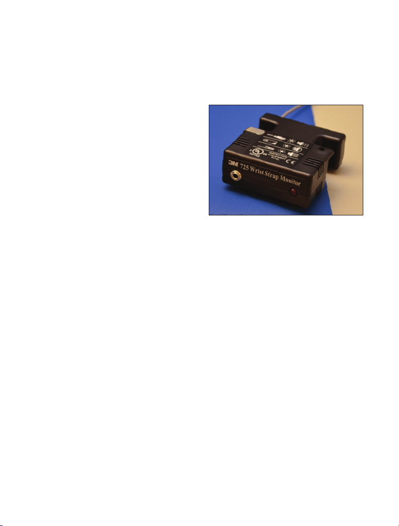
To operate the 3M™Wrist Strap Monitor Model 725, attach the monitor’s (6 ft.)
ground cord with dual conductor ground clip to a suitable ground.
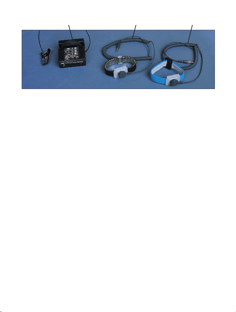
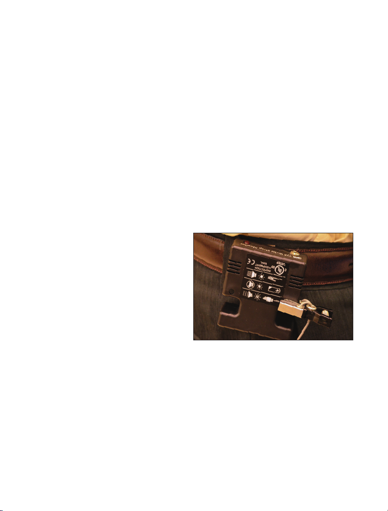
Attach a 3M™Dual Conductor Ground
Cord to a 3M™Dual Conductor Wrist
Band. Place the wrist band on your
wrist and plug the cord into the jack
on the front of the Wrist Strap Monitor
Model 725. Plugging into the jack
activates the monitor and causes it to
emit a short beep and the red lamp
to momentarily flash. If the red lamp
flashes with an intermittent audible
alarm or at any time during use, the
resistance of the wrist strap assembly
is greater than 35 megohms.** If
the red lamp and the audible alarm
remain on continuously, check the dual
conductor ground clip connection.
The system is now ready for use.
**Resistance values are ±15%
Note: Operators may complain that the alarm
is sounding too often until they learn to
adjust the wrist band to fit securely or apply
an approved skin moisturizer on a frequent
basis. Please remember that the monitor is
informing you that the operator is exceeding
the established static control requirement for
resistance to ground when wearing a static
protective wrist strap assembly. These alarms
alert the operator when sensitive electronics
are possibly being exposed to static electricity.
Prior to incorporating the wrist strap monitor
into your static control process, the operator
could be unaware of these events.
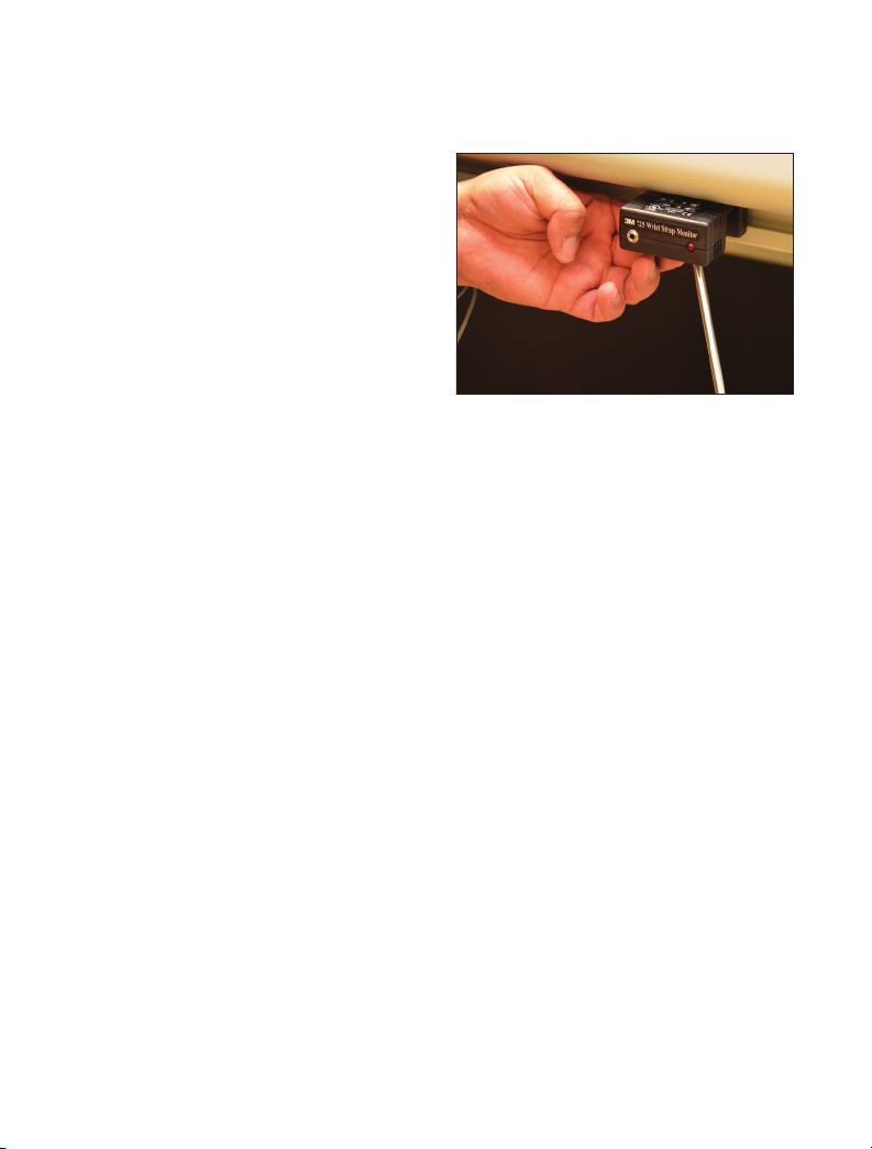
Figure 2
NOTICE
If you decide not to use the dual
conductor ground clip that is attached
to the monitor’s ground cord in the
way described in this user instruction
manual, observe the following
precaution: Attach each of the two wires
of the monitor’s ground cord to separate
ground bonding points. By attaching the
wires to the same ground but at different
physical locations, the monitor can
check for loose or lost connections.

7
SECTION 3
Installation When Attaching to a Static Control Work Surface
The 3M™Wrist Strap Monitor Model 725 can be used to ground a work surface
while providing a monitored grounding point for an operator. To ground a
work surface, the Wrist Strap Monitor
Model 725 contains a snap located
on its bottom cover, that is connected
internally to the monitor’s ground cord.
To use this feature there must be a 3M™
Female Snap Fastener Model 3034,
10 mm, snap fastener attached to the
grounding layer of the work surface.
Simply align the male snap on the
monitor with the female snap on the
work surface and press downward on
the monitor. The work surface is now
automatically grounded through a one
megohm resistor by the Wrist Strap
Monitor Model 725.
3M™Work Surface 8200 Series use the female 10 mm (3M Female Snap
Fastener Model 3050) snap fastener for grounding. 3M™ Work Surfaces 1800,
8300 and 8800 Series use the female 10 mm (3M Female Snap Fastener Model
3034) snap fastener for grounding. In addition all 3M™Portable Field Service
Kits 8500 Series include the 10 mm (Female Snap Fastener Model 3034) snap
fastener.
Use of an optional 3M™Stand-By Jack 3057 at the work station extends the life
of the monitor’s input jack. The user disconnects the wrist strap ground cord
from the wrist band and plugs into the Stand-By Jack 3057 which is mounted at
the work station. Plugging into the Stand-By Jack 3057 prevents the Wrist Strap
Monitor Model 725 from continuously alarming when disconnected from the
wrist band.
The system is now ready for use.
Note: Although the work surface is grounded by
the 3M™Wrist Strap Monitor Model 725, it is
not monitoring the ground to the work surface.
Figure 3

8
SECTION 4
Installation Under Work Bench
The 3M™Wrist Strap Monitor Model
725 can be mounted under a work bench
by securing with two #8 screws (not
supplied) through the mounting hole
tabs located on the top cover.
When mounting the Wrist Strap Monitor
Model 725 under a work bench for non
mobile use, remove the parking clip
(Section 6) from the Wrist Strap Monitor
Model 725 using a small screwdriver.
The Wrist Strap Monitor Model 725 is
now ready to mount.
Position the monitor so that it is
convenient for the operator to plug
their wrist strap ground cord into the
jack on the front of the monitor. It is
recommended that the front face of the monitor be flush or slightly recessed
from the front edge of the work bench. Attach the monitor to the work bench
with the screws. It may be necessary to pre-drill pilot holes for the screws.
Attach the dual conductor ground clip or each wire of the monitor’s dual
conductor ground cord to a suitable ground.
Use of an optional 3M™Stand-By Jack 3057 at the work station extends the life
of the monitor’s input jack. The user disconnects the wrist strap ground cord
from the wrist band and plugs into the Stand-By Jack 3057 which is mounted at
the work station. Plugging into the Stand-By Jack 3057 prevents the Wrist Strap
Monitor Model 725 from continuously alarming when disconnected from the
wrist band.
The system is now ready for use.
Note: Use of the monitor in this way precludes
grounding a work surface through the snap
connector on the bottom of the monitor. A static
control work surface, if present, would require
grounding separately through an additional
ground cord.
Figure 4

9
SECTION 5
Installation Using 3M
™
Belt Clip 723 (Optional)
An optional belt clip is available to further enhance the portability feature of
the 3M™Wrist Strap Monitor Model 725. This expands the use of the monitor
when operators need to be highly mobile as in an electronic manufacturing
environment. Simply attach the belt clip with female snap connector to the
male snap connector on the monitor bottom cover. Slide the clip over your
belt in a convenient place, so that the wrist strap ground cord will not interfere
with normal body movements when attached to the monitor. Attach the dual
conductor ground clip to a suitable ground at the work location. During mobility,
attach the dual conductor ground clip to the parking clip on the Wrist Strap
Monitor Model 725 (See Section 6).
SECTION 6
Parking Clip
A parking clip is supplied
with the Wrist Strap Monitor
Model 725 allowing mobile
users to silence the ground clip
disconnect alarm. Attaching the
dual conductor ground clip to the
parking clip prevents unnecessary
disconnecting/connecting of the
wrist strap ground cord from the
input jack during mobility. An
added benefit of this feature is that
it extends the life of the dual conductor ground cord plug and the monitor’s input
jack. The parking clip is already attached to the mounting tab of the Wrist Strap
Monitor Model 725. If the Wrist Strap Monitor Model 725 is to be mounted
under a work bench for permanent use, remove the parking clip from the Wrist
Strap Monitor Model 725 using a small screwdriver.
Figure 5

10
SECTION 7
Battery Replacement
When only the red lamp illuminates
on the 3M™Wrist Strap Monitor
Model 725, it is time to change
the battery. Unplug the wrist strap
ground cord from the Wrist Strap
Monitor Model 725 jack before
proceeding. Remove the top cover
of the Wrist Strap Monitor Model
725 case by squeezing the two tabs
(grooved area located on the bottom
cover) inward while lifting the top
cover. Remove the used battery
carefully by using a pulling-twisting motion to unsnap the battery from the
connectors on the printed circuit board.
Install a new 9 volt alkaline battery by supporting the snap connectors on the
printed circuit board with your fingers, while using a pushing-twisting motion to
fully seat the terminals of the battery into the snap connectors.
Note: Use an alkaline battery for longer life.
Pass the monitor’s ground cord through one of the two exit wire slots in the
bottom half of the case. Align the rear locking tab on the top cover, to the tab
slot on the bottom cover while maintaining the ground cord in the desired wire
slot. Rotate the top cover downward onto the two side locking tabs of the bottom
cover and snap firmly into place.
SECTION 8
Verification Procedure for the 3M Wrist Strap Monitor Model 725
The Wrist Strap Monitor Model 725 cannot be recalibrated after the initial
factory calibration. However, the following steps can be used to determine if the
Wrist Strap Monitor Model 725 is operating within its specifications.
Figure 6

11
Equipment Needed
• Resistance Substitution Box (RSB), 1 Ohm to 45 Megohms ± 1%.
• One two-conductor cable with standard 3.5 mm (miniature) phone plug attached
on one end and appropriate connectors on the other end to connect to RSB.
• Two single conductor wires with clip style on one end and appropriate
connectors on the other end to connect to a RSB.
Note: Two conductor cables must have an isolation resistance of >1 Gigohm between conductors.
Two separated wires may also be used to obtain higher isolation resistance.
Procedure
a) Install a new 9 volt battery into the 3M™ Wrist Strap Monitor Model 725.
b) Short the dual conductor ground clip by attaching to a conductive metal
object such as a coin.
c) Plug the phone jack test cord into the wrist strap jack on the front of the
monitor and attach the other end of the cord to the RSB.
Set the RSB as follows and observe the lamp and audible alarm:
•29.8 Megohms – Red lamp OFF, audible alarm OFF.
•40.2 Megohms – Red lamp ON (Flashing), audible alarm ON
(Chirping).
d) Connect the two single conductor wires to the RSB. Attach the other ends
of the wires with clips to the metal jaws of the Wrist Strap Monitor Model
725 dual conductor ground clip. Be sure to prevent the clips from contacting
each other. Plug in the phone jack test cord into the wrist strap jack on the
front of the monitor and short the opposite ends together.
Set the RSB as follows and observe the lamp and audible alarm:
•5.0 Megohms – Red lamp OFF, audible alarm OFF.
•11.5 Megohms – Red lamp ON (Continuous), audible alarm ON
(Continuous tone).

12
3MTM Wrist Strap Monitor
Model 725 Size
2.5 x 2.6 x 1.1 in.
(6.4 x 6.6 x 2.8cm)
Accuracy +/-15%
Test Voltage 9 VDC Open circuit
Test Current Less than 1 microamp
Power Supply Requirements 9 Volt alkaline battery recommended
(Not supplied)
Environmental
Operating Conditions
Temperature:
Maximum
: 110°F / 43°C
Minimum
: 50°F / 10°C
Humidity:
Maximum relative humidity 75%
SECTION 9
Specifications
SECTION 10
Parts Included
1 ea. Wrist Strap Monitor Model 725 with 6 ft. dual conductor ground cord/clip and parking clip.
1 ea. User’s Guide & Verification Procedure

13
* Includes Band & Cord
Only accessories, optional parts and replacement parts supplied or specified by
3M Company shall be used with this product.
Use only a clean dry cloth to clean the 3M™Wrist Strap Monitor Model 725.
For Repair & Service Center:
11705 Research Boulevard, Building 1, Austin, TX 78759
Phone: (800) 426-8688 press #2
SECTION 11
Required Accessories and Optional Available Parts
Model No. Description Size
2368 3M™ Dual Conductor Fabric Wrist Band adjustable
2381 3M™ Dual Conductor Metal Wrist Strap* small
2382 3M™ Dual Conductor Metal Wrist Strap* medium
2383 3M™ Dual Conductor Metal Wrist Strap* large
2384 3M™ Dual Conductor Metal Wrist Band small
2385 3M™ Dual Conductor Metal Wrist Band medium
2386 3M™ Dual Conductor Metal Wrist Band large
2360 3M™ Dual Conductor Coil Cord 5 ft. (1.5m)
2370 3M™ Dual Conductor Coil Cord 10 ft. (3.0m)
2371 3M™ Dual Conductor Coil Cord 20 ft. (6.1m)
3057 3M™ Stand-By Jack 1.9 x 1.3 x 1.1 in. (4.8 x 3.3 x 2.8cm)
723 3M™ Belt Clip

14
SECTION 12
Additional Wrist Strap Monitoring Information
Suggested reading on wrist strap requirements and wrist strap monitoring:
• EIA 625 - Requirements for Handling Electrostatic-Discharge- Sensitive
(ESDS) Devices.
• EN100015/1 - Protection of Electrostatic Sensitive Devices.
• 3M Tech. Response #123 - Pulsed Current vs. Constant Current in Work
Station Monitors.
• 3M Static Digest Issue No.1, 1998 - Disc Drive Industry - Static Control
Considerations.
Note: The 3M references are available by calling 3M Electronic Solutions Division Customer
Service Department at 1-866-722-3736.

3
Electronic Solutions Division
Static Control Products
926 JR Industrial Drive
Sanford, NC 27332-9733
Toll-Free: 866-722-3736
International: 919-718-0000
Email: [email protected]
www.3Mstatic.com
Please recycle. Printed in USA.
© 3M 2014. All rights reserved.
78-9101-9994-8 JHA
SECTION 13
Important Notice
All statements, technical information, and recommendations related to 3M’s
products are based on information believed to be reliable, but the accuracy or
completeness is not guaranteed. Before using this product, you must evaluate
it and determine if it is suitable for your intended application. You assume all
risks and liability associated with such use. Any statements related to the product
which are not contained in 3M’s current publications, or any contrary statements
contained on your purchase order shall have no force or effect unless expressly
agreed upon, in writing, by an authorized officer of 3M.
Warranty; Limited Remedy; Limited Liability.
This product will be free from defects in material and manufacture for a period
of one year from time of purchase. 3M MAKES NO OTHER WARRANTIES
INCLUDING, BUT NOT LIMITED TO, ANY IMPLIED WARRANTY OF
MERCHANTABILITY OR FITNESS FOR A P ARTICULAR PURPOSE.
If this product is defective within the warranty period stated above, your exclusive
remedy shall be, at 3M’s option, to replace or repair the 3M product or refund the
purchase price of the 3M product. Except where prohibited by law, 3M will not
be liable for any indirect, special, incidental or consequential loss or damage
arising from this 3M product, regardless of the legal theory asserted.
Other manuals for 725
1
Table of contents
Other 3M Measuring Instrument manuals