3M 10 User manual

3M™Pressure Feed HVLP & LVLP Spray
Gun Owner’s Manual
Alimentación por Presión de 3M™
Pistola aplicadora en spray HVLP (Alto
Volumen Baja Presión) y LVLP (Bajo
Volumen Baja Presión) Manual del
Usuario
Read Warnings and Instructions
Lea las Instrucciones y Advertencias
This Manual Covers Spray Gun Models 10, 11, 12S, 12SZ, 14, 15, 19 and 19C
Este Manual Cubre los Modelos Pistolas aplicadora en spray 10, 11, 12S, 12SZ, 14, 15,
19 y 19C
3

1
3
Table of Contents
Topic Page Number
Safety Statements .................................................................................................... 2
Contents-Unpacking ................................................................................................. 7
General Set Up and Spray Gun Use ........................................................................... 9
Spray Gun Care and Cleaning.................................................................................. 11
Spray Gun Parts Identification Series 10 & 14 ........................................................ 14
Spray Gun Parts Identification Series 11 & 15 ......................................................... 16
Spray Gun Parts Identification Series 12S .............................................................. 18
Spray Gun Parts Identification Series 12SZ.............................................................. 20
Spray Gun Parts Identification Series 19.................................................................. 22
Spray Gun Parts Identification Series 19C ............................................................... 24
Tip/Nozzle/Air Cap Selection Guide ......................................................................... 26
Troubleshooting ...................................................................................................... 28
Tema Número de Página
Medidas de Seguridad ............................................................................................ 31
Contenidos-Desempaque........................................................................................ 36
Instalación y Uso General del Pistola aplicadora en spray........................................ 37
Cuidado y Limpieza del Pistola aplicadora en spray................................................. 40
Identificación de Piezas de Pistola aplicadora en sprayes Series 10 y 14 ................ 44
Identificación de Piezas de Pistola aplicadora en sprayes Series 11 y 15 ................ 46
Identificación de Piezas de los Pistola aplicadora en sprayes Serie 12S .................. 48
Identificación de Piezas de los Pistola aplicadora en sprayes Serie 12SZ ................ 50
Identificación de Piezas de los Pistola aplicadora en sprayes Serie 19 .................... 52
Identificación de Piezas de los Pistola aplicadora en sprayes Serie 19C .................. 54
Guía de Selección de la Punta/Boquilla/Tapa del Aire .............................................. 56
Solución de problemas ........................................................................................... 58
Tabla de Contenidos

2 3
3
WARNING
To reduce the risks associated with all residual hazards:
• Read, understand, follow and retain for future reference all safety statements in
each applicable equipment owner’s manual and refer to the applicable Material
Safety Data Sheet & material container label for each material to be sprayed
before using your 3M equipment.
• This equipment is to be used only by professionals familiar with the possible
applicable safety hazards.
• Do not use this product around unsupervised children.
• Never modify any part of this product.
• Always comply with local, state and national codes governing ventilation, fire
protection, operation, maintenance, housekeeping and disposal plus all safety
statements in applicable owner manuals, MSDS and material container labels.
To reduce the risks associated with chemical exposure:
• Check spray equipment for damage and proper function before use. Repair/
replace worn, damaged or malfunctioning components.
• Always wear appropriate, approved personal protective equipment for eye,
skin, respiratory and hearing protection per the applicable MSDS and material
container labels at all times when spraying.
To reduce the risks associated with fire and explosion:
• Must maintain adequate ventilation per applicable MSDS and material container
labels for each material being sprayed in the work area.
• All ignition sources such as smoking must be kept out of the spray area.
• Always maintain a readily available, approved fire extinguisher or other approved
fire fighting equipment in the spray area.
• Always locate air compressor or turbine unit as far away from spray area as the
air supply hoses allow.
• Never use solvents containing Methylene Chloride and Trichloromethane for any
reason to avoid a possible violent, explosive chemical reaction when exposed to
aluminum or zinc (refer to the manufacturer's MSDS or contact material supplier
if there is any doubt to confirm compatibility).
3M™ Pressure Feed HVLP & LVLP Spray Gun Safety Statements
Read, understand and follow all safety information contained in these
instructions prior to set up and operation of any 3M™ Pressure Feed HVLP &
LVLP Spray Gun. Retain these instructions for future reference. Refer to the
applicable Material Safety Data Sheet and material container label for each
material to be sprayed before using this 3M equipment.
Intended Use:
Each 3M™ Pressure Feed HVLP & LVLP Spray Gun is intended for use by professionals
who are familiar with the possible applicable safety hazards. They are intended to
deliver the desired production speed and finish quality for all commonly used coatings.
The spray gun must be set up as specified in the 3M™ Pressure Feed HVLP &
LVLP Spray Gun Owner’s Manual. It has not been evaluated for other uses.
Explanation Of Signal Word Consequences
Indicates a hazardous situation, which, if not avoided, could result
in death or serious injury.
Indicates a hazardous situation, which, if not avoided, could result
in minor or moderate injury.
Explanation of Product Safety Label Symbols
Attention: Read accompanying documentation
CAUTION:
WARNING:

4 5
3
EC Declaration of Conformity
Company Name
3M Company
Company Address
Automotive Aftermarket Division
3M Center, Building 251
St Paul, MN USA 55144-1000
Declares that the products:
Product name and or Model number
3M™ Pressure Feed Spray Guns Series 10, 11, 12S, 12SZ, 14, 15, 19, 19C
3M™ Gravity Feed Spray Guns Series 05-100, 05-300, 07, 07HS, 10G, 10GP
Type and/or Description
Pressure Feed and Gravity Feed Spray Guns
Conforms to the following specifications:
Directives
Machinery Directive (2006/42/EC) and the essential health and safety requirements
Standards
EN ISO 12100-1:2003 Safety of machinery. Basic concepts, general principles for design
– Basic terminology, methodology
EN ISO 12100-2:2003 Safety of machinery. Basic concepts, general principles for design
–Technical principles
Year in which CE mark first affixed
2008
Full Name of responsible person.
Kurt Beinlich Position: Technical Director
Signature: Date:
CAUTION
To reduce the risks associated with lifting and handling:
• Always follow proper lifting and handling practices when moving system
components.
To reduce the risks associated with tripping, falling and tipping:
• Route air hoses and any extension cords away from traffic areas, sharp edges,
moving parts and hot surfaces. Do not pull on air hoses to move the compressor
or turbine unit.
To reduce the risks associated with hazardous air pressure:
• Maintain spray equipment per 3M care and cleaning instructions in the applicable
owner's manual.
• Ensure air input pressure and all applicator system regulators are properly
adjusted prior to each use.
• Always follow required air pressure relief procedures for relieving air pressure
from the unit.
To reduce the risks associated with sharp point:
• If using a turbine unit, do not touch the air hose connection coil relief spring.
To reduce the risks associated with compression spring release:
• Maintain a firm grip on fluid adjustment knob when removing.
To reduce the risks associated with environmental contamination:
• Spray materials, solvents, other cleaning materials and electronic components
must be disposed of per federal, state and local regulations.

6 7
3
Unpacking
Remove the components from the box. Inspect for concealed damage and/or missing
items. If you discover any damage and/or missing pieces, contact your distributor
immediately.
Your 3M™ Pressure Feed HVLP & LVLP Spray Gun Kit includes:
• Spray Gun
• Care Kit
• Cup (optional)
3M™ Series 10 & 14 HVLP Spray Guns
The 3M™ Series 10 & 14 HVLP Spray Guns are non-bleed
spray guns with a composite body construction, 10 cfm air
consumption, 1:1 reduction ratio, 3/4” air inlet connection:
10 psi maximum inlet air pressure*, for use with either
compressed air systems or turbines equipped with a pressure
relief mechanism. Air stops flowing through the series 10 & 14
spray guns when the trigger is fully released.
3M™ Series 11 & 15 HVLP Spray Guns
The 3M™ Series 11 & 15 HVLP Spray Guns are bleeder
spray guns with a composite body construction, 10 cfm air
consumption, 1:1 reduction ratio, 3/4” air inlet connection:
10 psi maximum inlet air pressure*, for use with turbine air
systems only. The series 11 & 15 spray guns are a free flow
design, which allows air to flow through the spray guns even
after the trigger is released.
3M™ Series 12S HVLP Spray Gun
The 3M™ Series 12S HVLP Spray Gun is a non-bleed
spray gun with a composite body construction, 10 cfm air
consumption, 6:1 reduction ratio, 1/4” air inlet connection: 60
psi maximum inlet air pressure*, for use with compressed air
systems only.
* Maximum inlet pressure will yield approximately 10 psi at the air cap.
Spray Gun Overview
3M spray guns were designed from the inside out for the effective, efficient, economical
application of paints, adhesives, coatings and finishes. These spray guns deliver large
spray patterns with very low overspray. The soft, tight, adjustable pattern with complete
atomization results in a high finish quality and absolute control. Each light weight
spray gun is designed for easy handling, reliability and durability and for minimum
maintenance costs.
Whether your air source is compressed air or a turbine unit, you will benefit from the
speed of application, the decrease in masking, sanding and cleanup time and the
ability to achieve a fine finish. Combine your 3M spray gun with the 3M™ PPS™ Paint
Preparation System and enjoy additional savings of time and cleaning solvents.
3M equipment is for professional use only. Hazards can occur from equipment misuse.
Any misuse of the equipment or accessories, such as over pressurizing, modifying
parts, using incompatible chemicals and fluids, or using worn or damaged parts can
cause serious bodily injury, fire, explosion or property damage. Please read and follow
all Safety Statements and Instructions.
Contents

8 9
3
Adjusting the Fluid Flow
The fluid flow can be adjusted by using
the needle adjustment screw as noted
in Fig. 1. As a starting point, gently turn
the knob clockwise until you have very
little needle travel (pull trigger to verify).
Do not over-tighten. After the needle
travel has stopped, further tightening will
only serve to compress the spring and
will not aid in adjustment. Next turn the
knob counterclockwise two full turns.
These adjustment procedures will serve
only as a starting point. Fine tuning of
these adjustments will be based on your
material and technique.
Fig. 1
Needle Adjustment Screw
General Set Up and Spray Gun Use
For additional instructions refer to your cup or fluid source manual.
Note: Flush the spray gun before using
Fluid hose Hard Cup PPS H/O Cup
3M™ Series 12SZ HVLP Spray Gun
The 3M™ Series 12SZ HVLP Spray Gun offers all the features
and benefits of the series 12S Spray Gun with a composite
body construction, 10 cfm air consumption, 6:1 reduction
ratio, 1/4” air inlet connection; 60 psi maximum inlet air
pressure*, and the ability to spray organic and inorganic zinc
materials.
All wetted parts are made of a non-stick composite
material with graphite packing.
3M™ Series 19 HVLP Spray Gun
The 3M™ Series 19 HVLP Spray Gun is a non-bleed spray
gun with an aluminum body with a non-sticky, 10 cfm air
consumption, 4.3:1 reduction ratio, 1/4” air inlet connection:
43 psi maximum inlet air pressure* for use with compressed
air system.
3M™ Series 19C LVLP Spray Gun
The 3M™ Series 19C LVLP Spray Gun offers the same
features of the 3M™ Series 19 HVLP Spray Gun with an
aluminum body with a non-stick, solvent resistant finish,
4.5 cfm air consumption, 4.3:1 reduction ratio, 1/4” air inlet
connection: 43 psi maximum inlet* air pressure and the added
benefit of low cfm air consumption allowing for use with even
small portable air compressors.
Contents cont.
* Maximum inlet pressure will yield approximately 10 psi at the air cap.

10 11
3
Relieve the pressure from the spray
gun and cup before servicing.
1. Turn off the air supply to the
spray gun.
2. Disconnect air line from the
spray gun.
3. Pull trigger to return mix to spray
gun cap.
General System Maintenance
Do not immerse the spray gun in solvent.
Spray Gun Care and Cleaning
Do not wipe the spray gun with a cloth
soaked in solvent; ring out the excess.
Note: Your spray gun may be made
from aluminum and may contain
aluminum components. Certain
solvents containing Methylene
Chloride and Tricloromethane are
not chemically compatible with
aluminum.
Read, understand and follow all
safety statements as well as wear
appropriate, approved personal
protective equipment per the
applicable MSDS and material
container labels for cleaning
solutions.
You must lubricate the moving
components after every cleaning of the
spray gun. Cleaning washes away the
lubricants that protect the friction points.
Use an appropriate lubricant such as
petroleum jelly.
Do not use metal tools to clean the air
cap holes as this may scratch them;
scratches can distort the spray pattern.
Do not point the spray gun up while
cleaning it.
Lubricate
Lubricate
Lubricate
HVLP Lubricate
Fig. 2
Fan Adjustment Knob
Adjusting the Fan Pattern Size
The fan size is regulated by the fan
adjustment knob as noted in Fig. 2.
As a starting point, gently turn the
knob clockwise until you feel no
further adjustment. Next, turn the knob
counter-clockwise one full rotation. The
fan adjustment will allow you to spray
from a small round to a full fan pattern.
The pattern can also be changed from
vertical to horizontal by rotating the air
cap a ¼ turn.
General Set Up and Spray Gun Use cont.
WRONG
RIGHT
Spray Technique
1. To achieve the best results when
spraying material, keep the spray
gun perpendicular to the surface and
maintain a consistent distance of
approximately 6 to 8 inches
(160-200 mm) from the object being
sprayed.
2. Use smooth, even strokes across the
surface to be sprayed with 50% over-lap.
3. Paint using parallel strokes. This
technique applies all coatings evenly
without cross coating.
Horizontal Pattern
Vertical Pattern
Right
90º 6” - 8”
Note: The small round pattern can
be achieved by closing down the fan
adjustment, triggering the gun lightly,
and maintaining a distance from your
target of 2 to 4 inches (50-100 mm).

12 13
3
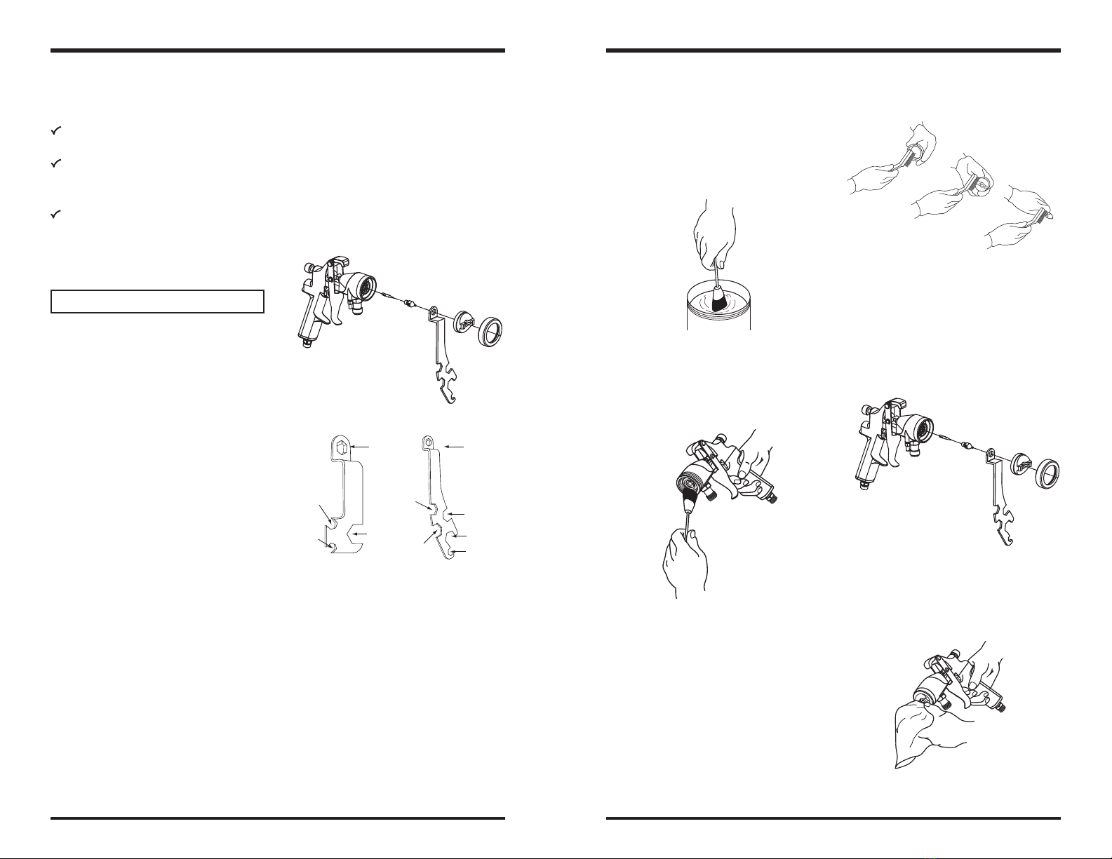
11. Thread fluid needle tip on finger
tight. Pull trigger back and hold
while you install the fluid nozzle with
the gun wrench. Tighten the nozzle
securely to obtain a good seal.
12. Install the retaining ring and air cap.
Spray Gun Care and Cleaning cont.
10. Scrub the retaining ring, air cap and
fluid nozzle with a soft-bristle brush.
To clean out air cap holes, use a
small brush. Clean the air cap and
fluid nozzle after each use. Do not
soak the retaining ring in solvent for
prolonged periods of time.
13. Dampen a soft cloth with solvent
and wring-out the excess. Point
the spray gun down and wipe off
the outside of the spray gun.
9. With the spray gun pointed down,
clean the front of the spray gun,
using a soft-bristle brush and
solvent.
8. Dip the end of a soft-bristle brush
into a compatible solvent. Do not
continuously soak the brush’s bristles
with solvent, and do not use a wire
brush.
Fluid
Nozzle Fluid
Nozzle
Valve Cap
Cup Hex
Fitting
Cup Hex
Fitting
Packing Nut
Seal
Housing
Fan Air
Fitting
Packing
Nut
Pressure
Stem
ATTENTION
Solvent left in the spray gun air
passages could result in a poor quality
paint finish. Do not use any cleaning
method which may allow solvent into the
spray gun air passages. Do not expose
air regulators and gauges to solvent as
damage may occur.
Cleaning Process
1. Relieve the pressure from the spray
gun and cup before servicing.
2. Refer to your cup or fluid source
manual for removal and cleaning.
3. To retain unused material or
temporarily store mixed material,
see your Local, State, Federal and
OSHA guidelines, along with material
manufacturer’s recommendations for
storage.
4. Flush the spray gun. To flush spray
gun, run water or compatible and
compliant solvent into the spray gun
fluid passage while triggering the
spray gun.
Spray Gun Care and Cleaning cont.
5. Remove the retaining ring and air cap.
6. Pull trigger back and hold while
removing the fluid nozzle from the
spray gun with the gun wrench.
Note: This prevents damage to the
needle tip and fluid nozzle.
Clean the fluid and air line filters daily.
Check for any fluid leakage from the
spray gun and fluid hoses.
Flush the spray gun before changing
colors and when done operating the
spray gun.
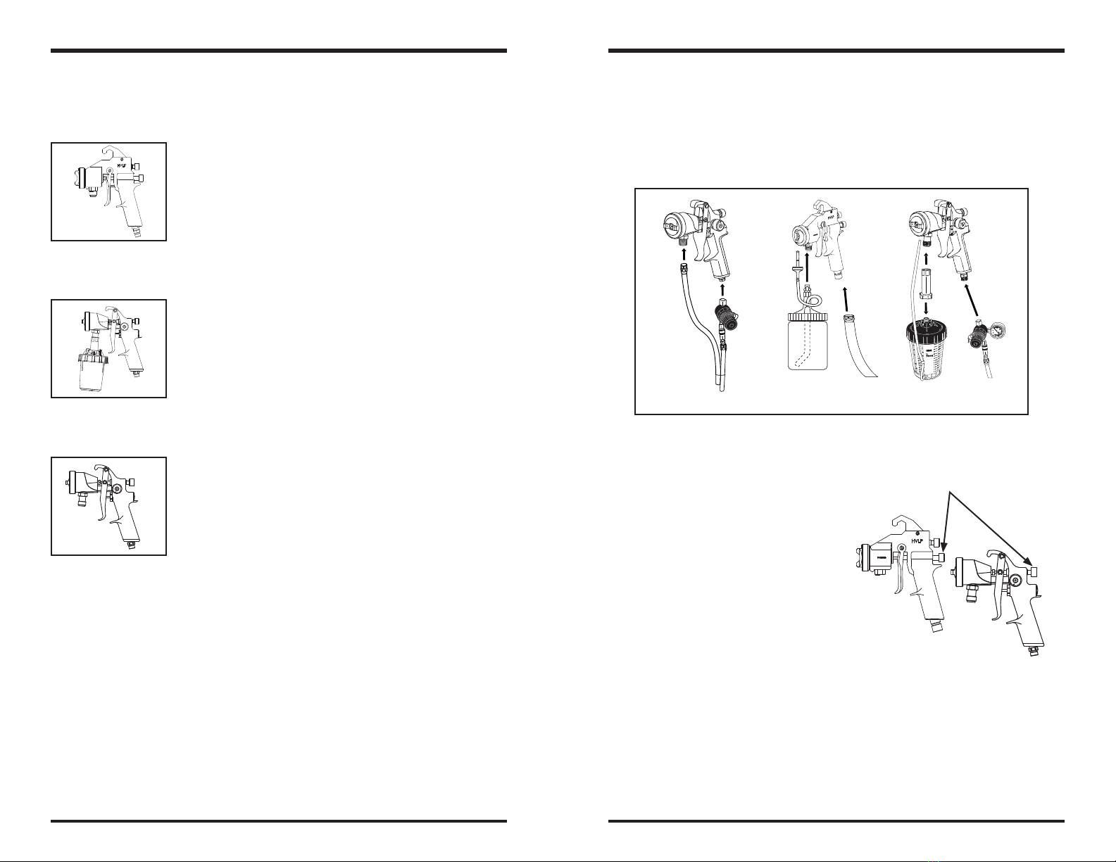
Wrench for composite
handle spray gun
Wrench for metal
handle spray gun
7. Release the trigger and unscrew the
fluid needle tip with fingers.

14 15
3
3M™ Series 10 & 14 Spray Gun Parts Identification 3M™ Series 10 & 14 Spray Gun Parts Identification
Item Description Replacement PN
1 Retaining Ring 91-043
2 Air Cap (Composite) 91-009-XXX
2* Air Cap (Aluminum) 91-071-XXX
3 Fluid Nozzle 91-143-XXXDT**
4 Closure Ring
5 O-Ring
6 Fluid Passage (Series 10) 91-064
6* Fluid Passage (Series 14) 91-203
7 O-Ring
8 O-Ring UH-1405/10 (Pack of 10)
9 Needle Guide 91-202/2 (Pack of 2)
10 Compression Spring 91-199/3 (Pack of 3)
11 Packing Nut 91-201
12 Right-Half Spray Gun Handle
13 3/8” Screw UH-769/4 (Pack of 4)
14 1/4” Screw
15 Spray Gun Hook
16 3/8” Screw
17 Valve Seal
18 O-Ring
19 O-ring
20 Threaded Insert
21 Valve Stem
22 Delrin® Needle Tip 91-107-XXX/4 (Pack of 4)
23 Stainless Steel Needle Shaft 91-078
24 Threaded Sleeve
25 Spring LG-27/5
26 Needle Adjustment Screw 91-068
27 Pressure Relief Stem LFG-465
28 Pressure Relief Stem Cap 91-109/10 (Pack of 10)
29 Flanged Bushing
30 Poppet Valve
31 Poppet Valve Seal
32 Telescopic Spring 91-019/5 (Pack of 5)
33 Quick Disconnect-Air Inlet 91-020
34 Trigger HP-405
35 Trigger Pivot Post 91-014
36 1/2" (Short) Screw
37 Dove Tail Hook Post
38 5/8” (Long) Screw
39 Left-Half Spray Gun Handle
40 Viton Seal UH-753/2 (Pack of 2’)
41 Gun Body Replacement Kit 91-152-A
42 O-Ring Replacement Kit 91-049
43 Poppet Valve Assembly 91-142
44 Spray Gun Maintenance Kit 91-028
45 Self-Adjusting Packing Kit 91-200
46 Fluid Passage Assembly (Series 10) 91-064
46* Fluid Passage Assembly (Series 14) 91-203
47 Fan Adjustment Assembly 91-072
* Denotes differences in Air Cap or Fluid Passage
** This part is ordered as part of a set with item # 22

16 17
3
3M™ Series 11 & 15 Spray Gun Parts Identification
Item Description Replacement PN
1 Retaining Ring 91-043
2 Air Cap (Composite) 91-009-XXX
2* Air Cap (Aluminum) 91-071-XXX
3 Fluid Nozzle 91-143-XXDT**
4 Closure Ring
5 O-Ring
6 Fluid Passage (Series 11) 91-064
6* Fluid Passage (Series 15) 91-203
7 O-Ring
8 O-Ring UH-1405/10 (Pack of 10)
9 Needle Guide 91-202/2 (Pack of 2)
10 Compression Spring 91-199/3 (Pack of 3)
11 Packing Nut 91-201
12 Right-Half Spray Gun Handle
13 3/8” Screw
14 1/4” Screw
15 Spray Gun Hook
16 3/8” Screw
17 Valve Seal
18 O-Ring
19 O-ring
20 Threaded Insert
21 Valve Stem
22 Delrin® Needle Tip 91-107-XXX
23 Stainless Steel Needle Shaft 91-078
24 Threaded Sleeve 91-041
25 Spring LG-27/5
26 Needle Adjustment Screw 91-068
27 Pressure Relief Stem LFG-465
28 Pressure Relief Stem Cap 91-109/10 (Pack of 10)
29 Plug 91-027
30 Quick Disconnect-Air Inlet 91-020
31 Trigger HP-405
32 Trigger Pivot Post 91-014
33 3/8” Screw
34 1/2" (Short) Screw
35 5/8” (Long) Screw
36 Left-Half Spray Gun Handle
37 Viton Seal 2” UH-753/2
38 O-Ring Replacement Kit 91-049
39 Fan Adjustment Assembly 91-072
40 Gun Body Replacement 91-152-A
41 Spray Gun Maintenance Kit 91-029
42 Self-Adjusting Packing Kit 91-200
43 Fluid Passage Assembly (11 Series) 91-064
43* Fluid Passage Assembly (15 Series) 91-203
* Denotes differences in Air Cap or Fluid Passage
** This part is ordered as part of a set with item # 22
3M™ Series 11 & 15 Spray Gun Parts Identification
ITEM NO. 34

18 19
3
3M™ Series 12S Spray Gun Parts Identification
Item Description Replacement PN
1 Retaining Ring 91-043
2 Air Cap (Composite) 91-009-XXX
2* Air Cap (Aluminum) 91-071-XXX
3 Fluid Nozzle 91-143-XXDT**
4 Closure Ring
5 O-Ring
6 Fluid Passage 91-064
7 O-Ring
8 O-Ring UH-1405/10 (Pack of 10)
9 Needle Guide 91-202/2 (Pack of 2)
10 Compression Spring 91-199/3 (Pack of 3)
11 Packing Nut 91-201
12 Right-Half Spray Gun Handle
13 3/8” Screw
14 1/4” Screw
15 Spray Gun Hook
16 3/8” Screw
17 Valve Seal
18 O-Ring
19 O-ring
20 Threaded Insert
21 Valve Stem
22 Delrin® Needle Tip 91-107-XXX
23 Stainless Steel Needle Shaft 91-078
24 Threaded Sleeve 91-041
25 Spring LG-27/5
26 Needle Adjustment Screw 91-068
27 Pressure Relief Stem LFG-465
28 Pressure Relief Stem Cap 91-109/10 (Pack of 10)
29 Valve Cap
30 Valve Cap Washer
31 Piston Return Spring
32 Valve Seal
33 O-Ring
34 Valve Body
35 Valve Body Seal
36 Valve Rod
37 Valve Rod Cap
38 Air Inlet Tube
39 Barbed Fitting
40 Air Inlet
41 O-Ring
42 Fitting
43 Trigger HP-405
44 Trigger Pivot Post 91-014
45 3/8” Screw
46 1/2” (Short) Screw
47 5/8” (Long) Screw
48 Left-Half Spray Gun Handle
49 Viton Seal 2’ UH-753/2
50 Gun Body Replacement 91-152-B
51 Spray Gun Maintenance Kit 91-119
52 O-Ring Replacement Kit 91-049
53 Fluid Passage Assembly 91-064
54 Self Adjusting Packing Kit 91-200
55 50 PSI Air Valve Assembly 91-168
56 Fan Adjustment Assembly 91-072
* Denotes differences in Air Cap Material
** This part is ordered as part of a set with item # 22
3M™ Series 12S Spray Gun Parts Identification
ITEM NO. 46
½” (SHORT) SCREWS INSTALLED
5 PLACES AS INDICATED

20 21
3
3M™ Series 12SZ Spray Gun Parts Identification
Item Description Replacement PN
1 Retaining Ring 91-043
2 Air Cap (Composite) 91-009-XXX
3 Fluid Nozzle 91-148-XXX
4 Closure Ring
5 O-Ring
6 Fluid Passage 91-064-ZZ
7 O-Ring
8 Packing (Graphite) 91-139
9 Packing Nut 91-023
10 Right-Half Spray Gun Handle
11 3/8” Screw
12 1/4” Screw
13 Spray Gun Hook
14 3/8” Screw
15 Valve Seal
16 O-Ring
17 O-ring
18 Threaded Insert
19 Valve Stem
20 Delrin® Needle Tip 91-006-XXX-D
21 Threaded Sleeve 91-041
22 Spring LG-27/5
23 Needle Adjustment Screw 91-068
24 Pressure Relief Stem LFG-465
25 Pressure Relief Stem Cap 91-109/10 (Pack of 10)
26 Valve Cap
27 Valve Cap Washer
28 Piston Return Spring
29 Valve Seal
30 O-Ring
31 Valve Body
32 Valve Body Seal
33 Valve Rod
34 Valve Rod Cap
35 Air Inlet Tube
36 Barbed Fitting
37 Air Inlet
38 O-Ring
39 Fitting
40 Trigger HP-405
41 Trigger Pivot Post 91-014
42 3/8” Screw
43 1/2” (Short) Screw
44 5/8” (Long) Screw
45 Left-Half Spray Gun Handle
46 Viton Seal 2’ UH-753/2
47 Gun Body Replacement 91-152-B
48 Spray Gun Maintenance Kit 91-119
49 O-Ring Replacement Kit 91-249
50 Fluid Passage Assembly 91-064-ZZ
51 50 psi Air Valve Assembly 91-168
52 Fan Adjustment Assembly 91-072
3M™ Series 12SZ Spray Gun Parts Identification
ITEM NO. 43
½” (SHORT) SCREWS INSTALLED
5 PLACES AS INDICATED

22 23
3
3M™ Series 19 Spray Gun Parts Identification
Item Description Replacement PN
Retaining Ring 91-0431 Air Cap (Composite) 91-009-XXX2
2* Air Cap (Aluminum) 91-071-XXX
Fluid Nozzle 91-143-XXDT**3 Spray Gun Handle4 Delrin® Needle Tip 91-107-XXX/4 (Pack of 4)5 Stainless Steel Needle Shaft 98-0096 Spring LG-27/57 Needle Adjustment Screw 97-0238 O-Ring UH-1405/10 (Pack of 10)9 Needle Guide 91-202/2 (Pack of 2)10 Packing Nut Spacer11 Compression Spring 91-199/3 (Pack of 3)12 Packing Nut 91-20113 Valve Seat14 Valve Spring15 O-Ring16 Valve Cap 97-03417 E-Clip18 O-Ring19 Fan Air Fitting 97-04320 Fan Valve Stem 97-04121 O-Ring22 Fan Air Adjustment Knob 97-04023 Screw24 Air Inlet Tube25 Handle Cap26 Air Inlet Fitting27 O-Ring28 Seal Housing 97-02929 Lip Seal30 Spacer31 Retaining Ring32 Valve Stem33 Valve Stem Cap34 Pressure Relief Stem LFG-46535 Pressure Relief Stem Cap 91-109/10 (Pack of 10)36 E-Clip37 Trigger Pin 97-03738 Trigger Pivot Pin 97-03839 Trigger 97-03640 Spray Gun Maintenance Kit 98-04941 Self Adjusting Packing Kit 91-20042
* Denotes differences in Air Cap Material
** This part is ordered as part of a set with item # 5
3M™ Series 19 Spray Gun Parts Identification

24 25
3
3M™ Series 19C Spray Gun Parts Identification
Item Description Replacement PN
Retaining Ring 91-0431 Air Cap (Aluminum) 98-020-XXX2 Fluid Nozzle 97-079-XXX*3 Spray Gun Handle4 Delrin® Needle Tip 97-019-XXX/45 Stainless Steel Needle Shaft 98-0096 Spring LG-27/57 Needle Adjustment Screw 97-0238 O-Ring UH-1405/10 (Pack of 10)9 Needle Guide 91-202/2 (Pack of 2)10 Packing Nut Spacer11 Compression Spring 91-199/3 (Pack of 3)12 Packing Nut 91-20113 Valve Seat14 Valve Spring15 O-Ring16 Valve Cap 97-03417 E-Clip18 O-Ring19 Fan Air Fitting 97-04320 Fan Valve Stem 97-04121 O-Ring22 Fan Air Adjustment Knob 97-04023 Screw24 Air Inlet Tube25 Handle Cap26 Air Inlet Fitting27 O-Ring28 Seal Housing 97-02929 Lip Seal30 Spacer31 Retaining Ring32 Valve Stem33 Valve Stem Cap34 Pressure Relief Stem LFG-46535 Pressure Relief Stem Cap 91-109/10 (Pack of 10)36 E-Clip37 Trigger Pin 97-03738 Trigger Pivot Pin 97-03839 Trigger 97-03640 Spray Gun Maintenance Kit 98-04941 Self Adjusting Packing Kit 91-20042
* This part is ordered as part of a set with item # 5
3M™ Series 19C Spray Gun Parts Identification

26 27
3
3M™ Tip/Nozzle/Air Cap Selection Guide
Tip/Nozzle (For Spray Gun Model 12SZ)
Size Description Replacement PN
.021 (0.5 mm) Full Composite Needle 91-006-021-D
Composite Nozzle 91-148-021
.028 (0.7 mm) Full Composite Needle 91-006-028-D
Composite Nozzle 91-148-028
.036(0.9 mm) Full Composite Needle 91-006-036-D
Composite Nozzle 91-148-036
.043 (1.1 mm) Full Composite Needle 91-006-043-D
Composite Nozzle 91-148-043
.051 (1.3 mm) Full Composite Needle 91-006-051-D
Composite Nozzle 91-148-051
.061 (1.5 mm) Full Composite Needle 91-006-061-D
Composite Nozzle 91-148-061
.072 (1.8 mm) Full Composite Needle 91-006-072-D
Composite Nozzle 91-148-072
.084 (2.0 mm) Full Composite Needle 91-006-084-D
Composite Nozzle 91-148-084
.110 (3.0 mm) Full Composite Needle 91-006-110-D
Composite Nozzle 91-148-110
3M™ Tip/Nozzle/Air Cap Selection Guide
Standard Tip/Nozzle
Size Description Replacement PN
.021 (0.5 mm) Replacement Tips 91-107-021/4 (Pack of 4)
Standard Tip/Nozzle Set 91-143-021DT
.028 (0.7 mm) Replacement Tips 91-107-028/4 (Pack of 4)
Standard Tip/Nozzle Set 91-143-028DT
.036 (0.9 mm) Replacement Tips 91-107-036/4 (Pack of 4)
Standard Tip/Nozzle Set 91-143-036DT
.043 (1.1 mm) Replacement Tips 91-107-043/4 (Pack of 4)
Standard Tip/Nozzle Set 91-143-043DT
.051 (1.3 mm) Replacement Tips 91-107-051/4 (Pack of 4)
Standard Tip/Nozzle Set 91-143-051DT
.061 (1.5 mm) Replacement Tips 91-107-061/4 (Pack of 4)
Standard Tip/Nozzle Set 91-143-061DT
.072 (1.8 mm) Replacement Tips 91-107-072/4 (Pack of 4)
Standard Tip/Nozzle Set 91-143-072DT
.084 (2.0 mm) Replacement Tips 91-107-084/4 (Pack of 4)
Standard Tip/Nozzle Set 91-143-084DT
.110 (3.0 mm) Replacement Tips 91-107-110/4 (Pack of 4)
Standard Tip/Nozzle Set 91-143-110DT
Air Cap
Air Cap Number Description Replacement PN
2 Aluminum Air Cap 91-071-2
3 Aluminum Air Cap 91-071-3
4 Aluminum Air Cap 91-071-4
5 Aluminum Air Cap 91-071-5
6 Aluminum Air Cap 91-071-6
7 Aluminum Air Cap 91-071-7
8 Aluminum Air Cap 91-071-8
Delrin® Air Cap 91-009-8
9 Aluminum Air Cap 91-071-9
Delrin® Air Cap 91-009-9
10 Aluminum Air Cap 91-071-10
Delrin® Air Cap 91-009-10
11 Aluminum Air Cap 91-071-11
Delrin® Air Cap 91-009-11
12 Delrin® Air Cap 91-009-12
13 Delrin® Air Cap 91-009-13
Low CFM Tip/Nozzle (For 19C Spray Gun Only)
Size Description Replacement PN
.028 (0.7 mm) Replacement Tips 97-019-728/4 (Pack of 4)
Low CFM/Gravity Tip/Nozzle Set 97-079-728
.036 (0.9 mm) Replacement Tips 97-019-736/4 (Pack of 4)
Low CFM/Gravity Tip/Nozzle Set 97-079-736
.043 (1.1 mm) Replacement Tips 97-019-743/4 (Pack of 4)
Low CFM/Gravity Tip/Nozzle Set 97-079-743
.051 (1.3 mm) Replacement Tips 97-019-751/4 (Pack of 4)
Low CFM/Gravity Tip/Nozzle Set 97-079-751
.061 (1.5 mm) Replacement Tips 97-019-761/4 (Pack of 4)
Low CFM/Gravity Tip/Nozzle Set 97-079-761
.072 (1.5 mm) Replacement Tips 97-019-772/4 (Pack of 4)
Low CFM/Gravity Tip/Nozzle Set 97-079-772
Air Cap (For 19C Spray Gun Only)
Air Cap Number Description Replacement PN
805 Low CFM Aluminum Air Cap 98-020-805
807 Low CFM Aluminum Air Cap 98-020-807
809 Low CFM Aluminum Air Cap 98-020-809

28 29
3
Spray Equipment Warranty and Limited Remedy
3M™ warrants to the original purchaser that, when used in accordance with 3M’s written
instructions, 3M spray equipment will be free of defects in materials and manufacture for one
year from the date of purchase. This warranty does not apply to damage or malfunction caused
by normal wear, failure to maintain, or by any abuse, accident, tampering, alteration, or misuse of
the spray equipment.
To make a claim under the warranty, you must first contact the 3M Service Center at
1-877-MMM-CARS to receive a return authorization number. Spray equipment must be returned,
freight prepaid by the purchaser, to the service location address given by the 3M Service Center.
Upon validation of the warranty claim, 3M will replace or repair the spray equipment, at 3M’s
option, and return it to the purchaser at 3M’s expense, including parts, labor and return shipping
charges. If it is determined that the claim is not covered by the warranty, the purchaser will be
given the option to have the spray equipment repaired outside of the warranty. An estimate of
parts and labor will be provided by 3M and must be approved by the purchaser in advance.
Except as written above, 3M MAKES NO OTHER EXPRESS OR IMPLIED WARRANTIES OR
CONDITIONS, INCLUDING BUT NOT LIMITED TO ANY IMPLIED WARRANTY OR CONDITION OF
MERCHANTABILITY OR FITNESS FOR A PARTICULAR PURPOSE. The purchaser is responsible for
determining whether the 3M spray equipment is fit for any particular purpose intended.
Limitation of Liability: The remedies set forth above are exclusive. Except where prohibited
by law, 3M and any seller of the spray equipment will not be liable for any loss or damage
arising from or related to the use or inability to use this product, whether direct, indirect, special,
incidental or consequential, regardless of the legal theory or basis of liability asserted.
Note: Invoice is required for return authorization number and to determine warranty
eligibility.
Contact Information
TO PLACE AN ORDER, contact your 3M Sales Representative or Distributor,
or call this number:
1-877-MMM-CARS
(1-877-666-2277)
www.3M.com
All written and visual data contained in this document reflects the latest
product information available at the time of publication.
3M reserves the right to make changes at any time without notice.
PRINTED IN U.S.A. ©3M 2009. All rights reserved.
3M, Accuspray and PPS are trademarks of 3M Company.
Teflon® and Delrin® are registered trademarks of E.I. du Pont de Nemours and Company.
Revision A 34-8703-7205-8
Problem Cause Remedy
Air cap or nozzle clogged Clean with appropriate solvent
Bent fluid needle Replace fluid needle
Moisture on surface Clean surface
Wrong solvent Check solvent
Blistering Coats not compatible Check material compatibility
Insufficient dry time Longer dry time
Surface too cold Warm surface
Air contamination Add air filtration
Silicone contamination Clean surface with solvent
Too much fluid pressure Reduce fluid pressure
Not enough atomizing pressure Increase atomizing pressure
Worn or loose packing Tighten or replace
Low fluid in cup or pot Add fluid
Restriction in fluid line Use 3/8” fluid hose
Blocked hose Flush or replace hose
Fluid nozzle too small Use larger needle/nozzle
Low fluid pressure Increase fluid pressure
Dirt or dust on surface Tack wipe before spray
Material is contaminated Change or strain
Coating too thin Use less thinner
Mottled Looking Surface Coats too wet Use less thinner
Improper spray technique Hold gun perpendicular to work
Clogged fluid nozzle Clean fluid nozzle
Loss of air pressure Check cup gasket
Loss of fluid pressure Out of paint
Clogged air passage Clean with solvent
Restriction in mat’l hose Flush with solvent
Clogged check valve Replace check valve
Paint drying too fast Use proper solvent
Gun too far from target 6-8 inches is ideal
Viscosity too high Reduce with solvent
Gun too far from target 6-8 inches is ideal
Too much atomizing air
for coating being sprayed
Trapped solvent Apply lighter coats
Pin-Holing, Solvent Pops Improper solvent Check coating manufacturer
System contaminated Clean all parts
Wrong needle size Replace
Damaged-worn needle Replace
Loose fluid nozzle Tighten or replace
Worn/loose packing nut Tighten or replace
Packing too tight. Broken or missing
needle spring. Dried paint on needle.
Tilted gun Do not tilt while spraying
Troubleshooting
Bad Spray Pattern
No Paint Flow
Intermittent Pulsating Spray
Insufficient Fluid Flow,
Pressure Feed
Heavy Middle Pattern
Coarse or Lumpy Surface
Fish Eyes
Orange Peel
Overspray is Excessive
Paint Leak
Needle not closing
Reduce atomizing air

30 31
3
Explicación De Las Consecuencias De Las Advertencias De Peligro
ADVERTENCIA: Indica una situación peligrosa, la cual, si no se evita, podría
ocasionar la muerte o lesiones graves.
PRECAUCIÓN: Indica una situación peligrosa, la cual, si no se evita, podría
ocasionar lesiones leves o moderadas.
Medidas de Seguridad de los Pistolas aplicadora en spray HVLP y
LVLP de Alimentación por Presión de 3M™
Lea, comprenda y siga toda la información de seguridad contenida en estas
instrucciones antes de la instalación y operación de cualquier Pistola aplicadora
en spray HVLP y LVLP de Alimentación por Presión de 3M™. Conserve estas
instrucciones como referencia futura. Remítase a la Hoja de Datos de Seguridad
de los Materiales y a la etiqueta del envase de cada material con el que va a
pulverizar antes de utilizar el equipo de 3M™.
Uso previsto:
Cada Pistola aplicadora en spray HVLP y LVLP de Alimentación por Presión de 3M™
está diseñado para ser utilizado por profesionales que ya estén familiarizados con
los posibles peligros de seguridad correspondientes. Están diseñados para brindar
velocidad de producción y calidad de acabado deseados para todos los revestimientos
comúnmente utilizados.
El Pistola aplicadora en spray debe instalarse de acuerdo a lo especificado en el
Manual del Usuario del Pistola aplicadora en spray HVLP y LVLP de Alimentación
por Presión de 3M™. Este producto no ha sido evaluado para otros usos.
Explicación De Los Símbolos De La Etiqueta De Seguridad Del Producto
Atención: Lea la documentación adjunta
Note

32 33
3
ADVERTENCIA
Para reducir los riesgos vinculados con todos los peligros residuales:
• Lea, comprenda, siga y guarde para referencia futura toda las medidas de
seguridad contenidas en cada manual del usuario del equipo correspondiente y
remítase a la Hoja de Datos de Seguridad de los Materiales (MSDS) y a la etiqueta
del envase de cada material con el que va a pulverizar antes de utilizar el equipo
de 3M™.
• Este equipo está diseñado para ser utilizado por profesionales que ya estén
familiarizados con los posibles peligros de seguridad correspondientes.
• No utilice este producto cerca de niños sin supervisión.
• Nunca modifique ninguna de las piezas de este producto.
• Siempre cumpla con los códigos locales, estatales y nacionales que regulan
la ventilación, protección de incendios, funcionamiento, mantenimiento,
administración y desecho, además de todas las medidas de seguridad dispuestas
en los manuales de usuarios, MSDS y etiquetas de los envases de los materiales
correspondientes.
Para reducir el riesgo vinculado con la exposición a las sustancias químicas:
• Chequee el equipo Pistola aplicadora en spray para verificar los daños y el
funcionamiento apropiado antes de utilizarlo. Repare/reemplace los componentes
gastados, dañados o que no funcionen bien.
• Use siempre el equipo de protección personal apropiado y aprobado para ojos,
piel, protección respiratoria y auditiva de acuerdo a la MSDS y a las etiquetas de
los envases de los materiales correspondientes durante todo el tiempo que esté
pulverizando.
Para reducir los riesgos vinculados con incendios y explosiones:
• Se debe mantener la ventilación adecuada de acuerdo a cada MSDS
correspondiente y a cada etiqueta del envase de los materiales con los que se
pulveriza en el área de trabajo.
• Todas las fuentes de ignición, tales como fumar, deben mantenerse alejadas del
área de pulverización.
• Siempre guarde un extintor de incendios aprobado y a mano, o cualquier otro
equipo aprobado, para apagar incendios en el área de pulverización.
• Siempre ubique la unidad de la turbina o compresor de aire tan alejada del área
de pulverización como lo permitan las mangueras del suministro de aire.
• Nunca, por ninguna razón utilice solventes que contengan Cloruro de Metileno
y Triclorometano para poder evitar una posible reacción química explosiva
y violenta al estar expuestos al aluminio o al zinc (remítase a la MSDS del
fabricante o contáctese con el proveedor de materiales si tuviese alguna duda en
cuanto a la confirmación de su compatibilidad).
PRECAUCIÓN
Para reducir los riesgos vinculados con levantar y manipular el producto:
• Siempre siga las prácticas adecuadas para levantar y manipular objetos al
trasladar los componentes del sistema.
Para reducir los riesgos vinculados con tropiezos, caídas y resbalones:
• Coloque todas las mangueras de aire y cables de extensión lejos de las áreas de
tránsito, bordes cortantes, piezas móviles y superficies calientes. No jale de las
mangueras de aire para mover la unidad de la turbina o compresor.
Para reducir los riesgos vinculados con la presión de aire peligrosa:
• Mantenga el equipo Pistola aplicadora en spray de acuerdo a las instrucciones de
cuidado y limpieza del manual del usuario de 3M correspondiente.
• Asegúrese de que la presión de entrada del aire y todos los reguladores del
sistema del aplicador estén debidamente calibrados antes de cada uso.
• Siga los procedimientos requeridos de despresurización para aliviar la presión del
aire de la unidad.
Para reducir los riesgos vinculados con las puntas cortantes:
• Si utiliza una unidad de turbina, no toque el resorte de alivio en espiral de la
conexión de la manguera de aire.
Para reducir los riesgos vinculados con la liberación del resorte de
compresión:
• Mantenga una sujeción firme en la perilla de regulación de líquidos al removerlos.
Para reducir los riesgos vinculados con la contaminación ambiental:
• Los materiales de pulverización, solventes, otros materiales de limpieza y
componentes electrónicos deben desecharse de acuerdo a las reglamentaciones
federales, estatales y locales.

34 35
3
Declaración de Conformidad de la Comunidad Europea
Nombre de la Compañía
3M Company
Dirección de la Compañía
Automotive Aftermarket Division
3M Center, Building 251
St Paul, MN USA 55144-10000
Declara que los productos:
Nombre del producto o número del Modelo
Pistola aplicadora en spray de Alimentación por Presión de las Series 10, 11, 12S,
12SZ, 14, 15, 19, 19C de 3M™
Pistola aplicadora en spray de Alimentación por Gravedad de las Series 05-100,
05-300, 07, 07HS, 10G, 10GP de 3M™
Tipo y/o Descripción
Pistolas aplicadora en spray de Alimentación por Gravedad y de Alimentación por
Presión
De acuerdo a las siguientes especificaciones:
Directivas
Directiva de las Maquinarias (2006/42/EC) y de los requisitos esenciales de salud y
seguridad
Estándares
Seguridad de las Maquinarias EN ISO 12100-1:2003. Conceptos básicos, principios
generales para el diseño
- Metodología y terminología básicas
Seguridad de las Maquinarias EN ISO 12100-2:2003. Conceptos básicos, principios
generales para el diseño
- Principios técnicos
Año en el que se fijó la primera marca de Conformidad Europea
2008
Nombre Completo de la persona responsable.
Kurt Beinlich Cargo: Director Técnico
Firma: Fecha:
Los Pistolas aplicadora en spray de 3M™ fueron diseñados desde adentro hacia fuera
para lograr aplicaciones eficaces y efectivas de pinturas, adhesivos, revestimientos y
acabados. Estos Pistolas aplicadora en spray cubren grandes patrones de pulverización
con muy bajo exceso de rocío. El patrón suave, hermético y regulable con atomización
completa proporciona una alta calidad en los acabados y un control absoluto. Cada
Pistola aplicadora en spray de peso liviano está diseñado para una fácil manipulación,
máxima confianza y durabilidad, además de costos mínimos de mantenimiento.
Ya sea que su fuente de aire provenga de una unidad de turbina o de aire comprimido,
usted se beneficiará con la velocidad de la aplicación, reducción en el tiempo de
enmascaramiento, lijado, limpieza y la posibilidad de lograr un fino acabado. Combine
su Pistola aplicadora en spray de 3M con el Sistema de Preparación de Pintura PPS™
de 3M™ y disfrute de los adicionales ahorros de tiempo y solventes de limpieza. El
equipo de 3M es sólo de uso profesional.
Es posible que se corra peligro si no se utiliza el equipo apropiadamente. Todo
uso indebido del equipo o de los accesorios, tales como la sobrepresurización,
modificación de piezas, uso incompatible de líquidos y sustancias químicas o el uso
de piezas gastadas o dañadas pueden ocasionar serias lesiones corporales, incendios,
explosiones o daños materiales. Por favor lea y siga todas las Instrucciones y
Medidas de Seguridad.
Generalidades del Pistola aplicadora en spray

36 37
3
Desempaque
Extraiga los componentes de la caja. Inspeccione que no existan daños ocultos ni/o
artículos faltantes. Si descubriera algún daño y/o piezas faltantes, contáctese con su
distribuidor inmediatamente.
Su Pistola aplicadora en spray HVLP y LVLP de Alimentación por Presión de 3M™
incluye:
• Pistola aplicadora en spray
• Kit de Cuidados
• Tazón (opcional)
Contenidos Instalación y Uso General del Pistola aplicadora en spray
Pistola aplicadora en spray HVLP Serie 10 y 14 de 3M™
Los Pistolas aplicadora en spray HVLP Serie 10 y 14 de
3M™ son Pistolas aplicadora en spray sin purgación, con
una construcción de armazón compuesta, consumo de aire
de 10 cfm, escala de reducción de 1:1, admisión de aire
de 3/4: Presión máxima de admisión de 10 psi*, para usar
con sistemas de aire comprimido o turbinas equipadas con
mecanismo de alivio de presión. El aire deja de fluir a través de
los Pistolas aplicadora en spray serie 10 y 14 cuando se libera
completamente el gatillo.
Pistolas aplicadora en spray HVLP Serie 11 y 15 de 3M™
Los Pistolas aplicadora en spray HVLP Serie 11 y 15 de
3M™ son Pistolas aplicadora en spray purgadores con una
construcción de armazón compuesta, consumo de aire de
10 cfm, escala de reducción de 1:1, admisión de aire de
3/4”: Presión máxima de admisión de 10 psi*, para usar con
sistemas de aire de turbina solamente. Los Pistolas aplicadora
en spray serie 11 y 15 tienen un diseño de flujo libre que le
permite al aire fluir a través de los Pistolas aplicadora en spray
aun después de haber liberado el gatillo.
Pistola aplicadora en spray HVLP Serie 12S de 3M™
El Pistola aplicadora en spray HVLP Serie 12S de 3M™
es un Pistola aplicadora en spray sin purgación, con una
construcción de armazón compuesta, consumo de aire de
10 cfm, escala de reducción de 6:1, admisión de aire de
1/4”: Presión máxima de admisión de 60 psi*, para usar con
sistemas de aire comprimido solamente.
*La presión máxima de admisión producirá aproximadamente 10 psi en la tapa del aire.
Pistola aplicadora en spray HVLP Serie 12SZ de 3M™
El Pistola aplicadora en spray HVLP Serie 12SZ de 3M™
ofrece todas las características y beneficios del Pistola
aplicadora en spray Serie 12S con una construcción de
armazón compuesta, consumo de aire de 10 cfm, escala de
reducción de 6:1, admisión de aire de 1/4”, presión máxima
de admisión de 60 psi* y la capacidad de pulverizar materiales
de zinc orgánicos e inorgánicos. Todas las piezas que se
mojan están hechas de un material compuesto no adherente
revestido en grafito.
Pistola aplicadora en spray HVLP Serie 19 de 3M™
El Pistola aplicadora en spray HVLP Serie 19 de 3M™
es un Pistola aplicadora en spray sin purgación, con una
construcción antiadherente de aluminio, consumo de aire de
10 cfm, escala de reducción de 4.3:1, admisión de aire de
1/4”: Presión máxima de admisión de 43 psi*, para usar con
sistema de aire comprimido.
Pistola aplicadora en spray HVLP Serie 19C de 3M™
El Pistola aplicadora en spray HVLP Serie 19C de 3M™ ofrece
las mismas características del Pistola aplicadora en spray
Serie 19 con una construcción antiadherente de aluminio,
acabado resistente a los solventes, consumo de aire de
4,5 cfm, escala de reducción de 4.3:1, admisión de aire de
1/4”: Presión máxima de admisión de 43 psi* y el beneficio
agregado del consumo de aire bajo en cfm (Pies Cúbicos
por Minuto) que permite la posibilidad de usarlo aun con
compresores de aire portátiles pequeños.
*La presión máxima de admisión producirá aproximadamente 10 psi en la tapa del aire.
Other manuals for 10
1
This manual suits for next models
7
Table of contents
Languages:
Other 3M Paint Sprayer manuals
Popular Paint Sprayer manuals by other brands

Agri-Fab
Agri-Fab Lawn Care Made Easy HIM-1222 manual

Goizper Group
Goizper Group IK MULTI PRO 12 manual

AIRLESSCO
AIRLESSCO 910E Service & operation manual

Air Gunsa
Air Gunsa AZ4 HTE-S Use and maintenance instruction manual

PAX
PAX PAX-100 user manual

Campbell Hausfeld
Campbell Hausfeld Speedaire 2Z363F Repair parts manual