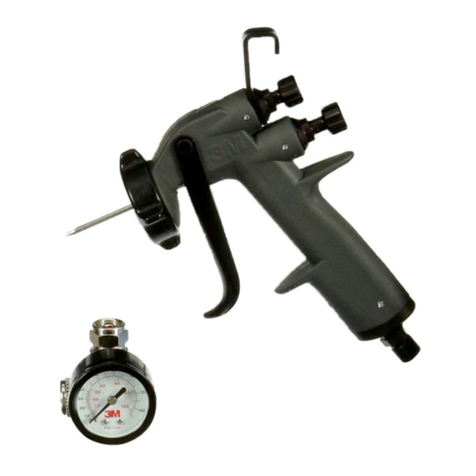
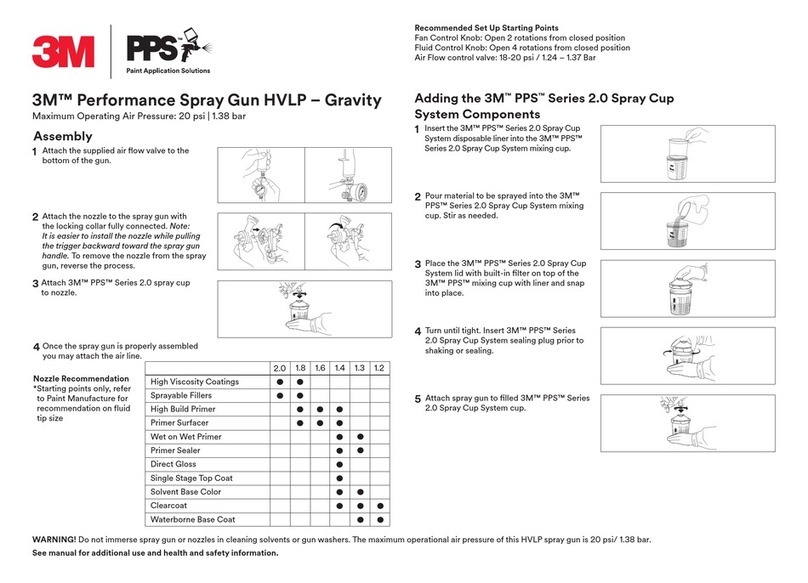
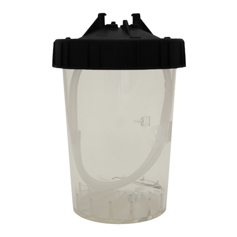
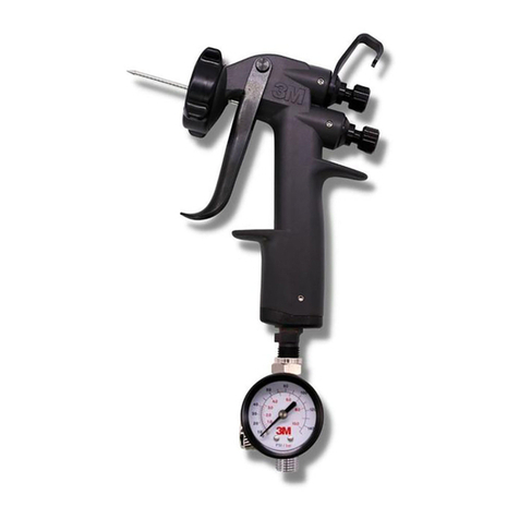
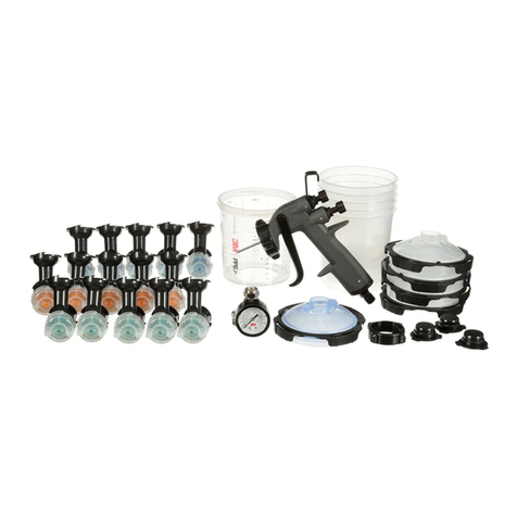
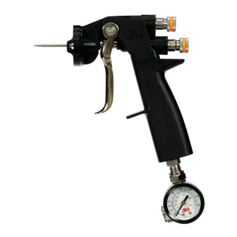
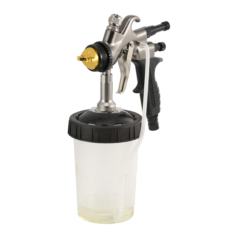
3M 16212 User manual

Paint Preparation System
Spray Guns
INTENDED USE: 3M–Graco spray gun systems are intended for use only by
trained and professional tradesmen, and used solely for the purpose of
spray application of liquid coating materials. They must be used only in
areas which are compatible with the material being sprayed, in strict
compliance with applicable local and national regulations.
HVLP, Compliant, and Airspray
100 psi (0.7 MPa, 7 bar) Maximum Working Air Pressure
29 psi (200 kPa, 2.0 bar) Maximum Compliant Inbound Air Pressure
(HVLP and Compliant)
U.S. Patent Pending
Table of Contents
Symbols 2. . . . . . . . . . . . . . . . . . . . . . . . . . . . . . .
Warnings 2. . . . . . . . . . . . . . . . . . . . . . . . . . . . . . .
Selection Charts 4. . . . . . . . . . . . . . . . . . . . . . . .
Typical Installation 5. . . . . . . . . . . . . . . . . . . . . . .
Setup 6. . . . . . . . . . . . . . . . . . . . . . . . . . . . . . . . . .
Operation 11. . . . . . . . . . . . . . . . . . . . . . . . . . . . .
Daily Gun Care, Flushing, and Cleaning 13. . .
Troubleshooting 16. . . . . . . . . . . . . . . . . . . . . . . .
Service 18. . . . . . . . . . . . . . . . . . . . . . . . . . . . . . .
Parts 24. . . . . . . . . . . . . . . . . . . . . . . . . . . . . . . . .
Accessories 27. . . . . . . . . . . . . . . . . . . . . . . . . . .
Dimensions 27. . . . . . . . . . . . . . . . . . . . . . . . . . . .
Technical Data 27. . . . . . . . . . . . . . . . . . . . . . . . .
Warranty 28. . . . . . . . . . . . . . . . . . . . . . . . . . . . . .
Contact Information 28. . . . . . . . . . . . . . . . . . . . .
Manufactured by
Instructions – Parts List
II 2 G
Important Safety Instructions
Read all warnings and instructions in this manual.
Save these instructions.

2
Symbols
Warning Symbol
WARNING
This symbol alerts you to the possibility of serious
injury or death if you do not follow the instructions.
Caution Symbol
CAUTION
This symbol alerts you to the possibility of damage to
or destruction of equipment if you do not follow the
instructions.
WARNING
INSTRUCTIONS
EQUIPMENT MISUSE HAZARD
Misuse can cause death or serious injury.
Do not exceed the maximum working pressure or temperature rating of the lowest rated system
component. See Technical Data in all equipment manuals.
Use fluids and solvents that are compatible with equipment wetted parts. See Technical Data in all
equipment manuals. Read fluid and solvent manufacturer’s warnings.
Check equipment daily. Repair or replace worn or damaged parts immediately.
Do not alter or modify equipment.
Use equipment only for its intended purpose. See intended use statement on front cover.
Route hoses and cables away from traffic areas, sharp edges, moving parts, and hot surfaces.
Do not use hoses to pull equipment.
Comply with all applicable safety regulations.
This equipment is to be used only by professional tradesmen who are familiar with its possible
hazards.
Read all instruction manuals, tags, and labels before operating the equipment.
Use the equipment only for its intended purpose. See intended use statement on front cover.

3
WARNING
PRESSURIZED EQUIPMENT HAZARD
Fluid from the gun/dispense valve, leaks, or ruptured components can splash in the eyes or on skin
and cause serious injury.
Follow the Pressure Relief Procedure on page 11 whenever you are instructed to relieve pres-
sure.
Do not stop or deflect fluid leaks with your hand, body, glove, or rag.
Do not point the spray gun at anyone or at any part of the body.
Tighten all fluid connections before operating the equipment.
Check hoses, tubes, and couplings daily. Replace worn or damaged parts immediately.
FIRE AND EXPLOSION HAZARD
Flammable fumes, such as solvent and paint fumes, in work area can ignite or explode. To help pre-
vent fire and explosion:
Use equipment only in well ventilated area.
Eliminate all ignition sources; such as pilot lights, cigarettes, portable electric lamps, and plastic
drop cloths (potential static arc).
Keep work area free of debris, including solvent, rags, and gasoline.
Do not plug or unplug power cords or turn lights on or off when flammable fumes are present.
Ground equipment and conductive objects in work area. See Grounding instructions on page 11.
If there is static sparking or you feel a shock, stop operation immediately. Do not use equipment
until you identify and correct the problem.
TOXIC FLUID OR FUMES HAZARD
Toxic fluids or fumes can cause serious injury or death if splashed in the eyes or on skin, inhaled, or
swallowed.
Read MSDS’s to know the specific hazards of the fluids you are using.
Store hazardous fluid in approved containers, and dispose of it according to applicable guidelines.
Gloves must be worn for spraying or cleaning equipment.
NOISE HAZARD
You must wear appropriate protective equipment when operating, servicing, or when in the operating
area of the equipment to help protect you from serious injury, including hearing loss.

4
Selection Charts
Spray Gun Assemblies
HVLP Guns – for high efficiency with low pressure
Gun and
PPS Cup
Assy.
Orifice Size Pattern
Length
Air Cap
Marking
Housing
Color
Part No.
in. (mm) in. (mm)
16212 .051 (1.3) 13 (330) H Purple
16213 .055 (1.4) 13 (330) H Purple
16214 .059 (1.5) 13 (330) H Purple
16215 .070 (1.8) 13 (330) H Purple
Airspray Guns
Gun and
PPS Cup
Assy.
Orifice Size Pattern
Length
Air Cap
Marking
Housing
Color
Part No.
in. (mm) in. (mm)
16204 .051 (1.3) 9 (228) A Black
16205 .055 (1.4) 9 (228) A Black
16206 .059 (1.5) 9 (228) A Black
16207 .070 (1.8) 9 (228) A Black
Compliant Guns
Gun and
PPS Cup
Assy.
Orifice Size Pattern
Length
Air Cap
Marking
Housing
Color
Part No.
in. (mm) in. (mm)
16208 .051 (1.3) 11 (279) C Gold
16209 .055 (1.4) 11 (279) C Gold
16210 .059 (1.5) 11 (279) C Gold
16211 .070 (1.8) 11 (279) C Gold
Measured with gun nozzle 8 in. (203 mm) from target surface

5
Selection Charts
Selecting the Proper Nozzle Size
Follow your material suppliers recommendations for
proper nozzle size. In general, use the smaller nozzle
sizes for low flow rates or light viscosity materials and
larger nozzle sizes for higher flows and higher viscosity
materials.
Typical Installation
KEY
A Gun
See page 25 for gun part numbers.
B 3M PPS Cup System
C Needle Valve Inlet; 1/4 npsm
D Air Hose
Recommend 5/16” (7.9 mm) ID hose
Optional 3/8” (9.5 mm) ID hose
E Air Shut-off Valve
F Air Regulator
G Air Filter
H Air Supply Line
A
C
D
EFGH
07600A
B
The spray guns were designed to produce the highest
quality finish with today’s automotive paint systems.
The HVLP and Compliant guns typically utilize 29 psi
(200 kPa, 2.0 bar) inbound air pressure to produce
high quality paint finishes and comply with environ-
mental regulations.
The air regulator must have a minimum air flow
capacity of 30 scfm at 100 psi (0.7 MPa, 7 bar) air
pressure.
Ventilate the Spray Booth
WARNING
To prevent hazardous concentrations of
toxic and/or flammable vapors, spray
only in a properly ventilated spray booth.
Do not operate the spray gun unless
ventilation fans are operating.
Check and follow all of the National,
State and Local codes regarding air ex-
haust velocity requirements.
Check and follow all local safety and fire codes.

6
Setup
Flushing the Spray Gun
NOTE: Flush the spray gun before putting any paint
through the gun.
To flush the gun, squeeze water or solvent into the gun
adapter while triggering the gun.
Make sure to use a solvent that is compatible with
paint to be sprayed.
Fig. 1 TI3610C
Connecting the Air Line
You must install an air pressure regulator (F) on the
gun air line to control air pressure to the gun. See
Fig. 3.
If your regulated air source does not have a filter,
install an air filter (G) on the air line to ensure a dry,
clean air supply to the gun. Dirt and moisture can
ruin the appearance of your finished workpiece.
See Fig. 3.
Use a 5/16 inch (7.9 mm) I.D. air hose to minimize
excessive pressure drop in the hose.
1. Connect the air hose (D) to the 1/4 npsm air inlet
(C).
D
C
Fig. 2
7033A
2. Connect the other end of the air hose (D) to a
regulated air supply line (H).
NOTE: Fig. 3 shows the filter (G) air regulator (F),
and air shut-off valve (E) on the air supply line.
01990
D
FG
Fig. 3
H
E

7
Setup
Installing 3MtPaint Preparation System (PPS)
Paint cup
Locking collar
Mix Ratio Film
(optional)
Paint cup lid
Paint cup liner
200 Micron Strainer
Sealing Cap
NOTE: 3MMix Ratio Film is optional.
1. Weigh paint in the cup with liner according to paint
manufacturers instructions before mixing product.
Fig. 4
2. Mix product as needed.
3. Take the lid (with built in strainer) and snap onto
the top of PPS cup.
4. Position locking collar onto the PPS cup and turn
until tight.
5. With spray gun inverted, lower onto PPS cup and
lock gun adapter, turning clockwise, to lid.
Fig. 5

8
Setup
6. Make sure that the lid fingers are fully engaged
above adapter edge.
Fig. 6
7. With air line connected, invert gun and pull trigger
(fully open NOT partially) to bleed air from the liner
NOTE: Air only needs to be bled if spraying in the
inverted position.
Fig. 7
8. With the air removed from the liner, the gun may
be sprayed upside down or in any direction to
reach difficult areas.
Fig. 8

9
Setup
WARNING
PRESSURIZED EQUIPMENT HAZARD
To reduce the risk of a serious injury, follow the
Pressure Relief Procedure on page 11 whenever
you are instructed to relieve pressure.
Positioning the Air Cap
Rotate the air cap as needed to achieve the desired
spray pattern direction. To create a round pattern, turn
the pattern air off by turning the pattern adjustment
knob (25) fully clockwise. Refer to Fig. 11.
Vertical Pattern
Horizontal Pattern
Fig. 9 02020
Adjusting the Spray Pattern
Follow these steps to establish the correct fluid flow
and air flow:
1. Turn the fluid adjustment knob (21) counterclock-
wise until no restriction of the trigger movement is
felt, then turn out another half turn. When the knob
is turned far enough, the trigger should be able to
touch the gun handle when the gun is triggered.
WARNING
PRESSURIZED EQUIPMENT HAZARD
To avoid injury, never open the fluid adjustment
knob (21) beyond the one half turn indicated in
Adjusting the Spray Pattern. If the red band on
the knob stem (21) is visible, the knob is not ad-
justed correctly and could result in serious injury.
Repeat steps in Adjusting the Spray Pattern.
Fig. 10
21
open
TI3615a
2. Turn the pattern adjustment valve (25) fully coun-
terclockwise to achieve the widest fan pattern.
Fig. 11
25
Open
(wider
pattern)
Close
(narrower
pattern)
TI3615A

10
Setup
3. Adjust the air supply regulator (F) to about 100 psi.
Fig. 12
F
01997
4. Trigger the gun and adjust the gun inlet pressure,
turning the needle valve at the gun air inlet:
HVLP, Compliant 29 psi
Airspray 50psi
5. Spray a test pattern to evaluate fluid flow and
atomization.
6. To reach the desired pattern width, fluid flow rate,
and finish, make the following adjustments:
. For a narrower pattern (25), turn the pattern
adjustment valve clockwise.
. To reduce the fluid flow, turn the fluid adjust-
ment valve (21) clockwise to limit the trigger
travel or replace the nozzle with a smaller
orifice.
. To improve atomization, reduce the fluid flow
rate. Increasing the air pressure can improve
atomization but may result in poor Transfer
Efficiency (TE) or non–compliant operation.
WARNING
PRESSURIZED EQUIPMENT HAZARD
To avoid injury, never open the fluid adjustment
knob (21) beyond the one half turn indicated in
Adjusting the Spray Pattern, page 9. If the red
band on the knob stem (21) is visible, the knob is
not adjusted correctly and could result in serious
injury. Repeat steps in Adjusting the Spray
Pattern, page 9.
7. For HVLP only, to measure the air cap atomizing
pressures, use the accessory aircap verification
kit.
NOTES:
If the fluid adjustment knob is turned in clockwise
all the way the gun will emit only air.
For maximum transfer efficiency, always use the
lowest air setting needed to achieve the desired
finish.
If available, use the fluid manufacturer’s recom-
mendations for this gun model to set the air line
pressure.
For Compliant guns, to maintain compliant opera-
tion (TE equal to HVLP) the gun inlet pressure must
not exceed 29 psi.
For HVLP guns, at 29 psi (200 kPa, 2.0 bar) gun
inlet air pressure, the pressure at the aircap will be
10 psi (70 kPa, 0.7 bar).
For HVLP guns, local laws may limit the maximum
automatic air pressure to 10 psi (70 kPa, 0.7 bar) at
the air cap for HVLP compliance. The accessory Air
Cap Verification Kit 16231 is available to measure
the atomizing pressure at the air cap.

11
Operation
WARNING
PRESSURIZED EQUIPMENT HAZARD
The system pressure must be manually relieved to
prevent the system from starting or spraying acci-
dentally. To reduce the risk of an injury from acci-
dental spray from the gun, splashing fluid, or
moving parts, follow the Pressure Relief Proce-
dure whenever you:
are instructed to relieve the pressure,
stop spraying,
check or service any of the system equipment,
or install or clean the spray nozzle.
Pressure Relief Procedure
1. Turn off the air supply to the gun.
2. Disconnect air line from the gun.
3. Invert gun and pull trigger (fully open, not partially)
to return mix to gun cap.
Fig. 13
Grounding
All conductive equipment is subject to static electricity
buildup (read Warnings, page 3). To reduce the risk
of static sparks, the system must be grounded using
appropriate connectors and conductors. Use only
electrically conductive hoses.

12
Operation
Applying the Fluid
1. To achieve the best results when applying fluid,
keep the gun perpendicular to the surface and
maintain a consistent distance of approximately 6
to 8 inches (150 to 200 mm) from the object being
sprayed. See Fig. 14.
2. To obtain an even finish, use smooth, even strokes
across the surface to be sprayed with 50% over-
lap. The PPS gun cup is a sealed system and can
be sprayed in any direction without spills on verti-
cal or horizontal surfaces.
3. Paint using parallel strokes. This spray gun applies
all coatings evenly without cross coating.
WRONG RIGHT
Fig. 14 0793

13
Daily Gun Care, Flushing, and Cleaning
WARNING
PRESSURIZED EQUIPMENT HAZARD
To reduce the risk of a serious injury, follow the
Pressure Relief Procedure on page 11 whenever
you are instructed to relieve pressure.
CAUTION
Solvent left in gun air passages could result in a poor quality paint finish. Do not use any cleaning method which
may allow solvent into the gun air passages. Do not expose needle valve and gauge (30) to solvents or
gauge may be damaged.
02055
Do not immerse the gun in solvent.
Do not wipe the gun with a cloth soaked in
solvent; ring out the excess.
Do not point the gun up while cleaning it.
Do not use metal tools to clean the air cap
holes as this may scratch them; scratches can
distort the spray pattern.
0202707042A
07041A
General System Maintenance Check
Relieve the pressure.
Clean the fluid and air line filters daily.
Check for any fluid leakage from the gun and fluid
hoses.
Flush the gun before changing colors and when-
ever you are done operating the gun.

14
Daily Gun Care and Cleaning
Removing the paint supply
WARNING
PRESSURIZED EQUIPMENT HAZARD
To reduce the risk of a serious injury, follow the
Pressure Relief Procedure on page 11 whenever
you are instructed to relieve pressure.
1. Relieve the pressure, page 11.
2. Remove PPS cup by inverting the gun. Turn the
gun counterclockwise unlocking the gun adapter
from the paint cup.
3. Flush the spray gun, page 6.
4. To retain unused paint, seal the lid with the PPS
sealing cap, label, and temporarily store mixed
material in PPS cup.
5. When the PPS cup is empty the collapsed liner
and lid may be disposed. Consult all local, state,
and federal regulations or authorities for proper
disposal.
Cleaning the gun
1. Remove the air cap retaining ring (15) and air cap
(14).
2. Trigger the gun while you remove the fluid nozzle
(12) from the gun with the gun tool (28).
12
28
Fig. 15
TI3616C
14, 15
CAUTION
Trigger the gun whenever you tighten or remove the
nozzle. This keeps the needle seat away from the
nozzle seating surface and prevents the seat from
being damaged.
3. Clean the air cap retaining ring, air cap, and fluid
nozzle with solvent.
4. Dip the end of a soft-bristle brush into a compatible
solvent. Do not continuously soak the brush’s
bristles with solvent and do not use a wire brush.
Fig. 16 02007

15
Daily Gun Care and Cleaning
5. With the gun pointed down, clean the front of the
gun, using the soft-bristle brush and solvent.
Fig. 17
TI13624a
6. Scrub the air cap retaining ring, air cap, and fluid
nozzle with the soft-bristle brush. To clean out air
cap holes, use the small brush provided. Clean the
air cap and fluid nozzle daily, minimum. Some
applications require more frequent cleaning. Do
not soak the air cap retaining ring in solvent for
prolonged periods of time.
Fig. 18 02011
7. To avoid galling of the fluid nozzle in the spray
housing (2a) apply a thin film of lubricant to the
back surface of the nozzle taper where it seats
and also to the nozzle threads. Trigger the gun
while you install the fluid nozzle (12) with the gun
tool (28). Tighten the nozzle securely to 40 in-lb
(4.5 Nm) to obtain a good seal. Do not over
torque.
8. Install the air cap retaining ring (15) and air
cap (14).
Fig. 19
Torque to 40 in-lb (4.5 Nm)
7
712
28
TI3616C
14, 15
9. Dampen a soft cloth with solvent and wring-out the
excess. Point the gun down and wipe off the
outside of the gun.
Fig. 20
TI3617a

16
Troubleshooting
WARNING
PRESSURIZED EQUIPMENT HAZARD
To reduce the risk of a serious injury, follow the
Pressure Relief Procedure on page 11 whenever
you are instructed to relieve pressure.
Correct fan pattern Follow all Setup procedures, starting on page 6. Hang some 3M masking
paper. Hold spray gun with Air Cap perpendicular and 8 in. from masking
paper. Spray for two seconds and check what you get for fan pattern
outline on the paper. See troubleshooting chart for how to adjust/service
spray gun to correct Fan Pattern defects.
PROBLEM CAUSE AND SOLUTION
Fluttering or spitting spray Loose or damaged fluid tip/seat (Tighten or replace).
Material level too low in cup (Refill cup)
Gun cup tilted too far over or upside down while spraying (Purge Air out of
PPS cup).
PPS 200–micron strainer too fine for mix (Use PPS 300 micron strainer or
thin/reduce mix).
Partial obstruction in fluid passage (Flush with solvent).
Dry or loose fluid needle packing nut (Lubricate or tighten).
Pattern is curved. Air Cap or Fluid Tip Defective. Determine if defect is in the Air Cap or Fluid
Tip. Rotate Air Cap one–half turn and spray another test pattern. If defect
is inverted/reverse of previous fan pattern, then defect is in the Air Cap.
Clean air Cap.
If defect is not inverted/reverse of previous Fan Pattern, defect is in the
Fluid Tip. Check Fluid Tip for damage or partial blockage with dried materi-
al. Check Fluid Needle Tip for damage. Replace as necessary.
Pattern is off–set or heavy on one
end.
One or more Air Horn Holes Plugged (Clean Air Cap)
Fluid Needle Tip Damaged (Replace Fluid Needle Tip)
Fluid Nozzle Damaged or partially blocked.(Clean and or replace Fluid
Nozzle)
Pattern is heavy in the center.Air Pressure too low (Increase Air Pressure).
Fan Pattern set too narrow (Open Fan Pattern).
Material is too thick (Reduce/Thin the Mix).
Pattern is split. Air Pressure too high (Reduce Air Pressure).
Fan Pattern set wide open (Close down Fan Pattern).

17
PROBLEM SOLUTION
Starving Fan Pattern.
Fan pattern begins to narrow down.
PPS liner bottomed out on top of strainer or collapsed around strainer, block-
ing flow (Disconnect air, with PPS cup below gun, pull trigger to re–open liner,
re–connect air and spray mix without purging air from liner).
PPS 200–micron strainer too fine for mix (Use PPS 300 micron strainer or thin/
reduce mix).
Air supply pressure drops due to air supply defects such as other air tools be-
ing used draws down system pressure & CFM flow.
Will not spray. Not enough flow/air pressure at gun (Check air supply source and hose).
Fluid needle not open enough (Open fluid needle more).
Mix is too thick for fluid tip size (Change to larger size).
Fluid leaking/dripping from PPS
cup.
PPS cup lid loose (Tighten PPS Locking Collar).
Crack in PPS Lid or Liner (Replace).
PPS lid spout not fully engaged with PPS Adapter.
Fluid leaking/dripping from gun. Check for missing or damaged O–ring (34) at base of Fluid Nozzle on the
Fluid/Adapter Housing
Fluid needle packing nut too tight or binding (Loosen nut or lubricate
needle shaft).
Needle tip damaged (Replace).
Fluid Nozzle nicked or damaged (Replace).
Mix residue dried in gun (Clean & Lube gun).
Excessive overspray. Too much air pressure (Reduce air pressure).
Gun too far from work surface (Move in and keep the fan pattern perpen-
dicular to the surface to be sprayed).

18
Service
Fig. 21
Lightly lubricate
Lightly lubricate threads
Torque to 125–135 in-lb (14–15 Nm)
Torque to 20–30 in-lb (2.3–3.4 Nm)
U-cup lips face air valve assembly (26)
U-cup lips face away from nut (19/25a)
Torque to 40 in-lb (4.5 Nm)
U–cup lips face towards the front of the gun (15b
)
*Parts included in Rebuild Kit 16230
Item 2 includes 2a–2b
Item 13 includes item 13a
Item 25 includes 25a–25d
29 28
1
2
3
4
5
6
7
8
TI3619F
1
4
2a2b*
5*
8
9
10
11
17
12
13
14
13a
15
26*
16*
22*
20*
23*
19
24
25c
21
25a
25b*
25d
18
30 30a
34*
15b*
1
1
1
1
2
3
3
3
3
5
4
6
6
7
A
35*
HVLP
(two grooves)
Airspray
(no groove)
HVLP
(smaller ID)
Airspray
and Compliant
2
2
8
Compliant
(one groove)

19
Service
Replacing the air and fluid packings
with gun rebuild kit 16230
Tools Needed:
Wrench 5/16 in. (8 mm)
Wrench 3/4 in. (19 mm)
Gun Tool (28) supplied with gun
Packing Installation Tool (29)
supplied with gun
Mechanics O–ring pick
Needle nose plier
Gun Lube Part No. 16232
WARNING
PRESSURIZED EQUIPMENT HAZARD
To reduce the risk of a serious injury, follow the
Pressure Relief Procedure on page 11 whenever
you are instructed to relieve pressure.
NOTE:
Gun Repair Kit 16230 comes complete with all air
and fluid seals required to rebuild the spray gun.
Clean parts with a solvent that is compatible with
the parts and the fluid being sprayed.
Lightly lubricate the parts indicated in Fig. 21 with
lubricant 16232. This item is not included with gun.
Disassembling the gun
1. Relieve the pressure.
2. Flush the spray gun, page 6.
3. Remove the air cap retaining ring (15) and air cap
(14). Remove and replace the seal (15B). The
U–cup lips must face towards the air cap. See Fig.
22.
Fig. 22
12
15B
28
TI3616C
14, 15
4. Trigger the gun while you remove the fluid nozzle
(12) with the gun tool (28).
CAUTION
Trigger the gun whenever you tighten or remove the
nozzle. This keeps the needle seat away from the
nozzle seating surface and prevents the seat from
being scratched.
5. Remove the fluid adjustment knob (21) and fluid
spring (23). See Fig. 21, page 18.
6. Pull the fluid needle (13) out the back of the gun.
7. Remove the screw (11), pin (17), wave washer
(18), and trigger (10).
8. Remove the hex nut (9) with the gun tool (28).
9. Remove the spray housing (2a) and adapter (4).

20
Service
Replacing the spray housing o–rings
and packings
Fig. 23
1
4
2a
2b*
5*
8
9
11
12
14
15 18
34*
15b*
17
10
1. With the spray housing (2a) removed from the
adapter (4), use a mechanical pick to remove the
o-ring (2b) from the housing (2a).
2. Remove o–ring (34) from the adapter (4). See Fig.
23.
NOTE: O–ring (2b) is slightly larger than o–ring
(34).
3. Install a new o–ring (34) into the adapter (4). Install
a new o–ring (2b) into the housing (2a).
NOTE: To ease o-ring installation, place the adapter
(4) into the spray housing (2a) to plug the end. Install
one end of the o-ring into the groove in the housing,
then press the rest of the o-ring into place.
4. Unscrew the packing screw (8) from the adapter
(4) with the gun tool (28).
5. Using a mechanical pick, push the three fluid
packings (5) out of the adapter (4). Be careful not
to damage the adapter. Discard the old fluid pack-
ings.
6. Place the new fluid packings (5) and packing
screw (8) onto the needle (13). See Fig. 24 for the
orientation of the parts.
Fig. 24
5*
8
7. Insert the fluid needle (13) into the back of the
adapter (4) to install the fluid packings (5).
8. Tighten the packing screw (8) just enough to hold
the packings (5) in the adapter (4). The needle
(13) must move freely. Remove the needle.
This manual suits for next models
11
Table of contents
Other 3M Paint Sprayer manuals

3M
3M Series 05 User manual

3M
3M PPS Series 2.0 User manual

3M
3M PPS Series 2.0 User manual

3M
3M Scotchkote HSS-450 User manual

3M
3M Accuspray User manual

3M
3M Accuspray HGP Spray Gun User manual

3M
3M Performance Spray Gun User manual

3M
3M Accuspray 26580 User manual

3M
3M Series 52 User manual

3M
3M PPS 16121 User manual