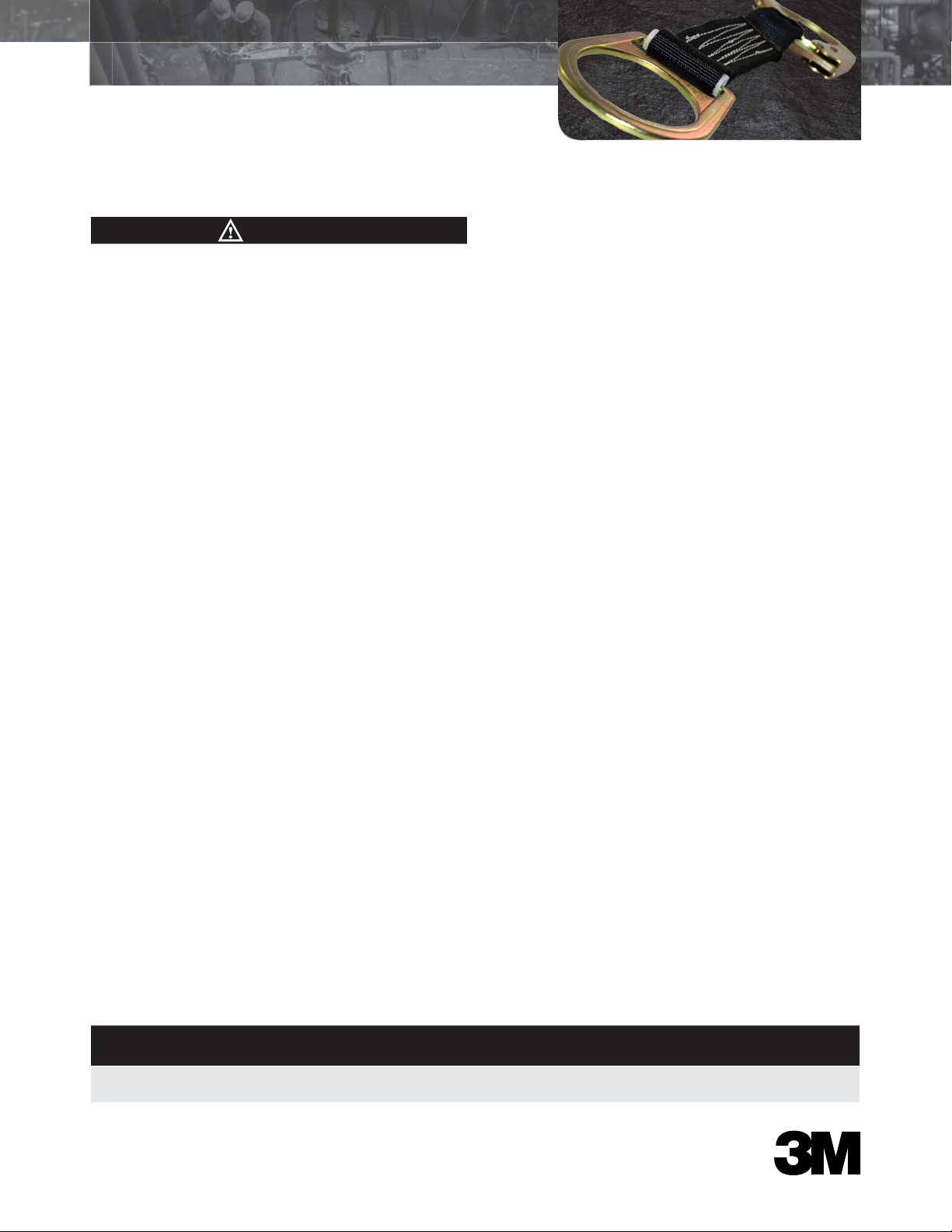
manuals.online logo
Brands
  1. Home
  2. •
  3. Brands
  4. •
  5. 3M
  6. •
  7. Safety Equipment
  8. •
  9. 3M 5551 User manual

3M 5551 User manual

Part Number
3M ID Material Length Gate Opening D-Ring
Connector Weight Compliance
Standards
5551
70071532561
Polyester;
Steel
18 in
(457 mm)
2.4 in
(60 mm)
2.4 in
(62 mm)
1.9 lb
(861 g) ANSI Z359.1-07
General Safety Information
These User Instructions are not to be removed except by the
user of this equipment. User Instructions must always be
available to the user.
Compliant fall protection and emergency rescue systems
help prevent serious injury during fall arrest. Users must
read and understand the User Instructions provided with the
product and be properly trained by their employer prior to
use per OSHA 29 CFR 1910.66 and 1926.503 or applicable
local standards. Misuse or failure to follow warnings and
instructions may result in serious personal injury or
death. For proper use, see supervisor, User Instructions, or
call Technical Service at 800-243-4630.
Purpose
3M 5551 Anchorage Connectors are designed to be used
as part of a personal fall arrest system, to help limit the fall
arrest forces in the event of a fall.
Use Instructions
1. Failure to follow all instructions and limitations on the
use of 5551 Anchorage Connectors may result in serious
personal injury or death.
2. Before using a personal fall arrest system, employees
must be trained in accordance with the requirements of
OSHA 29 CFR 1910.66 in the safe use of the system and
its components.
3. Personal fall arrest systems, including 5551 Anchorage
Connectors, must be inspected prior to each use for
wear, damage, and other deterioration and defective
components must be immediately removed from service,
in accordance with the requirements of OSHA 29 CFR
1910.66 and 1926.502.
4. The complete fall protection system must be planned
(including all components, calculating fall clearance, and
swing fall) before using.
5. Users must have a rescue plan, and the means at
hand to implement it, that provides the prompt rescue
of employees in the event of a fall or assures that
employees are able to rescue themselves.
6. Store 5551 Anchorage Connectors in a cool, dry, clean
environment, out of direct sunlight, when not in use.
7. After a fall occurs, the 5551 Anchorage Connector must
immediately be removed from service and destroyed.
Use Limitations
1. 5551 Anchorage Connectors are designed for single user
only.
2. 5551 Anchorage Connectors must only be used on
structures capable of supporting static loads applied in
all directions permitted by the fall arrest system of at
least: 3,600 lb (16.0 kN) with certification of a qualified
person, or 5,000 lb (22.2 kN) without certification.
3. 5551 Anchorage Connectors are designed to be used in
temperatures ranging from -40ºF to +130ºF (-40°C to
+54°C).
4. Do not expose 5551 Anchorage Connectors to chemicals
or harsh solutions which may have a harmful effect.
Contact 3M Technical Service with any questions.
5. Caution must be taken when using 5551 Anchorage
Connectors near moving machinery, electrical hazards,
sharp edges, or abrasive surfaces, as contact may cause
equipment failure, personal injury, or death.
6. Minors, pregnant women and anyone with a history
of either back or neck problems should not use this
equipment.
7. Do not use or install equipment without proper training
from a “competent person” as defined by OSHA 29 CFR
1926.32(f).
8. Only 3M, or persons or entities authorized in writing by
3M, shall make repairs or alterations to the equipment.
Compatibility Limitations
5551 Anchorage Connectors must only be coupled to
compatible connectors. OSHA 29 CFR 1926.502 prohibits
snaphooks from being engaged to certain objects unless two
requirements are met: snaphook must be a locking type and must
be “designed for” making such a connection. “Designed for”
means that the manufacturer of the snaphook specifically
designed the snaphook to be used to connect to the
equipment in question. The following connections must be
avoided, as they are conditions that can result in rollout*
when a nonlocking snaphook is used:
• Direct connection of a snaphook to horizontal lifeline.
• Two (or more) snaphooks connected to one D-ring.
• Two snaphooks connected to each other.
• A snaphook connected back on its integral lanyard.
• A snaphook connected to a webbing loop or webbing
lanyard.
• Improper dimensions of the D-ring, rebar, or other
connection point in relation to the snaphook dimensions
that would allow the snaphook keeper to be depressed by
a turning motion of the snaphook.
*Rollout: A process by which a snaphook or carabiner
unintentionally disengages from another connector or object
to which it is coupled. (ANSI Z359.0-2007)
Performance
3M 5551 Anchorage Connectors have a minimum tensile
breaking strength of 5,000 lbs (22.2 kN) when statically
tested in accordance with the requirements of the ANSI
Z359.1-2007 standard.
WARNING
5551 Anchorage Connector
User Instructions
5551 Anchorage Connector
User Instructions
Installation
5551 Anchorage Connectors must be installed on structures
capable of meeting the anchorage strength requirements of
OSHA 29 CFR 1910.66 and 1926.502.
Attach the rebar hook end of the 5551 Anchorage Connector
to the anchorage. The D-ring of the 5551 becomes the
attachment point for the fall arrest system.
Inspection
All 5551 Anchorage Connectors must be inspected prior to
each use, and annually by an OSHA defined “competent
person” other than the user.
If inspection reveals any defect, inadequate maintenance,
or unsafe condition, remove from service and destroy.
Any equipment that has been subjected to the forces
of arresting a fall must immediately be removed from
service and destroyed.
Inspecting webbing for tears, cuts, fraying, abrasion,
discoloration, burns, holes, mold, pulled or broken stitches, or
other signs of wear and damage.
All 5551 Anchorage Connectors must be free of corrosion,
chemical attack, alteration, excessive heating or wear.
All markings must be legible and attached to the product.
Note: Only manufacturer, or entities authorized in
writing by the manufacturer, may make repairs to the
product.
Cleaning and Maintenance
5551 Anchorage Connectors can be wiped down with a
mild detergent and clean water solution, and rinsed with a
dampened clean cloth to remove detergent. The hardware can
also be wiped down to remove grease, or dirt with a clean dry
cloth.
Product Label
Please recycle. Printed in USA.
© 3M 2012
3M is a trademark of 3M Company,
used under license in Canada.
All rights reserved.
IM-0058 (04-2012) 34-8710-0339-7
3M Occupational Health &
Environmental Safety Division
3M Center Building 235-2W-70
Saint Paul, MN 55144-1000
USA
Technical Assistance: 800-243-4630 in U.S.
and 800-267-4414 in Canada
www.3M.com/FallProtection
www.3M.com/PPESafety
Product Warranty, Limited Remedy, and Limitation of Liability
WARRANTY: THE FOLLOWING IS MADE IN LIEU OF ALL WARRANTIES OR CONDITIONS, EXPRESS OR
IMPLIED, INCLUDING THE IMPLIED WARRANTIES OR CONDITIONS OF MERCHANTABILITY OR FITNESS FOR
A PARTICULAR PURPOSE. Equipment offered by 3M is warranted against factory defects in workmanship and materials for
a period of one year from date of installation or first use by the original owner.
LIMITED REMEDY: Upon notice in writing, 3M will repair or replace all defective items at 3M’s sole discretion. 3M reserves
the right to require that the defective item be returned to its plant for inspection before determining the appropriate course of
action. Warranty does not cover equipment damage resulting from wear, abuse, damage in transit, failure to maintain the product
or other damage beyond the control of 3M. 3M shall be the sole judge of product condition and warranty options. This warranty
applies only to original purchaser and is the only warranty applicable to this product. Please contact 3M technical service
department at 800-243-4630 for assistance.
LIMITATION OF LIABILITY: IN NO EVENT WILL 3M BE LIABLE FOR ANY INDIRECT, INCIDENTAL, SPECIAL
OR CONSEQUENTIAL DAMAGES INCLUDING, BUT NOT LIMITED TO LOSS OF PROFITS, IN ANY WAY RELATED
TO THE PRODUCTS REGARDLESS OF THE LEGAL THEORY ASSERTED.
ISO 9001
FM 573368

This manual suits for next models

1

Other 3M Safety Equipment manuals

3M DEUS 7300 User manual

3M

3M DEUS 7300 User manual

3M DBI SALA Sealed-Blok 3400803 User manual

3M

3M DBI SALA Sealed-Blok 3400803 User manual

3M DBI-SALA LAD-SAF Series User manual

3M

3M DBI-SALA LAD-SAF Series User manual

3M DBI-SALA Nano-Lok XL User manual

3M

3M DBI-SALA Nano-Lok XL User manual

3M DBI SALA LAD-SAF X3 User manual

3M

3M DBI SALA LAD-SAF X3 User manual

3M DBI SALA NANO-LOK EDGE Operator's manual

3M

3M DBI SALA NANO-LOK EDGE Operator's manual

3M DBI SALA Nano-Lok User manual

3M

3M DBI SALA Nano-Lok User manual

3M Peltor WS Tactical Sport User manual

3M

3M Peltor WS Tactical Sport User manual

3M DBI-SALA Nano-Lok edge 3500266 User manual

3M

3M DBI-SALA Nano-Lok edge 3500266 User manual

3M W-3060 User manual

3M

3M W-3060 User manual

3M NANO-LOK 3500276 User manual

3M

3M NANO-LOK 3500276 User manual

3M DBI SALA 3101207 User manual

3M

3M DBI SALA 3101207 User manual

3M Peltor SportTac MT16H210F-478 User manual

3M

3M Peltor SportTac MT16H210F-478 User manual

3M Nanolock 3101214 User manual

3M

3M Nanolock 3101214 User manual

3M Peltor X Series User manual

3M

3M Peltor X Series User manual

3M DBI SALA 5908549 Operator's manual

3M

3M DBI SALA 5908549 Operator's manual

3M Protecta Trolmatic Operator's manual

3M

3M Protecta Trolmatic Operator's manual

3M PELTOR WS LiteCom Plus Instruction Manual

3M

3M PELTOR WS LiteCom Plus Instruction Manual

3M Protecta 1161200 User manual

3M

3M Protecta 1161200 User manual

3M 5936792 User manual

3M

3M 5936792 User manual

3M AC40 Series Operator's manual

3M

3M AC40 Series Operator's manual

3M DBI-SALA Delta User manual

3M

3M DBI-SALA Delta User manual

3M Protecta Operator's manual

3M

3M Protecta Operator's manual

3M DBI SALA EXOFIT X300 User manual

3M

3M DBI SALA EXOFIT X300 User manual

Popular Safety Equipment manuals by other brands

Ferno XTRIC8 User instructions

Ferno

Ferno XTRIC8 User instructions

Dräger Oxyboks KT Instructions for use

Dräger

Dräger Oxyboks KT Instructions for use

Ganter Norm DIN 580 Operating	 instruction

Ganter Norm

Ganter Norm DIN 580 Operating instruction

Kentek 3+PRO KXL-C115C instructions

Kentek

Kentek 3+PRO KXL-C115C instructions

A.HABERKORN HERKULES INSTRUCTIONS FOR USE AND TEST MANUAL

A.HABERKORN

A.HABERKORN HERKULES INSTRUCTIONS FOR USE AND TEST MANUAL

Crossfire DG3 quick start guide

Crossfire

Crossfire DG3 quick start guide

Tractel stopfor B Operating and maintenance instructions

Tractel

Tractel stopfor B Operating and maintenance instructions

EUCHNER MGB-L1 AR Series operating instructions

EUCHNER

EUCHNER MGB-L1 AR Series operating instructions

Ferno 436 Series quick start guide

Ferno

Ferno 436 Series quick start guide

Petzl VIZIR TECHNICAL NOTICE

Petzl

Petzl VIZIR TECHNICAL NOTICE

Tractel LDR 06 Installation, operating and maintenance manual

Tractel

Tractel LDR 06 Installation, operating and maintenance manual

JSP FAR0804 INSTRUCTIONS ON USE, CARE AND INSPECTION

JSP

JSP FAR0804 INSTRUCTIONS ON USE, CARE AND INSPECTION

Skywalk DROP Pro Guide

Skywalk

Skywalk DROP Pro Guide

MSA AirXpress One Fire operating manual

MSA

MSA AirXpress One Fire operating manual

ABS ABS-Lock III-R installation manual

ABS

ABS ABS-Lock III-R installation manual

Power Hawk P-16X instruction manual

Power Hawk

Power Hawk P-16X instruction manual

Honeywell EBI XLS MASS NOTIFICATION SYSTEM Configuration, Preset Setup, Operation

Honeywell

Honeywell EBI XLS MASS NOTIFICATION SYSTEM Configuration, Preset Setup, Operation

AAT Holding KaDe KDH-EXIT1030-P installation manual

AAT Holding

AAT Holding KaDe KDH-EXIT1030-P installation manual

manuals.online logo
manuals.online logoBrands
  • About & Mission
  • Contact us
  • Privacy Policy
  • Terms and Conditions

Copyright 2025 Manuals.Online. All Rights Reserved.