3M 1BS-T Series User manual

READ FIRST
3MTM Filter Housing
1BS-T/1BS-TW Series
Operation Manual
■Read the Manual Thoroughly for Safe and Correct Operation.
■Keep the Manual Carefully at Hand for Quick Reference When Required.
CONTENTS
Introduction 1
For Your Safety 1,2
Attention to galling or seizure of
treaded portions 2
Specifications 3
Part names 4
Installation and piping 5
Flushing and cleaning 5
How to assemble a cartridge 6,7
Filtration process 8
How to remove a cartridge 8
Maintenance 9
Consumables 10
Product warranty 10

1
Introduction
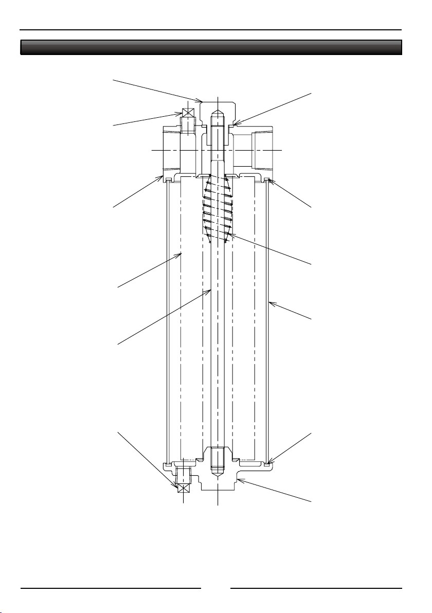
This instruction manual applies to 3MTM filter housing, 1BS-T / 1BS-TW series.
■Read this manual before you use the filter housing.
■Read this manual carefully to understand it well and use the filter housing properly.
■Store the manual with care after you read it and refer to it whenever necessary.
■If you misplace or lose the manual, inform it to us or our agent promptly.
■If you use the filter housing in the way different from the way described in this manual, we cannot guarantee security.
■Do not duplicate or reprint this manual without permission from 3M.
■In order that you use the housing filter safely, this manual contains pictorial indications below.
For your safety
■Use this filter housing below the design pressure. Otherwise, it may cause leakage or breakage.
■Never use gases with the filter housing. If it should be broken, there may cause damages to human bodies and
properties.
■If you open or close the valves in an abrupt manner, the filter housing may be damaged due to pulsations of the
line pressure. Besides if you apply a shock, excessive flow rate or back flow to the filter housing, it may cause
damages to the cartridge or housing. Never use the filter housing in such improper ways.
■Never use the housing filter for corrosive fluids. In addition check the fluid in advance to see if it is appropriate to
the filter housing of 1BS-T/1BS-TW.
■To prevent electrostatic accumulation of electricity, Use a ground wire.
■When you use the filter housing for high-temperature fluid, its surface will become hot. Pay enough attention
when you handle the housing.
■When you replace a cartridge with another, release the pressure in the filter housing. Especially when you use
high-temperature fluid, it may blow out.
■Deterioration or destruction of gaskets and others may cause the fluid used to blow out. Inspect them regularly
and replace them if deterioration or destruction is detected.
■For the maximum allowable working pressure, working temperature, flow-rate and others, observe the conditions
specified when the filter housing was selected.
Pictorial Indications
In order to prevent harms to the people who use the filter housing and damages to the properties by guiding the
proper usage, this manual employs pictorial indications below in relation to safety labeling and operational
information including cautions.
This Symbol Represents a WARNING to Ensure Safe and Correct Operation. Failure to observe this warning
could result in personal critical injuries or death.
This Symbol Represents a CAUTION to Ensure Safe and Correct Operation. Failure to observe this caution could
result in personal injuries or damages on the assets only.
Please follow the instructions indicated by this symbol.
Useful tips for operations.
CAUTION
CAUTION
Operation
WARNING
WARNING

2
■When you detect anything wrong with the filter housing body or gaskets and others (e.g. damages), stop using it
immediately.
Attention to galling or seizure of treaded portions
It is said that in general stainless steel is likely to have galling or seizure because its thermal conductivity is lower
than ordinary steel and the thread surface develops larger heat and expands more.
Galling or seizure can be reduced by taking appropriate actions but in fact existing technologies cannot eliminate
galling or seizure as well as contamination by foreign matters completely.
For the threaded portions of this device (center rod and cap nut, and center rod and cover), stainless steel is used.
Therefore, please use the device in an appropriate manner while paying attention to the items described below in
order to prevent galling or seizure.
■In order to prevent galling of stainless steel components, surface coating or appropriate lubricant should be used
to reduce friction and to improve thermal conductivity.
■Neither special disposition nor treatment is applied for the threaded portions of this device. Please use the
lubricant optimal to your working conditions.
■When you remove the cap nut, take the most care not to let the threaded portion contaminated by foreign matters.
When you install it, fasten it with the specified torque at maximum.
■In case you have not removed the cartridge for a long time, the threaded portions may be solidified. In that case,
check the threaded portions of the center rod, cap nut and cover if anything sticks to them after the components
are removed. If anything remains, take it away before reassembling the device.
■When you assemble the threaded portions, first turn them a few times manually to verify there is no galling. Then,
use the tools to fasten them.
■If leakage of the fluid used occurs to the sealing portions of the shell gasket or the nut gasket, fasten the cap nut
with the specified torque at maximum. Then, if leakage cannot be stopped, the gaskets may be deteriorated,
damaged or deformed. So, please replace them by new ones and fasten them again.
■If you forcibly fasten the threaded portions, it may cause galling. So, never fasten them with force.
Please understand we do not include galling or seizure of the threaded portions of this device in our
guarantee.
Operation

3
Specifications
Design pressure 0.98MPa
Materials
Head SCS14
Cover SCS14
Shell 316SS
Rod & Nut 316SS
Gasket PTFE
Major dimensions
Shell’s outer diameter 89.1mm
Height
1BS1-T/TW 341mm
1BS2-T/TW 589mm
Weight
1BS1-T/TW 2.8kg(max)
1BS2-T/TW 4.1kg(max)
Capacity
1BS1-T/TW 1.4L(max)
1BS2-T/TW 2.8L(max)
Port size
Inlet/Outlet nozzle
1BS1-T/TW 15A/20A/25A Rc
1BS2-T/TW 20A/25A Rc
Drain nozzle 8A Rc
Vent nozzle 8A Rc

4
Part Names
Vent plug
Vent
Cap nut
Inlet
Head
Cartridge
Center rod
Drain plug
Drain
Guide
Shell
Shell gasket
Cover
Outlet
Nut gasket
Shell gasket

5
Vent
Outlet
Inlet
Example of piping
Installation and Piping
1. Follow the arrow marks on the head to connect pipes.
2. Place the filter housing upright on the cover.
3. Fix the filter housing by using the pipes at the inlet and the outlet. There is no mounting seat for the fixtures. See the
figure below for fixing the housing.
■The filter housing usually does not carry a cartridge when it is supplied. Check if it has a cartridge or not before
using it.
■Check if the shell gasket and nut gasket have been installed properly.
■Install valves before the inlet and after the outlet. In addition, install the manometer to measure pressure loss
(differential pressure).
4.Because a cartridge needs to be replaced, secure a sufficient space for replacement where you install the filter housing.
■To prevent electrostatic accumulation of electricity, Use a ground wire.
■Do not connect the wrong pipes to the inlet and the outlet. If you do so, you cannot filter the fluid properly.
■Do not forcibly pull or bend the nozzle at the inlet or the outlet of the filter housing in order to adapt it to the piping
at site. If you do so, you will damage the housing.
Flushing and Cleaning
1.Clean the components before assemble a cartridge to the housing.
2. For cleaning use the fluid that is compatible to the fluid that is subject to filtration.
3. If you clean (flush) the filter housing with the components in place after piping by running a compatible fluid, you should
keep it running 30 minutes or longer.
4. After cleaning is finished, disassemble the components before assembling a cartridge.
For the procedure of disassembling the components, refer to the section describing the procedure to remove
a cartridge.
CAUTION
Operation

6
How to assemble a cartidge
1.Confirm that the center rod has been screwed into the head surely without looseness. Assemble a new cartridge to the
center rod.
■When you assemble the guide, you should make adjustments that the guide end comes approx. 30mm below the
center rod end.
■Insert the protruding poring in the center of the cover into a cartridge and check if the cartridge tilts or gets loose.
■When you assemble a 10" of 3MTM Micro-WindTM D Series filter cartridge to 1BS2-T/1BS2-TW, put a spacer
between them. A spacer is not required for other filter cartridges. In case of 10" 3MTM Micro-WindTM D Series filter
cartridge make adjustments that the guide end comes approx. 30mm below the center rod end and the guide
comes between the cartridges. In case of 20"of 3MTM Micro-WindTM D Series filter cartridge, make similar
adjustments for 10" to position the guide between the cartridges. (See the figures below.)
2. Assemble the shell gaskets and nut gaskets to the gasket grooves of the head and the cover. Inspect the gaskets before
assembling and if it has deterioration or damages, replace them by new ones. In addition, check if the filter housing body
has anything abnormal.
3. Assemble the shell (this applied only to 1BS-T type).
4. Hold the cover firmly and insert it from the bottom of the head.
5. Screw the cap nut and tighten it.
6. Assemble the drain plug and tighten it.
■Make sure that the shell is fitted in the head groove and the cover groove. (For 1BS-TW type, the shell is welled to
the cover.) When you fasten the cap nut, fix the projection on the cover bottom with the wrench. The appropriate
torque for fastening the cap nut is 27 to 32N-m.
■The drain plug and vent plug are covered with sealing tape. If the tape is peeled off, cover them with new tape.
Operation
Operation
Operation
1BS2-T/1BS2-TW
1BS1-T/1BS1-TW
Guide

7
■If the guide position is not properly adjusted, the cartridge may be set while it is tilting depending on the cartridge
type, which causes sealing failure of the cartridge.
■Deterioration or damages of gaskets may cause the fluid used to blow out.
■If the cap nut is not fastened appropriately, the fluid used may blow out. In addition, it may cause the center rod
and cap nut had the threaded portion to suffer from galling.
CAUTION
Cap nut
Vent
Nut
Vent plug
Inlet
Outlet
Head
Cartridge
Center
Drain
Drain
Shell
Guide
Shell
Shell
Cover
Use the
wrench
for

8
CAUTION
Operation
Operation
Operation
Filtration process
1.Open the inlet to fill the filter housing with the fluid gradually.
Make sure that the shell gasket and nut gasket are properly fitted.
2. Purge the air in the filter housing from the vent.
3. When the fluid comes out from the vent, close the inlet and tighten the vent plug.
4. Then open the inlet to pressurize the filter housing up to the working pressure.
Make sure that the shell gasket and nut gasket do not have leakage.
5. If you find any leakage of the fluid, close the inlet and loosen the vent plug to depressurize the filter housing.
6. Tighten the cap nut.
7. Open the inlet again to pressurize the filter housing and check if the fluid is leaking.
8. When you find no leakage, open fully the inlet and the outlet for filtration.
■If you pressurize the filter housing up to the working pressure all at once, the fluid may blow out form the point
where the fluid is leaking.
■Loosen the vent plug slowly not to let the fluid blow out.
How to remove a cartridge
1. Close the inlet and the outlet to stop running of the fluid in the filter housing.
2. Loosen the vent plug to depressurize the filter housing gradually.
3. Loosen the drain plug to let out the fluid in the filter housing.
4. Loosen the cap nut and remove it
5. Remove the cover from the shell.
6. Pull out the used cartridge from the center rod.
■When you loosen the cap nut, you can remove the components from the head. So, hold the cover firmly not to let
the components drop.
■Deal with the shell most carefully no to let its end have scratches.
■Clean up the components. Use a cleaning fluid compatible to the fluid for filtration.

9
■Unless you depressurize the filter housing completely, the fluid may blow out.
■Loosen the vent plug slowly so that the fluid won't blow out.
CAUTION
Maintenance
1.It is recommended that you should install the manometers before the inlet and after the outlet to measure pressure loss
(differential pressure), so that you can learn exactly when to replace the cartridge.
In order to avoid long stoppage of filtration, it is recommended that you should keep a new cartridge and
gaskets and nuts at hand.
2. For replacement parts, place an order to 3M or our agents by clarifying the model, serial number, part name, part
number, material and quantity.
Cap nut
Vent
Nut
Vent plug
Inlet
Outlet
Head
Cartridge
Center
Drain
Drain
Shell
Guide
Shell
Shell
Cover
Use the
wrench
for

10
Consumables
Product Warranty
1. This product warranty is valid for one year from the date of shipment of the product from our factory. Troubles and
damages which have been occurred in the product during this period will be covered by this product warranty.
2. This product warranty covers only main body of the product, and does not cover any consumables.
3. Our obligation under this product warranty shall be limited to, at our option, repair or replacement of any product proved
to be defective within one (1) year from the date of shipment.
4. Notwithstanding the preceding provisions above, this product warranty does not cover any troubles and damages which:
① are caused by wrong use or faulty repair of the product, replacement of wrong parts, or remodeling of the products;
② are caused by assembling a product of other manufacturers to our product;
③ are caused by natural disasters, including, without limitation, a fire or an earthquake;
④ are caused by shipment, transportation or dropping of the product after purchase; or
⑤ are caused by reasons that are not attributable to us.
5. Except where prohibited by law, this product warranty is made in lieu of all rights, warranties and conditions, statutory
or otherwise. Thus, we will not guarantee any fitness for the customer's intended use of this product or merchantability
of the products in relation to the quality, performance and instruction manual of this product. In addition we will not be
responsible for any direct, indirect, special, consequential or incidental damages caused by the customer's use or
inability to use of this product.
JV-4092-0303-9
※Cartridge needs to replace after use as well.
Part Name Item No. Material Quantity
Shell gasket B1001-06-55 PTFE 1 (1BS1-TW/1BS2-TW)
2 (1BS1-T/1BS2-T)
Nut gasket B1001-07-55 PTFE 1
3M is trademarks of 3M Company.
3M JAPAN Limited
Filter product Division
This manual suits for next models
1
Table of contents
Other 3M Water Filtration System manuals

3M
3M DF1 Series User manual

3M
3M 5000 Series User manual

3M
3M Aqua-Pure AP801 Housing Supplement

3M
3M Aqua-Pure AP801B User manual

3M
3M CS-340 Series Quick guide

3M
3M High Flow Series User manual

3M
3M 256-02-00 User manual

3M
3M DP390 User manual

3M
3M Aqua-Pure AP902 User manual

3M
3M Triple Manifold Water Filtration Systems User manual
Popular Water Filtration System manuals by other brands

Brita
Brita MAXTRA Aluna Instructions for use

Magnaflux
Magnaflux S500 operating manual

Quincy Compressor
Quincy Compressor QCS Series operating instructions

ControlOMatic
ControlOMatic ChlorMaker operating instructions

Amaircare
Amaircare ET Annual Filter manual

Wellness
Wellness Wellness Shower Usage & Care Guide