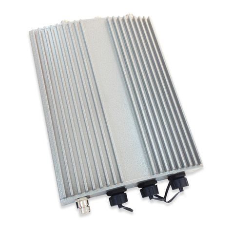
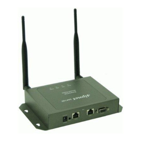
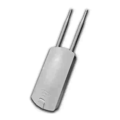
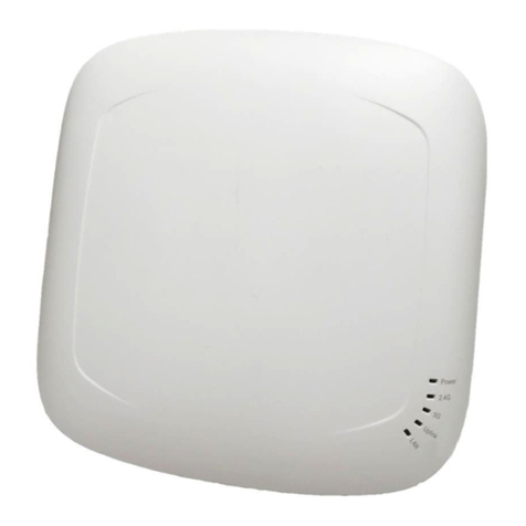
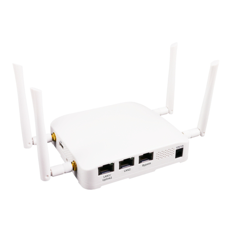
4IPNET EAP200 User manual

EAP200
V1. 0 0

User’s Manual
E A P 2 0 0 E n t e r p r i s e A c c e s s P o i n t E N G L I S H
1
Copyr i g h t © 4 I P N E T , I N C.
Copyright & Disclaimer
Copyright
The contents of this publication may not be reproduced in any part or as a whole, stored,
transcribed in an information retriev al system, translated into any lang uag e, or transmitted in any
form or by any means, mechanical, mag netic, electronic, optical, photocopying , manual, or
otherwise, without the prior written permission of 4 I P N E T, I N C .
D is c l a im e r
4 I P N E T, I N C . does not assume any liability arising out the application or use of any products, or
software described herein. N either does it conv ey any license under its parent rig hts not the parent
rig hts of others. 4 I P N E T further reserv es the rig ht to ma e chang es in any products described herein
without notice. The publication is subj ect to chang e without notice.
T ra d e m a rk s
4 I P N E T ( 4 ipnet) is a reg istered trademar of 4 I P N E T, I N C . O ther trademar s mentioned in this
publication are used for identification purposes only and may be properties of their respectiv e
owners.

User’s Manual
E A P 2 0 0 E n t e r p r i s e A c c e s s P o i n t E N G L I S H
2
Copyr i g h t © 4 I P N E T , I N C.
Table of Contents
1. B e f o r e Y o u S t a r t ............................................................................................................................. 4
1.1 P r e f a c e ........................................................................................................................................... 4
1.2 D o c u m e n t C o n v e n t i o n s ............................................................................................................... 4
1.3 P a c k a g e C o n t e n t .......................................................................................................................... 5
2 . S y s t e m O v e r v i e w a n d G e t t i n g S t a r t e d ......................................................................................... 6
2 .1 n t r o d u c t i o n o f 4 i p n e t E A P 2 0 0 .................................................................................................. 6
2 .2 D e p l o y m e n t T o p o l o g y ................................................................................................................. 7
2 .3 H a r d w a r e D e s c r i p t i o n ................................................................................................................ 8
2 .4 H a r d w a r e n s t a l l a t i o n ............................................................................................................... 10
2 .5 A c c e s s W e b M a n a g e m e n t n t e r f a c e ......................................................................................... 11
3 . C o n n e c t y o u r A P t o y o u r N e t w o r k .............................................................................................. 15
4 . A d d i n g V i r t u a l A c c e s s P o i n t s ...................................................................................................... 21
5 . S e c u r e Y o u r A P ............................................................................................................................ 23
6 . C r e a t e a W D S B r i d g e b e t w e e n t w o A P s ..................................................................................... 32
7 . W e b M a n a g e m e n t n t e r f a c e C o n f i g u r a t i o n ............................................................................... 34
7 .1 S y s t e m ......................................................................................................................................... 36
7 .1 .1 G e n e r a l ................................................................................................................................. 36
7 .1 .2 N e t w o r k n t e r f a c e ............................................................................................................... 38
7 .1 .3 M a n a g e m e n t ........................................................................................................................ 39
7 .2 A P ................................................................................................................................................ 41
7 .2 .1 V A P O v e r v i e w ...................................................................................................................... 41
7 .2 .2 G e n e r a l ................................................................................................................................ 44
7 .2 .3 V A P C o n f i g u r a t i o n ............................................................................................................. 46
7 .2 .4 S e c u r i t y ................................................................................................................................ 47
7 .2 .5 R e p e a t e r .............................................................................................................................. 51
7 .2 .6 A d v a n c e d ............................................................................................................................. 52
7 .2 .7 A c c e s s C o n t r o l ..................................................................................................................... 54
7 .2 .8 S i t e S u r v e y .......................................................................................................................... 58
7 .3 F i r e w a l l ....................................................................................................................................... 60
7 .3 .1 F i r e w a l l L i s t ......................................................................................................................... 60
7 .3 .2 S e r v i c e ................................................................................................................................. 65
7 .3 .3 A d v a n c e d ............................................................................................................................. 66
7 .4 U t i l i t i e s ....................................................................................................................................... 67
7 .4 .1 C h a n g e P a s s w o r d ................................................................................................................ 67
7 .4 .2 B a c k u p & R e s t o r e ............................................................................................................... 68
7 .4 .3 S y s t e m U p g r a d e .................................................................................................................. 69
User’s Manual
E A P 2 0 0 E n t e r p r i s e A c c e s s P o i n t E N G L I S H
3
Copyr i g h t © 4 I P N E T , I N C.
7 .4 .4 R e b o o t ................................................................................................................................. 70
7 .5 S t a t u s .......................................................................................................................................... 71
7 .5 .1 O v e r v i e w .............................................................................................................................. 71
7 .5 .2 A s s o c i a t e d C l i e n t s ............................................................................................................... 73
7 .5 .3 R e p e a t e r .............................................................................................................................. 74
7 .5 .4 E v e n t L o g ............................................................................................................................ 75
7 .6 O n l i n e H e l p ................................................................................................................................ 76

User’s Manual
E A P 2 0 0 E n t e r p r i s e A c c e s s P o i n t E N G L I S H
4
Copyr i g h t © 4 I P N E T , I N C.
1.B efor e Y ou S tar t
1.1 P ref ace
This manual is intended for system integrators, field engineers, and network administrators to set up
4ipnet’s EAP200 802.11n/b/g 2.4GHz MIMO Access Point in their network environments. It contains step-
by-step procedures and visual examples to guide MIS staff or individuals with basic network system
knowledge to complete the installation.
1.2 Docu men t Con v en tion s
Represents essential steps, actions, or messages that should not be ignored.
Note: Contains related information that corresponds to a topic.
Indicates that clicking this button will save the changes you made, but you must reboot
the system upon the completion of all configuration settings for the changes to take effect.
Indicates that clicking this button will clear what you have set before the settings are
applied.

User’s Manual
E A P 2 0 0 E n t e r p r i s e A c c e s s P o i n t E N G L I S H
5
Copyr i g h t © 4 I P N E T , I N C.
1.3 P ack age Con ten t
The standard package of EAP200 includes:
•4ipnet EAP200 x1
•Quick Installation Guide (QIG) x1
•CD-ROM (with User’s Manual and QIG) x1
•Console Cable x1
•Ethernet Cable x1
•Power Adapter (DC 12V) x1
•Antenna x2
•Screw Pack x1
•Ground Cable x1
It is recommended to keep the original packing materials for possible future shipment when repair or
maintenance is required. Any returned product should be packed in its original packaging to prevent
damage during delivery.

User’s Manual
E A P 2 0 0 E n t e r p r i s e A c c e s s P o i n t E N G L I S H
6
Copyr i g h t © 4 I P N E T , I N C.
2. S y stem O v er v i ew and G etti ng S tar ted
2.1 I n trod u ction of 4ipn et A P 20 0
The 4ipnet EAP200 Enterprise Access Point embedded with 802.11 n/b/g 2.4GHz MIMO radio in dust-
proof metal housing is designed for wireless connectivity in enterprise or industrial environments of all
dimensions. EAP200 makes the wireless communication fast, secure and easy. It supports business
grade security such as 802.1X, and Wi-Fi Protected Access (WPA and WPA2). By pushing a purposely
built button, the 4ipWES (Press-n-Connect) feature makes it easy to bridge wireless links of multiple
EAP200s for forming wider wireless network coverage.
EAP200 also features multiple ESSIDs with VLAN tags and multiple Virtual APs, great for enterprise
applications, such as separating the traffics of different departments using different ESSIDs. The PoE
LAN port can receive power from Power over Ethernet (PoE) sourcing device. Its metal case is IP50 anti-
dust compliant, which means that EAP200 is well suited to WLAN deployment in industrial environments.
Figure 1 Wired and Wireless Network Layout with EAP200s

User’s Manual
E A P 2 0 0 E n t e r p r i s e A c c e s s P o i n t E N G L I S H
7
Copyr i g h t © 4 I P N E T , I N C.
2.2 Deploymen t T opology
Figure 2 Common Network Layout with EAP200s
This above deployment scenario illustrates a deployment example using three access points, AP-1, AP-2,
and AP-3.
•Three EAP200 systems construct a network comprising of wired and wireless segments
•AP-2 plays the role of a wireless bridge.
•All devices share the same DHCP server 192.168.1.1.

User’s Manual
E A P 2 0 0 E n t e r p r i s e A c c e s s P o i n t E N G L I S H
8
Copyr i g h t © 4 I P N E T , I N C.
2.3 H ard w are Description
This section depicts the hardware information including all panel description.
Connector Panel
Figure 3 EAP200 Connector Panel
1 USB Disabled for future usage only.
2 WES Press to start running WES process.
3 Console Attach the serial cable here.
4 LAN1 / LAN2 Attach the Ethernet cable here for connection with wired local networks.
5 Reset Press and hold for more than 10 seconds to reset to factory default
configurations.
6 DC 12V Attach the power socket here.
7 12V 1.5A Attach the power adapter here.
Antenna Panel
Figure 4 EAP200 Antenna Panel
Antenna Connector: Attach the antennas here. The system supports one RF interface
with two SMA connectors.

User’s Manual
E A P 2 0 0 E n t e r p r i s e A c c e s s P o i n t E N G L I S H
9
Copyr i g h t © 4 I P N E T , I N C.
LED Panel
Figure 5 EAP200 LED Panel
1 Power LED LED ON indicates power on; OFF indicates power off.
2 LAN LED LED ON indicates LAN cable connected; OFF indicates no connection; BLINKING
indicates transmitting data.
3 WLAN LED LED ON indicates wireless ready.
4 WDS LED LED ON indicates WDS ready.
5 WES LED To indicate WES status.
Master Slave
WES Start LED BLINKING SLOWLY LED BLINKING QUICKLY
WES Success LED ON constantly for 5
seconds
LED ON constantly for 5
seconds
WES Fail LED OFF LED OFF
6 USB LED Disabled for future usage only.

User’s Manual
E A P 2 0 0 E n t e r p r i s e A c c e s s P o i n t E N G L I S H
10
Copyr i g h t © 4 I P N E T , I N C.
2.4 H ard w are I n stallation
Please follow the steps mentioned below to install the hardware of EAP200:
1. Place the EAP200 at the best location.
The best location for EAP200 is usually at the center of your intended wireless network.
2. Connect the EAP200 to your network device.
Connect one end of the Ethernet cable to LAN port of EAP200 and the other end of the cable to a
switch, a router, or a hub. EAP200 is then connected to your existing wired LAN network.
3. There are two ways to supply power over to EAP200.
a) Connect the DC power adapter to the EAP200 power socket.
b) EAP200 LAN port is capable of transmitting DC currents. Connect an IEEE 802.3af-compliant
PSE device (e.g. a PoE-switch) to the LAN port of EAP200 with the Ethernet cable.
Now, the Hardware Installation is complete.
•Please only use the power adapter supplied with the EAP200 package. Using a different
power adapter may damage this system.
•To double verify the wired connection between EAP200 and you switch / router / hub, please
also check the LED status indicator of the respective network devices.

User’s Manual
E A P 2 0 0 E n t e r p r i s e A c c e s s P o i n t E N G L I S H
11
Copyr i g h t © 4 I P N E T , I N C.
2.5 A ccess W eb M an agemen t I n terf ace
4ipnet EAP200 supports web-based configuration. Upon the completion of hardware installation, EAP200
can be configured through a PC by using its web browser such as Mozilla Firefox 2.0 (and higher) or Internet
Explorer version 6.0 (and higher).
The default values of the EAP200’s LAN IP Address and Subnet Mask are:
IP Address: 192.168.1.1
Subnet Mask: 255.255.255.0
Figure 6 Example of entering EAP200's default IP Address into a web browser
•To access the web management interface (WMI), connect the administrator PC to the LAN port of
EAP200 via an Ethernet cable. Then, set a static IP Address on the same subnet mask as the
EAP200 in TCP/IP settings of your PC, such as the following example:
IP Address: 192.168.1.100
Subnet Mask: 255.255.255.0
Note: Please note that the IP Address used should not overlap with the IP Addresses of
any other device within the same network.
•Launch the web browser on your PC and enter the IP Address of the EAP200 (192.168.1.1) at the
address field, and then press Enter. The following Administrator Login Page will then appear. Enter
“admin” for both the Username and Password fields, and then click Login.

User’s Manual
E A P 2 0 0 E n t e r p r i s e A c c e s s P o i n t E N G L I S H
12
Copyr i g h t © 4 I P N E T , I N C.
Figure 7 Administrator Login Page
•After a successful login into EAP200, a System Overview page of the Web Management Interface
(WMI) will appear.
Figure 8 The Web Management Interface - System Overview Page

User’s Manual
E A P 2 0 0 E n t e r p r i s e A c c e s s P o i n t E N G L I S H
13
Copyr i g h t © 4 I P N E T , I N C.
•To logout, simply click on the Logout button at the upper right hand corner of the interface to return to
the Administrator Login Page. Click OK to logout.
Figure 9 Logout
Figure 10 Logout Prompt
For security reasons, it is strongly recommended to change the administrator’s password upon the
completion of all configuration settings

User’s Manual
E A P 2 0 0 E n t e r p r i s e A c c e s s P o i n t E N G L I S H
14
Copyr i g h t © 4 I P N E T , I N C.
Please follow the following steps to change the administrator’s password:
Figure 11 Change Password Page
Click on the Utilities main menu button, and then select the Change Password tab.
Enter the old password and then a new password with a length of up to 32 characters, and retype it in
the Re-enter New Password field.
Congratulation!
Now, 4ipnet’s EAP200 is installed and configured successfully.
•It is strongly recommended to make a backup copy of configuration settings.
•After the EAP200’s network configuration is completed, please remember to change the IP
Address of your PC Connection Properties back to its original settings in order to ensure that
your PC functions properly in its real network environments.

User’s Manual
E A P 2 0 0 E n t e r p r i s e A c c e s s P o i n t E N G L I S H
15
Copyr i g h t © 4 I P N E T , I N C.
3. Connec t y ou r P to y ou r N etw or k
The following instructions depict how to establish the wireless coverage of your network. The AP will
connect to the network through its LAN port and provide wireless access to your network.
After having prepared the EAP200’s hardware for configuration, set the TCP/IP settings of administrator’s
computer to have a static IP Address of 192.168.1.10 and Subnet Mask of 255.255.255.0.
Step 1: Configuring the AP’s System Information
Enter the AP’s default IP Address (192.168.1.1) into the URL of a web browser.
Login via using Username: admin and Password: admin.
The WMI appears as shown below.
Figure 12 Web Management Interface Main Page (System Overview)

User’s Manual
E A P 2 0 0 E n t e r p r i s e A c c e s s P o i n t E N G L I S H
16
Copyr i g h t © 4 I P N E T , I N C.
From here, click on the System icon to arrive at the following page. On this Page you can make
entries to the Name, Description, and Location fields as well as set the device’s time.
Figure 13 System Information Page
There are two methods of setting up the time: Manual (indicated by the option Set Date & Time) and
NTP.
The default is Manual and requires individual setup every time the system starts up. Simply choose a
time zone and set the time accordingly. When finished, click SAVE.
Figure 14 Manually Time Setup
The alternative is NTP. Upon selecting NTP under the Time field, the configuration changes to allow
up to two NTP servers. Simply enter a local NTP server’s IP Address (if available) or search online
for an NTP server nearest you. Set the time zone and click SAVE.

User’s Manual
E A P 2 0 0 E n t e r p r i s e A c c e s s P o i n t E N G L I S H
17
Copyr i g h t © 4 I P N E T , I N C.
Figure 15 NTP Setup
Step 2: Configuring the AP’s Network Settings
While still on this Page, click on the Network Interface tab to begin configuration of the network
settings.
Figure 16 Network Settings Page
If the deployment decides the AP will be getting dynamic IP Addresses from the connected network,
set Mode to DHCP; otherwise, set Mode to Static and fill in the required fields marked with a red
asterisk (IP Address, Netmask, Gateway, and Primary DNS Server) with the appropriate values for
the network. Click SAVE when you are finished to save changes that have been made.

User’s Manual
E A P 2 0 0 E n t e r p r i s e A c c e s s P o i n t E N G L I S H
18
Copyr i g h t © 4 I P N E T , I N C.
Step 3: Configure the AP’s Wireless General Settings
Click on the Wireless icon followed by the General tab. On this page we only need to choose the
Band and Channel that we wish to use.
Figure 17 Wireless General Settings Page
On this page, select the Band with which the AP is to broadcast its signal. The rest of the fields are
optional and can be configured at another time. Click SAVE if any changes have been made.

User’s Manual
E A P 2 0 0 E n t e r p r i s e A c c e s s P o i n t E N G L I S H
19
Copyr i g h t © 4 I P N E T , I N C.
Step 4: Configuring Wireless Coverage (VAP-1)
To setup the AP’s wireless access, refer to the following VAP-1 configuration (other VAP configuration
can refer to the same setup steps as done for VAP-1). Click on the Overview tab to proceed.
Figure 18 Virtual AP Overview Page
On this page click the hyperlink in the row and column that corresponds with VAP-1’s State. This will
bring up the following page.
Figure 19 VAP Configuration Page (VAP-1 shown)
Other manuals for EAP200
2
Table of contents
Other 4IPNET Wireless Access Point manuals

4IPNET
4IPNET EAP210 User manual

4IPNET
4IPNET EAP200 User manual

4IPNET
4IPNET EAP110 User manual

4IPNET
4IPNET EAP260 User manual

4IPNET
4IPNET OWL530 User manual

4IPNET
4IPNET EAP330 User manual

4IPNET
4IPNET EAP727 User manual

4IPNET
4IPNET EAP737 User manual

4IPNET
4IPNET EAP740 User manual

4IPNET
4IPNET OWL500 User manual

4IPNET
4IPNET EAP738 User manual

4IPNET
4IPNET EAP100 User manual

4IPNET
4IPNET EAP705 User manual

4IPNET
4IPNET EAP210 User manual

4IPNET
4IPNET EAP706 User manual

4IPNET
4IPNET EAP220 User manual

4IPNET
4IPNET EAP757 V1.00 User manual

4IPNET
4IPNET EAP727 User manual

4IPNET
4IPNET EAP747 User manual

4IPNET
4IPNET EAP200 User manual