4IPNET OWL800 User manual

IEEE 802.11 b/g Outdoor AP/Bridge
(Support IEEE802.11a Client Backhaul)
Models:
OWL800 V1.00
OWL2000 V1.00
HSG800 V1.00

User’s Manual
IEEE802.11 b/g OutdoorAP/Bridge (Support IEEE802.11a Client Backhaul) OWL800 / OWL2000 / HSG800
ENGLISH
Copyright & Disclaimer
Copyright
The contents of this publication may not be reproduced in any part or as a whole, stored, transcribed in
an information retrieval system, translated into any language, or transmitted in any form or by any means,
mechanical, magnetic, electronic, optical, photocopying, manual, or otherwise, without the prior written
permission of 4IPNET, INC.
Disclaimer
4IPNET, INC. does not assume any liability arising out the application or use of any products, or software
described herein. Neither does it convey any license under its parent rights not the parent rights of others.
4IPNET further reserves the right to make changes in any products described herein without notice. The
publication is subject to change without notice.
Trademarks
4IPNET (4ipnet) is a registered trademark of 4IPNET, INC. Other trademarks mentioned in this publication
are used for identification purposes only and may be properties of their respective owners.

User’s Manual
IEEE802.11 b/g OutdoorAP/Bridge (Support IEEE802.11a Client Backhaul) OWL800 / OWL2000 / HSG800
ENGLISH
Regulatory Information
The device contains two radio modules inside.Although the model of the radio modules themselves has obtained
the FCC modular approval, independently the whole system (with the antennas and power supplier installed) has
been tested and evaluated again by a certified laboratory for the verification of FCC, CE and NCC compliances.
This device requires professional installation. Installers please refer to the caution statements under each
regulatory section to make sure the final installation meet the regulation within you territory. If you are in the North
America, please read the caution statements in FCC section. If you are in the Europe countries, please read the
caution statements under CE. And if you are in Taiwan, please read the Chinese statements under NCC. In addition,
it is important for all to read the following Safety Information first.
Safety Information
All models of OWL800, OWL2000, and HSG800 have been evaluated to, and conforms to the product safety specifications of
EN:60950:2001+A11:2004.
Caution:
This product was qualified under test conditions that included the use of the power supplying equipment. To ensure
regulatory and safety compliance, use only the provided power supplying equipment and install them properly.
To prevent electrical shock, this device may require a grounding conductor in the line cord. Connect the unit to a grounding
type ac wall outlet using the power supplying equipment supplied with the unit.
To avoid the risk of electric shock and for a safety outdoor installation, you may need other items, such as surge arrestors.
To avoid the risk of electric shock from lightening, do not install or use this product during an electrical storm.
Operate and install this product as described in this manual. This device must be installed and used in strict accordance
with the manufacturer's instructions.
Do not open the device casing. Do not perform any servicing other than that contained in the installation and
troubleshooting instructions. Refer all servicing to qualified service personnel.

User’s Manual
IEEE802.11 b/g OutdoorAP/Bridge (Support IEEE802.11a Client Backhaul) OWL800 / OWL2000 / HSG800
ENGLISH
FCC Regulatory Information (for US)
FCC Certification
OWL800, HSG800 and OWL2000 use the same circuitry and housing except the billing and bandwidth management. The
devices operate in the 2.4 GHz and 5.725 - 5.85 bands. They are evaluated and certified according to FCC Rules Part 15
subpart C under one granted FCC-ID: VZ9090001.
FCC Compliance Information
This device complies with Part 15 of the FCC Rules. Operation is subject to the following two conditions: (1) This device may not
cause harmful interference, and (2) this device must accept any interference received, including interference that may cause
undesired operation.
FCC Radiation Exposure Statement:
This equipment complies with FCC radiation exposure limits set forth for an uncontrolled environment.
For complying with the FCC radio frequency exposure requirements, the following antenna installation and device
operating configurations must be satisfied:
The device must be professionally installed on a fixed or permanent structure with a separation distance of at
least 20cm from all persons.
This device and its antennas must not be co-located or operating in conjunction with any other antenna or
transmitter.
Any changes or modifications not expressly approved by the party responsible for compliance could void the
user’s authority to operate this equipment.
FCC Class B Statement
This equipment has been tested and found to comply with the limits for a Class B digital device, pursuant to Part 15 of the FCC
Rules. These limits are designed to provide reasonable protection against harmful interference in a residential installation. This
equipment generates and uses radio frequency energy and, if not installed and used in accordance with the instructions, may
cause interference to radio communications. However, there is no guarantee that interference will not occur in a particular
installation. If this equipment does cause interference to radio or television reception, which can be determined by turning the
equipment off and on, the user is encouraged to try to correct the interference by one or more of the following measures:
Reorient or relocate the receiving antenna or cable input device.
Increase the separation between the equipment and receiver.
Connect the equipment into an outlet on a circuit different from that to which the receiver is connected.
Consult the dealer or an experienced radio/TV technician for help.

User’s Manual
IEEE802.11 b/g OutdoorAP/Bridge (Support IEEE802.11a Client Backhaul) OWL800 / OWL2000 / HSG800
ENGLISH
CE Regulatory Information (for Europe)
Declaration of Conformity with Regard to the 1999/5/EC (R&TTE Directive) for
European Community, Switzerland, Norway, Iceland, and Liechtenstein
Models: OWL800, HSG800 and OWL2000
All three models have been tested and passed the requirements of the following standards, and hence fulfills the EMC and safety
requirements of R&TTE Directive within the CE marking requirement.
• Radio: EN 300.328:2006
• Radio: EN 50392:2004
• EMC: EN 301.489-1:2005, EN 301.489-17:2002,
• EMC: EN 55022:2006 Class B, EN 55024:1998 + A1:2001 + A2:2003 including the followings:
EN 61000-3-2, EN 61000-3-3.
EN 61000-4-2, EN 61000-4-3, EN 61000-4-4,
EN 61000-4-5, EN 61000-4-6, EN 61000-4-11
• Safety: EN 60950-1:2001 + A11:2004,
Caution:
This declaration is only valid for configurations (combinations of software, firmware, and hardware) provided and supported
by 4ipnet Inc. The use of software or firmware not provided and supported by 4ipnet Inc. may result in the equipment no
longer being compliant with the regulatory requirements.
European standards dictate maximum radiated transmit power of 100mW EIRP and frequency range 2.400-2.4835 GHz.
This equipment is intended to be used in all EU and EFTA countries. Outdoor use may be restricted to certain frequencies
and/or may require a license for operation. Contact your local regulatory authority for compliance.

User’s Manual
IEEE802.11 b/g OutdoorAP/Bridge (Support IEEE802.11a Client Backhaul) OWL800 / OWL2000 / HSG800
ENGLISH
NCC Regulatory Information (for Taiwan)
NCC 基本規定項目 :
根據 NCC 低功率電波輻射性電機管理辦法 規定:
第十二條 經型式認證合格之低功率射頻電機,非經許可,公司、商號或使用者均不得擅自變更頻率、加
大功率或變更原設計之特性及功能。
第十四條
低功率射頻電機之使用不得影響飛航安全及干擾合法通信;經發現有干擾現象時應立即停用,
並改善至無干擾時方得繼續使用。
前項合法通信,指依電信法規定作業之無線電通信。
低功率射頻電機須忍受合法通信或工業、科學及醫療用電波輻射性電機設備之干擾。
NCC 其他注意項目 (NCC Caution) :
一、本產品(OWL800, HSG800, OWL2000)及外接天線僅限於專業安裝,並限於固定式、點對點之操作。本產品是設
計為專業用、防水、防風、防銹、堅固之工業級產品;其銷售對象限於有發射器專業安裝技術之工程單位或無線系統
之專業整合商。
二、本產品(OWL800, HSG800, OWL2000)內建兩個無線模組(型號CM9),其最高輸出功率為19dBm。設定介面所提
供的功率變更只能用於調降發射功率,也就是說,設定在最高時(Highest),只會達19 dBm,設定的改變不會加大無
線模組之發射功率。
三、本產品(OWL800, HSG800, OWL2000)雖然有介面可改設內建無線模組的發射頻道,以避免與其它鄰近無線設備
衝突;但介面上所可選之頻道,是根據販售當地法令有所限制。例如,在台灣市場及在北美市場的產品,2.4G範圍只
有11個頻道在介面上可選,使用者無法將發射頻道設為其他在歐、日可選而在台灣所不允許之頻道。
四、本產品(OWL800, HSG800, OWL2000)附有隨機所附手冊,包含以上所有繁體中文警告訊息。專業使用者與安裝
者有責遵循NCC規定。專業使用者與安裝者若有自行變動產品,違規使用當地法規不允許頻率、功率,必須承擔法律
責任並負責賠償受害用戶之一切損失。

User’s Manual
OWL800 / OWL2000 / HSG800 ENGLISH
© 2008 4IPNET, INC.
1
Table of Contents
Copyright & Disclaimer.....................................................................................................................................i
Regulatory Information....................................................................................................................................... ii
FCC Regulatory Information (for US)...................................................................................................................... iii
CE Regulatory Information (for Europe)...................................................................................................................iv
NCC Regulatory Information (for Taiwan).................................................................................................................v
1. Before You Start ............................................................................................................................3
1.1 Preface ....................................................................................................................................................3
1.2 Document Convention............................................................................................................................3
2. System Overview ...........................................................................................................................2
2.1 Introduction of OWL800 ........................................................................................................................2
2.2 System Concept ......................................................................................................................................2
3. Base Installation...........................................................................................................................4
3.1 Hardware Installation..............................................................................................................................4
3.1.1 Package Contents..........................................................................................................................................4
3.1.2 Panel Function Descriptions .........................................................................................................................5
3.1.3 Hardware Installation....................................................................................................................................6
3.2 Software Configuration...........................................................................................................................7
3.2.1 Instruction of Web Management Interface....................................................................................................7
3.2.2 User Login Portal Page...............................................................................................................................10
3.2.3 Basic Configuration....................................................................................................................................12
3.2.4 Common Settings........................................................................................................................................16
4. Menu Configuration (AP & Gateway Mode).............................................................................20
4.1 System...................................................................................................................................................24
4.1.1 General........................................................................................................................................................24
4.1.2 Network Interface .......................................................................................................................................27
4.1.3 Management................................................................................................................................................32
4.1.4 VLAN Overview.........................................................................................................................................34
4.1.5 VLAN Configuration..................................................................................................................................36
4.1.6 Walled Garden.............................................................................................................................................39
4.1.7 Mode...........................................................................................................................................................41
4.2 AP .........................................................................................................................................................42
4.2.1 Overview.....................................................................................................................................................42
4.2.2 General........................................................................................................................................................45
4.2.3 VAP Configuration......................................................................................................................................46
4.2.4 Security.......................................................................................................................................................47
4.2.5 Advanced....................................................................................................................................................51
4.2.6 Access Control............................................................................................................................................52
User’s Manual
OWL800 / OWL2000 / HSG800 ENGLISH
© 2008 4IPNET, INC.
2
4.3 WDS......................................................................................................................................................54
4.3.1 Overview.....................................................................................................................................................54
4.3.2 General........................................................................................................................................................55
4.3.3 WDS Configuration....................................................................................................................................56
4.3.4 WDS Discovery..........................................................................................................................................58
4.4 User.......................................................................................................................................................59
4.4.1 Local ...........................................................................................................................................................59
4.4.2 RADIUS......................................................................................................................................................62
4.4.3 On-demand..................................................................................................................................................64
4.4.4 Policy..........................................................................................................................................................69
4.4.5 Firewall.......................................................................................................................................................71
4.4.6 Route...........................................................................................................................................................73
4.4.7 802.1X.........................................................................................................................................................74
4.5 Utilities..................................................................................................................................................75
4.5.1 Change Password........................................................................................................................................75
4.5.2 Import & Export..........................................................................................................................................76
4.5.3 Backup & Restore.......................................................................................................................................77
4.5.4 System Upgrade..........................................................................................................................................78
4.5.5 Reboot.........................................................................................................................................................79
4.5.6 Scan.............................................................................................................................................................80
4.5.7 Upload Certificate.......................................................................................................................................81
4.6 Status.....................................................................................................................................................82
4.6.1 Overview.....................................................................................................................................................82
4.6.2 WDS List ....................................................................................................................................................85
4.6.3 Antennas .....................................................................................................................................................86
4.6.4 Associated Clients.......................................................................................................................................87
4.6.5 Event Log....................................................................................................................................................88
4.6.6 Online Users ...............................................................................................................................................89
4.6.7 User Log .....................................................................................................................................................90
Appendix A. Session Limit and Session Log.......................................................................................91
Appendix B. 802.1X Support................................................................................................................93

User’s Manual
OWL800 / OWL2000 / HSG800 ENGLISH
© 2008 4IPNET, INC.
3
1. Before You Start
1.1 Preface
This manual is intended for using by system integrators, professional field engineers and network administrators to
help them set up OWL800 for their network deployment. It contains step by step procedures and pictures to guide
users with basic network system knowledge to complete the installation.
The IEEE 802.11 b/g Outdoor AP/Bridge (Support IEEE802.11a Client Backhaul) is a rugged multi-mode
dual-radio outdoor access point, specifically designed for building municipal or campus wide wireless networks in
harsh outdoor environments. The entry model OWL800 is deployed as a traditional multi-wireless Access Point (AP)
or a backhaul. The second model HSG800, can be used as an Outdoor Wireless Gateway with built-in Hotspot
Access Control and Billing features. The OWL2000 is purely used for building point-to-point bridges. Some of the
optional features (such as billing) are on or off depending on the model. Please refer to the optional feature lists
provided separately. In this manual, all the optional featured are covered. In the following manual, we will refer the
device as “OWL800” or “the system” for the convenience.
Model Description
OWL800 This is the base model. Its firmware can be upgraded to be HSG800 or OWL2000
when optional software feature is purchase. The base firmware supportAP/Bridge
and Gateway operation mode.
HSG800 This model consists of all the features of OWL800, plus the Hotspot billing &
payment function.
OWL2000 This model turn an OWL800 first radio card from anAP into another
backhaul/bridge radio card. Traffic over multiple air links will be aggregated to
achieve better throughput and reliability.
1.2 Document Convention
The following information provides the details of conventions used in this manual. In the following manual, we will
refer the device as “OWL800” or “the system” for the convenience.
For cautionary statements or warning requiring special attention by readers, a text box with italic font will be used:
Warning: For security purposes, you should immediately change the administrator’s password.
When any of the button and symbol shown below is selected, the following action will be executed accordingly:

User’s Manual
OWL800 / OWL2000 / HSG800 ENGLISH
© 2008 4IPNET, INC.
4
Return to system Home page.
Logout the system.
Apply all configurations.
Clear all configurations and not to activate them.
Clear settings entered by clicking this button.
* The red asterisk indicates information in this field is compulsory.
Note: Screen captures and pictures used in this manual may be displayed in part or in whole or similar products,
and may vary or differ slightly from the actual product, depending on versioning and menu accessed.

User’s Manual
OWL800 / OWL2000 / HSG800 ENGLISH
© 2008 4IPNET, INC.
2
2. System Overview
2.1 Introduction of OWL800
The IEEE 802.11 b/g Outdoor AP/Bridge (Support IEEE802.11a Client Backhaul) series (referred as OWL800 or
the system in this manual) is a rugged multi-mode dual-radio outdoor access point, specifically designed for building
municipal or campus wide wireless networks in harsh outdoor environments. There are two System Modes that can
be used for dual purposes. First, it can be deployed as a traditional multi-wireless Access Point (AP) or a Relay.
Secondly, it can be used as an Outdoor Wireless Gateway with Built-in Hotspot Access Control and Billing features
(* an optional feature).
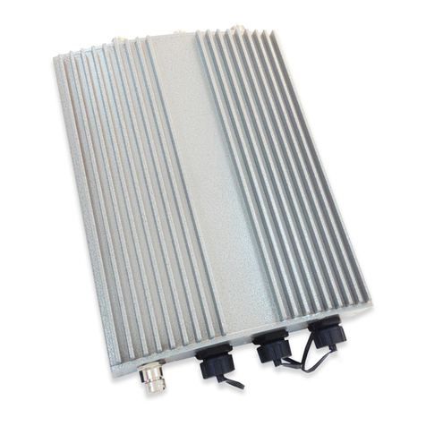
The metal sealed OWL800 is weatherproof. Coming with a mounting kit, it can be mounded on a pole or on wall.
This Quick Installation Guide provides instructions and reference material for getting started with OWL800 (as well
as the other two models).
OWL800’s rust-free die-cast Aluminum housing is IP68 compliant and high wind load resilient. All the components
are designed to operate in a wide range of temperature. The on-board surge protection provides the device up to
15KV surge immunity. The OWL800 delivers an excellent outdoor WLAN solution.
2.2 System Concept
The System contains two radio modules. Two 100mW modules are WNC’s CM9, which are tested to be modular
FCC and CE compliant. The first card is mainly used for serving clients at “b/g” mode. The second Radio module is
used for building point-to-point or the back haul connection in “a” mode.
OWL800 is a cost-effective choice as well as a flexible solution for constructing serviceable wireless network.
Designed by the leading hotspot appliance provider, 4ipnet OWL800 behaves more than a wireless router when it is
in Gateway mode. Not only it supports NAT, DHCP and firewall, it also has AAA features of a hotspot gateway,
including UAM web login portal and billing plans. Standalone it has local user database for authentication, while at
the same time it can play the role of RADIUS-NAS, authenticating users against ISP’s RADIUS server in the data
center.

User’s Manual
OWL800 / OWL2000 / HSG800 ENGLISH
© 2008 4IPNET, INC.
3
Multi-mode in Operation

User’s Manual
OWL800 / OWL2000 / HSG800 ENGLISH
© 2008 4IPNET, INC.
4
3. Base Installation
3.1 Hardware Installation
3.1.1 Package Contents
The standard package of OWL800 includes:
yOWL800 x 1
yQuick Installation Guide (with User’s Manual and QIG) x 1
yCD-ROM x1
yRJ45-RS232 Console Cable x 1
yPSE x 1
yPowercord x1
yMounting Kit x 1
yWaterproof Connector Pack x 2
yRubber antenna x 4
Note: It is recommended to keep the original packing materials in case of product service requirements. Any
returned product should be packed according to its original package content, together with its relevant packing
materials used for protecting the equipment from damage during delivery.

User’s Manual
OWL800 / OWL2000 / HSG800 ENGLISH
© 2008 4IPNET, INC.
5
3.1.2 Panel Function Descriptions
Lower Panel
PoE1 / PoE2: For connecting to the PSE
oIn AP/Relay mode, PoE1 and PoE2 work as LAN ports.
oIn Gateway mode, PoE1 works as a WAN port and PoE2 works as a LAN port.
Console:
oAttach the RJ45-RS232 console cable here.
Upper Panel
This picture represents ANT 1 ~ ANT 4 connectors from right to left when OWL800 chassis (with Mylar) is faced up.
Each of the two radio module (CM9) inside has two antenna connectors for antenna diversity. The required
antenna is antenna ANT1 and antenna ANT2. ANT1 is connected to the “Main” contact point of the first radio
module. ANT2 is connected to the “Main” contact of the second module.
The other two antennas are optional for antenna diversity. The antenna ANT3 is connected to the “Aux” contact point
of the first radio module, while ANT4 is connected to the “Aux” contact point of the second radio module. For further
details on antenna, please refer to the section 4.6.3..

User’s Manual
OWL800 / OWL2000 / HSG800 ENGLISH
© 2008 4IPNET, INC.
6
3.1.3 Hardware Installation
Please follow the steps mentioned below to complete the hardware of OWL800 for configuration.
1. Connect antennas to the required ANT1 and ANT3, which lead to the “Main” contacts of the two radio cards.
2. (Optional) Connect antennas to the requiredANT3 and ANT4, which lead to the “Aux” contacts of the two radio
cards.
3. Connect the PSE (POWER & DATA OUT) to the PoE 2 connector on the lower panel.
4. Connect one end of an Ethernet cable to the PSE (DATA IN) and the other end to a computer.
5. Connect the power cord to the PSE.
6. Power on the PSE in order to supply power to OWL800.
7. Note You must be professional to use a different replacement antenna, and you must following the
code/regulation of your region/country for the installation.
Now, the Hardware Installation has been completed and ready for configuration. It is easier to following the Quick
Installation Guild for the first time to configure the necessary network parameters, such as the IP address.
Note: It is recommended to keep the original packing materials in case of product service requirements. Any
returned product should be packed according to its original package content, together with its relevant packing
materials used for protecting the equipment from damage during delivery.

User’s Manual
OWL800 / OWL2000 / HSG800 ENGLISH
© 2008 4IPNET, INC.
7
3.2 Software Configuration
3.2.1 Instruction of Web Management Interface
OWL800 provides the web management interface for configuration. OWL800 is a multi-mode system which can be
configured as either an access point (AP/Relay Mode with RF1 in AP), a relay (AP/Relay Mode with RF1 in WDS),
or a gateway that clients can associate on it based on your needs. It is required to follow the respective installation
procedures provided to properly set up the desired mode of this system.
After completing hardware installation, the administrator can configure the OWL800 via web browsers.
The default IP address and Subnet Mask of different modes are as follows:
Mode AP/Relay Gateway
IP Address 192.168.2.1 192.168.1.1
Subnet Mask 255.255.255.0 255.255.255.0
Default Gateway 192.168.2.254 192.168.1.254
Enter “admin” as the default Username and “admin” as the default Password and click Login to continue.
Note: If you are unable to get to the login screen, please check the IP address used. The IP address should be in
the same subnet of the default gateway. For using static IP in TCP/IP setting, set a static IP address such as
192.168.1.x for your network interface and then open a new browser again.

User’s Manual
OWL800 / OWL2000 / HSG800 ENGLISH
© 2008 4IPNET, INC.
8
¾Main Menu: provides detailed configuration pages for administrators to configure the system manually. Please
refer to Section 4. - Main Menu for more information.
Gateway Mode

User’s Manual
OWL800 / OWL2000 / HSG800 ENGLISH
© 2008 4IPNET, INC.
9
AP Mode

User’s Manual
OWL800 / OWL2000 / HSG800 ENGLISH
© 2008 4IPNET, INC.
10
3.2.2 User Login Portal Page
To be granted the network access via OWL800, clients have to be authenticated by the system first via entering the
correct usernames and passwords in the User Login Portal Page as shown below. The local account generated
previously in the Setup Wizard section is used as the example to illustrate this procedure.
Step 1:
Connect a client’s PC to OWL800 via any one of the LAN Ports. The IP address will be assigned to the PC
automatically via DHCP.
Step 2:
Verify New Local Account:
To verify whether the configuration with DHCP via the Setup Wizard is done properly, firstly, connect a client’s PC
from the system to LAN1 Port. The device will get an IP address automatically via DHCP.
Next, open a web browser and access any URL, and then the default User Login Page will appear.
Enter the username and password of the local user account generated by Setup Wizard previously (e.g.
“test@local” as the Username and “test” as the Password), then click Login.
Note:
1. OWL800 supports both local built-in user database and external authentication database, such as RADIUS and
LDAP. Thus, by entering the full username, the system will automatically identify which authentication server is used.
Exception: The postfix can be omitted only when the default authentication option is used; “local” is the default
authentication option of the system. You may therefore enter either ‘test’, or ‘test@local in the username field for
the previous example.
2. The format of a valid Username is: UserId@postfix, where UserId is the User ID, and postfix is a name for the
chosen authentication option.

User’s Manual
OWL800 / OWL2000 / HSG800 ENGLISH
© 2008 4IPNET, INC.
11
Step 3:
The Login Success Page will appear after a client is authenticated by the system and logs in successfully. In the
meantime, successful login means OWL800 has been installed and configured properly.
This manual suits for next models
2
Table of contents
Other 4IPNET Wireless Access Point manuals

4IPNET
4IPNET EAP717 User manual

4IPNET
4IPNET EAP260 User manual

4IPNET
4IPNET EAP210 User manual

4IPNET
4IPNET EAP760 User manual

4IPNET
4IPNET EAP705 User manual

4IPNET
4IPNET OWL530 v1.00 User manual

4IPNET
4IPNET OWL300 User manual

4IPNET
4IPNET EAP210 User manual

4IPNET
4IPNET EAP757 V1.00 User manual

4IPNET
4IPNET EAP701 User manual

4IPNET
4IPNET EAP200 User manual

4IPNET
4IPNET EAP100 User manual

4IPNET
4IPNET EAP260 User manual

4IPNET
4IPNET EAP110 User manual

4IPNET
4IPNET EAP738 User manual

4IPNET
4IPNET OWL500 User manual

4IPNET
4IPNET EAP210 User manual

4IPNET
4IPNET EAP210 User manual

4IPNET
4IPNET OWL610 Operator's manual

4IPNET
4IPNET OWL530 User manual