manuals.online logo
Brands
  1. Home
  2. •
  3. Brands
  4. •
  5. ABB
  6. •
  7. Accessories
  8. •
  9. ABB Ability User manual

ABB Ability User manual

IMPORTANT! Read these instructions in
their entirety before installing the ABB
Ability™ Smart Sensor, generation 2
with aluminum clamping bracket.
—
INSTALLATION GUIDE
ABB AbilityTM Smart Sensor, generation 2
Installation with aluminum clamping bracket
CAUTION
Asset surface temperature hazard. The external
surface of an electric motor may reach tempera-
tures which can cause discomfort, burns or injury
to individuals who come into contact with the hot
surface. For safety reasons the asset should be
switched off and allowed to cool before attempting
to install the sensor. Asset surface temperatures
should only be measured with suitable instruments
and not estimated by hand touch or direct skin
contact. Failure to observe this precaution could
result in bodily injury.
Do not replace batteries! Incorrect use of batteries
voids the certifications of the Smart Sensor, such as
hazardous area certifications, safety certifications,
and IP rating. Dispose of used sensors according to
instructions.
WARNING
Only qualified individuals who are familiar with
appropriate national codes, local codes and sound
practices should install, repair or modify electric
motor and/or related accessories. Installation
should conform to appropriate codes and practic-
es. Failure to follow these instructions could result
in serious personal injury, death and/or property
damage.
Electrical live circuit hazard. Do not touch electri-
cally live parts or equipment. For a safe installation,
disconnect, lockout and tagout the asset’s power
supply before installing or servicing the sensor.
ATTENTION
Install as per industry codes and regulations
The Smart Sensor should be installed by technically
qualified personnel. Failure to install the sensor in
compliance with applicable codes and regulations and
according to the manufacturer’s recommendations may
result in electrical shock, fire hazard, unsatisfactory
performance or equipment failure, and may void the
sensor warranty.
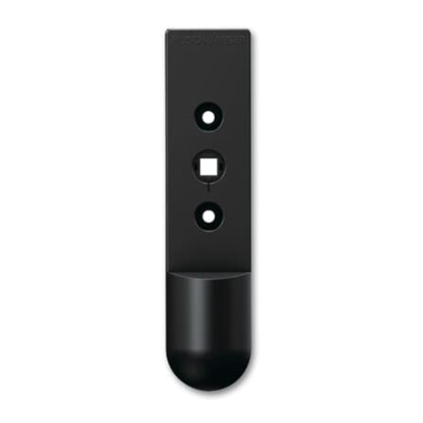
Grounding of sensor
The mounting piece must be grounded if the sensor is
installed in any of the below zones:
• Mines (Group I): Not permitted
• Gas (Group II A, B, C): Zone 1, Zone 2 (Not permitted in
zone zero)
• Dust (Group III): All zones
For grounding, attach a wire using the M6 screw hole.
Installation instructions
Obey the following instructions for the installation of ABB AbilityTM Smart Sensors on assets.
Notes:
• For effective Bluetooth® communication, mount the sensor with a clear line of sight to any communication
devices to be used (your smartphone or a Bluetooth® gateway).
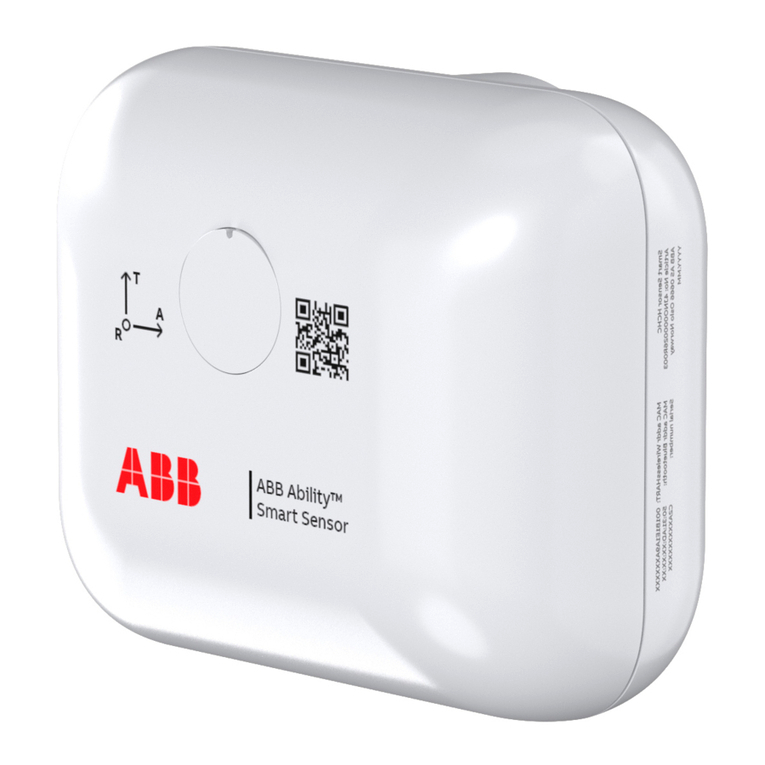
• The mounting orientation must be such that the A-axis on the sensor housing is parallel to the rotating
shaft. If this is not physically possible, the T-axis must be parallel to the rotating shaft.
Mounting position on motor
The sensor must be located between the drive-end and non-drive-end bearings, as near to the center as
possible.
Note: The sensor mount cannot be removed after installation.
Supported motors
This mounting instruction applies for fin-cooled motors equivalent to frame sizes IEC 160–450.
For information on motor types monitored with the ABB AbilityTM Smart Sensor, visit
www.abb.com/smartsensor.
Quick start guide
2ABB ABILITY SMART SENSOR, GENERATION 2 INSTALLATION GUIDE FOR ALUMINUM CLAMPING BRACKET
Step Instructions Additional information
1Install the ABB Ability™ Smart Sensor
Platform App.
The Smart Sensor Platform App can be found in App Store (Apple)
and Google Play Store (Android).
Note: In some countries these stores may not be accessible. For
more information, see www.abb.com/smartsensor.
2 Register in the ABB Ability™ Smart Sensor
Platform App.
- Follow the sign-up link in the app.
- Alternatively, you can sign up on the web portal at
https://smartsensor.abb.com.
- Skip this step if you have already registered.
3 Log in to the ABB Ability™ Smart Sensor
Platform App.
- Create or join an existing organization.
- Follow the instructions on the screen.
4 Install the ABB AbilityTM Smart Sensor. - Make sure that you have the required components.
- Install the sensor according to the installation steps in this manual.
5 Activate the sensor with the ABB Ability™
Smart Sensor Platform App.
- Navigate to the main menu in the app and tap Activate Sensor.
- Follow the instructions displayed on the mobile screen.
6 Commission the asset in the ABB Ability™
Smart Sensor Platform App.
- Navigate to the Commission new asset menu in the app.
- Select the equipment profile you want to monitor.
- Follow the instructions on the screen.
7 Take first measurements and check the
asset condition.
Select the asset and navigate to Load Measurements.
For more detailed instructions, visit www.abb.com/smartsensor.
Instructions for hazardous area
1. Ground the aluminum clamp in hazardous area installations. The aluminum clamp supports grounding by
having another M6 thread on the other end of the clamp.
2. Do the grounding according to local regulations. As a reference, the IEC 60079-14 defines the minimum
diameter for grounding wire as 4 mm2. Maximum length of the M6 threaded screw is 6 mm.
Step 1
Degrease the upper and lower surfaces of the selected fin at
the recommended mounting position.
CAUTION
Review and obey all manufacturer’s instructions and safety
precautions when using degreasing agent.
Installation steps
Step 2
Apply LoctiteTM 454 or equivalent glue evenly along the
entire length of the bracket in two marked places shown in
figure-1. Similarly apply glue evenly to the top of the fin for
the entire length of bracket as shown in figure-2.
CAUTION
Review and obey all manufacturer’s instructions and safety
precautions when using glue.
WARNING
Direct skin exposure to solvents and/or threadlocker could cause discomfort or injury, including, but not limited
to, burning or skin irritation. Use appropriate protective gloves and goggles when performing this task.
ABB ABILITY SMART SENSOR, GENERATION 2 INSTALLATION GUIDE FOR ALUMINUM CLAMPING BRACKET 3
Notes
• Make sure that the bracket is clamped to the cooling fin such that the neighboring fins do not prevent attaching
the sensor.
• If sensor is installed in hazardous area, prepare the clamp with grounding cable before attaching the sensor to the
clamp.
1 Aluminum clamping bracket (revision B with 2 * M6 threads)
2M6 hexagon socket screw (metallic color)
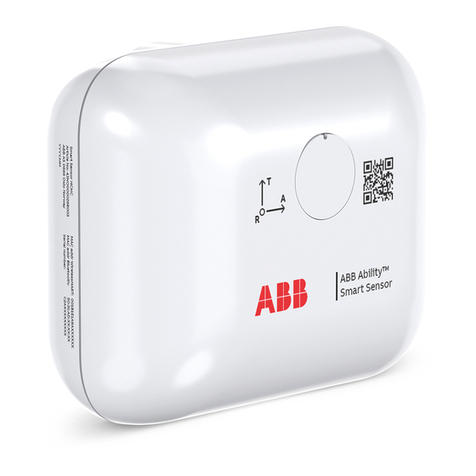
3ABB Ability™ Smart Sensor G2
4Cover for screw hole
5Grounding cable
6¼” - 28 UNF hexagon socket screw (black color)
7
Rubber gloves
8
50 mm long hex bit (5 mm for M6 screw) and torque wrench
-
Other miscellaneous items: Safety goggles, degreasing agent, possibly
threadlocker, and suitable tools and materials to do the grounding if sensor is
installed in hazardous area.
Materials needed for the installation
Step 3
Use a hammer with a rubber or plastic head and insert
the mounting bracket until the edge of the cooling fin
touches the inside face of the bracket.
The groove marked in red in the figure is for direct
contact between the clamp and the motor rib.
Figure-1 Figure-2
9AKK108140 REV E EN 09-09-2022
—
For questions, feedback and support, contact:
Product information
www.abb.com/smartsensor
Support
[email protected]
Subscriptions
https://eu.marketplace.ability.abb/
Step 7
Activate the sensor and commission the asset. See section
“Quick start guide”, steps 5–7.
Note: After commissioning, the sensor has a two-month trial
period with full functionality. After the trial period, you can
continue the usage by activating a subscription acquired from a
local ABB sales unit.
—
We reserve the right to make technical changes
or modify the contents of this document with-
out prior notice. With regard to purchase or-
ders, the agreed particulars shall prevail. ABB
Ltd does not accept any responsibility whatso-
ever for potential errors or possible lack of in-
formation in this document.
We reserve all rights in this document and in
the subject matter and illustrations contained
therein. Any reproduction, disclosure to third
parties or utilization of its
contents – in whole
or in parts – is forbidden
without prior written
consent of ABB Ltd.
Copyright© 2022 ABB
All rights reserved
Step 4
Ground the mounting piece if the sensor is installed in hazardous
areas mentioned on page 1. Bring a grounding wire of minimum
4 mm2diameter on the M6 screw of the mounting piece. After
grounding the mounting piece, measure the resistance between
asset frame and mounting piece. Make sure that the resistance is
below the maximum 1 MΩaccording to IEC 60079-14.
CAUTION
This step is manadatory only for installations in hazardous areas.
Step 5
Fasten the ABB Ability™ Smart Sensor G2 to the mounting
bracket using the metallic colored hexagon M6 socket screw.
Tighten the screw with 10 Nm (7.4 ft-lb) of torque.
Note: In harsh environments, use threadlocker.
Step 6
Make sure that the ABB Ability™ Smart Sensor G2 is mounted
parallel to the rotating shaft by aligning it with the asset fins.
Assemble the cover plate to hide the screw hole.

Other manuals for Ability

4

Other ABB Accessories manuals

ABB TB404 User manual

ABB

ABB TB404 User manual

ABB AP201 User manual

ABB

ABB AP201 User manual

ABB Eden OSSD User manual

ABB

ABB Eden OSSD User manual

ABB CS500 User manual

ABB

ABB CS500 User manual

ABB HS/S4.2.1 User manual

ABB

ABB HS/S4.2.1 User manual

ABB Aztec ATS430 User manual

ABB

ABB Aztec ATS430 User manual

ABB CoreSense User manual

ABB

ABB CoreSense User manual

ABB AquaMaster4 User manual

ABB

ABB AquaMaster4 User manual

ABB CMS-12xLA User manual

ABB

ABB CMS-12xLA User manual

ABB AP200 Series User manual

ABB

ABB AP200 Series User manual

ABB 2CSYD0102B Guide

ABB

ABB 2CSYD0102B Guide

ABB Ability Smart Sensor User manual

ABB

ABB Ability Smart Sensor User manual

ABB AP300 User manual

ABB

ABB AP300 User manual

ABB KEVA 36 G2 Series Parts list manual

ABB

ABB KEVA 36 G2 Series Parts list manual

ABB Relion SMU615 User manual

ABB

ABB Relion SMU615 User manual

ABB 3KXA494400L005 Operating and maintenance manual

ABB

ABB 3KXA494400L005 Operating and maintenance manual

ABB Ability User manual

ABB

ABB Ability User manual

ABB AquaMaster4 User manual

ABB

ABB AquaMaster4 User manual

ABB SCC-C User manual

ABB

ABB SCC-C User manual

ABB 5526A-A02359 User manual

ABB

ABB 5526A-A02359 User manual

ABB ABB-free@home WBI-S-1-xx-WL Series User manual

ABB

ABB ABB-free@home WBI-S-1-xx-WL Series User manual

ABB AquaProbe FEA100 User manual

ABB

ABB AquaProbe FEA100 User manual

ABB LevelMaster 7100 User manual

ABB

ABB LevelMaster 7100 User manual

ABB NIESSEN 8131 User manual

ABB

ABB NIESSEN 8131 User manual

Popular Accessories manuals by other brands

Celsius CELQEB-LS operating instructions

Celsius

Celsius CELQEB-LS operating instructions

MeiTrack ASUF101 user guide

MeiTrack

MeiTrack ASUF101 user guide

aci Room Series Installation & operation instructions

aci

aci Room Series Installation & operation instructions

HAGS NG223S installation instructions

HAGS

HAGS NG223S installation instructions

Star ECONO EC-CCY Operation manual

Star

Star ECONO EC-CCY Operation manual

ULTIMATE SPEED UPBS 12000 A1 Operation and safety notes

ULTIMATE SPEED

ULTIMATE SPEED UPBS 12000 A1 Operation and safety notes

INSTEON TriggerLinc 2843-2 owner's manual

INSTEON

INSTEON TriggerLinc 2843-2 owner's manual

BERG Elite Plus user manual

BERG

BERG Elite Plus user manual

A&D AD-4323 instruction manual

A&D

A&D AD-4323 instruction manual

Pepperl+Fuchs LUC-M10 Safety instructions

Pepperl+Fuchs

Pepperl+Fuchs LUC-M10 Safety instructions

Valore PB02 manual

Valore

Valore PB02 manual

GTV CR-4LED manual

GTV

GTV CR-4LED manual

Bretford M-SUBC Assembly instructions

Bretford

Bretford M-SUBC Assembly instructions

Pepperl+Fuchs R1000 Series manual

Pepperl+Fuchs

Pepperl+Fuchs R1000 Series manual

Rockwell Automation 42JT-C2LAT1-A2 installation instructions

Rockwell Automation

Rockwell Automation 42JT-C2LAT1-A2 installation instructions

Geca CTP21 user manual

Geca

Geca CTP21 user manual

Iget SECURITY M3P10 installation manual

Iget

Iget SECURITY M3P10 installation manual

cozee home 806335 instruction manual

cozee home

cozee home 806335 instruction manual

manuals.online logo
manuals.online logoBrands
  • About & Mission
  • Contact us
  • Privacy Policy
  • Terms and Conditions

Copyright 2025 Manuals.Online. All Rights Reserved.