ABB HVC 100C User manual

—
USER MANUAL
HVC 100C / HVC 150C with
Depot Charge box
User and Operation Manual

Notice
This document contains informationabout one ormoreABB products and may include a
description of or a referenceto one or more standards that may be generally relevant to the ABB
products. The presence ofany such description of a standard or reference to a standard is nota
representation that all ofthe ABB products referenced in this document support all of the features
of the described or referenced standard. In order to determine the specific features supported by a
particular ABB product, thereader should consult the product specifications for the particular ABB
product.
ABB may have one or more patents or pending patent applications protecting the intellectual
propertyin the ABB products described in this document.
The information in this document is subject to change without noticeand shouldnot be construed
as a commitment by ABB. ABB assumes no responsibility for any errors that may appear in this
document.
In no event shall ABB be liable for direct,indirect, special, incidental or consequential damages of
any nature or kind arising fromthe use ofthis document, nor shall ABB be liable for incidental or
consequential damages arising from use of any software or hardware described in this document.
This document and parts thereof mustnot be reproduced or copied without written permission
from ABB, and the contents thereof must not be imparted to a third party nor used for any
unauthorized purpose.
Copyrights
All rights to copyrights, registeredtrademarks, andtrademarks reside with their respective
owners.
Copyright © 2021ABB.

All rights reserved.
Contents
Glossary...............................................................................................................................................................4
1 Introduction...................................................................................................................................................5
1.1 Preface................................................................................................................................................................5
1.2 Intended use of this document.....................................................................................................................5
1.3 Intended use of thecharger..........................................................................................................................5
1.4 Owner responsibilities....................................................................................................................................6
1.5 Signs....................................................................................................................................................................7
1.6 Safety regulations............................................................................................................................................8
2 Description of the product...........................................................................................................................9
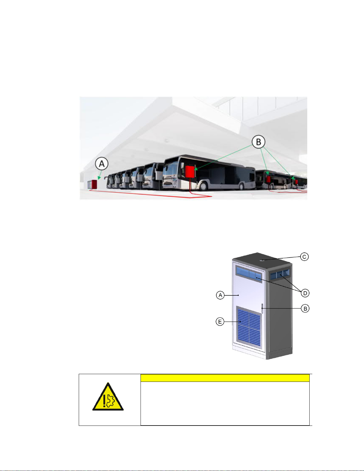
2.1 Overview of the system..................................................................................................................................9
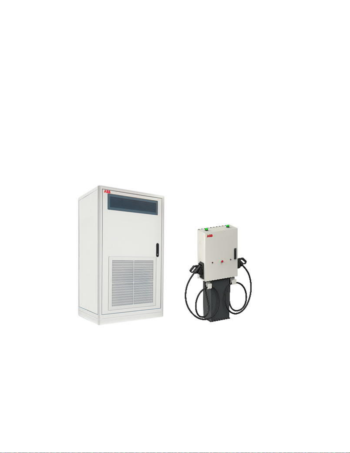
2.2 Power Cabinet...................................................................................................................................................9
2.3 Dual Depot Charge Box.................................................................................................................................10
2.4 Charger configurations .................................................................................................................................11
2.5 Authorization to charge.................................................................................................................................11
3 Charging instruction...................................................................................................................................12
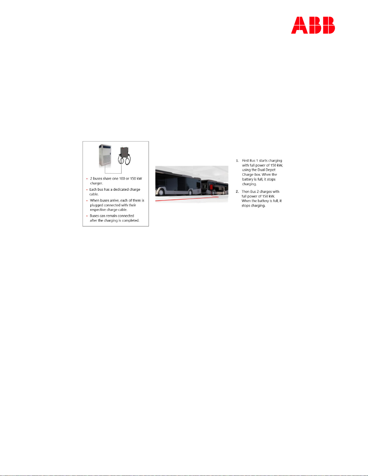
3.1 Charging with one Dual Depot Charge Box .............................................................................................12
3.2 Emergency stop..............................................................................................................................................13
4Operator Instructions.................................................................................................................................14
4.1 Cleaning thePower Cabinet and the Dual Depot Charge Box.............................................................14
4.2 Preventive maintenance................................................................................................................................14
4.2.1 Serviceinspection of the cabinets...........................................................................................14
4.2.2 Emergency stop inspection.......................................................................................................15
4.2.3 Special inspections......................................................................................................................15
4.3 Problem solving..............................................................................................................................................15
4.3.1 Overview of the Power Cabinet.................................................................................................15
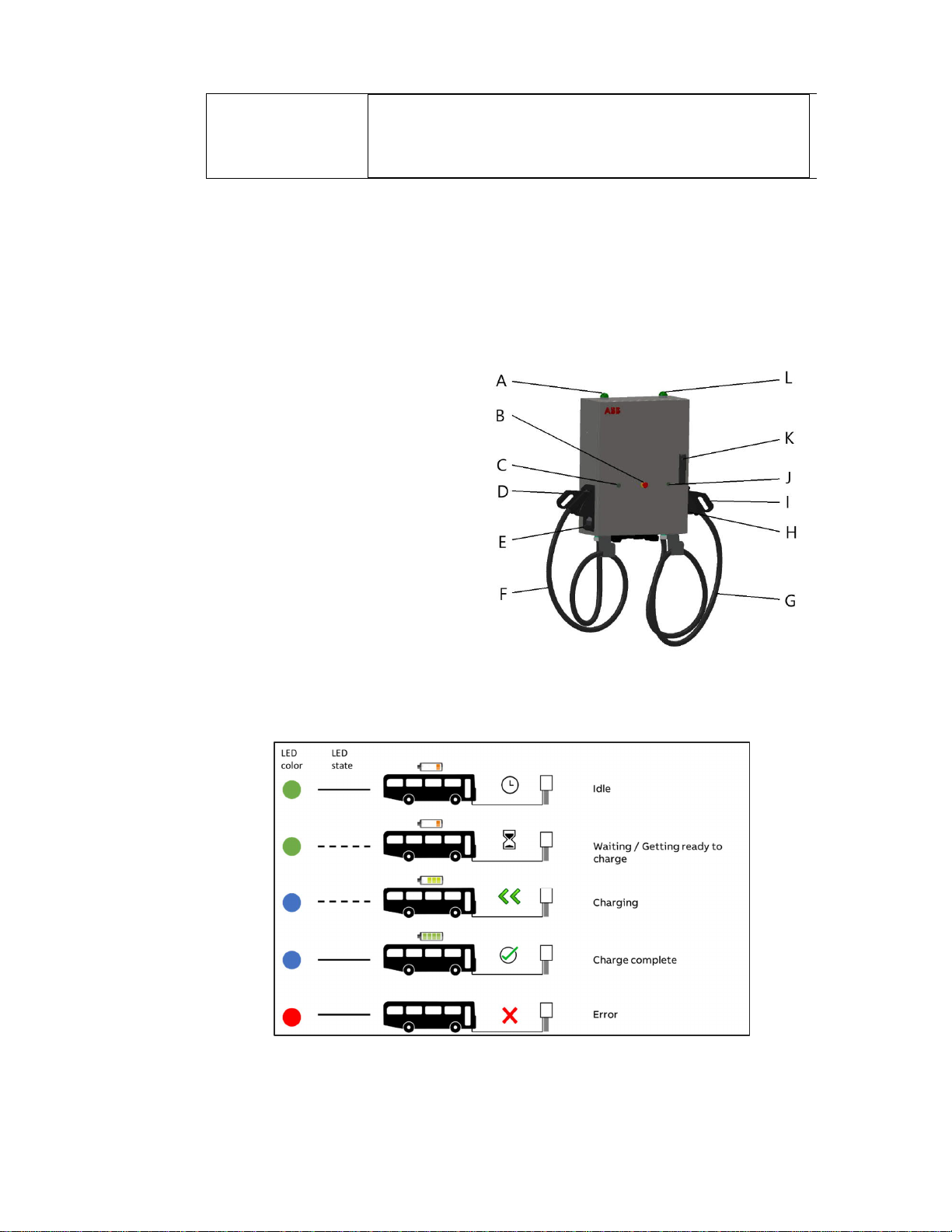
4.3.2 Overview of the Dual Depot Charge Box................................................................................. 16
4.3.3 Component overview of the Power Cabinet...........................................................................17
4.3.4 Component overview of theDual Depot ChargeBox...........................................................17
4.4 Technical functioning....................................................................................................................................18
4.4.1 Normal operation.........................................................................................................................18
4.4.2 Switching the charger system on/off......................................................................................18
4.4.3 Switching theDepot Box off .....................................................................................................19
5 Contact information ...................................................................................................................................20

Glossary
CCS
CombinedCharging System. A universal AC and
DC charging system, also referred to as
‘Combo’.
DC
Direct Current.
EV
Electric Vehicle.
Owner
The legal owner of the charger.
OCPP
Open Charge Point Protocol. Open standard for
communication with charge stations.
PE
Protective Earth.
RCBO
Residual-current Circuit Breaker with Overload
protection. Breaks the connection if a residual
current or overloadis detected.
RCD
Residual Current Device.Breaks the connection
if a residual current is detected.
Siteoperator
Person or companythat controls the charge
station. The siteoperator can be the owner, but
not necessarily.
User
The driver of an EV who uses the charge station.

2021-06-17 5/22
1Introduction
1.1 Preface
The HVC-R product line isthe new ABB solution for Overnight Charging of Heavy
Vehicles. The product line allows 100kW and 150kW charging with a Dual Depot Charge
Box equipped with two charge outlets. The charging of the vehicles is done sequentially
following the first come, first serve principle.
This manual describes the general usageand dailyoperation instructions of the HVC-R
product family.
1.2 Intended use of this document
This document serves:
As a reference for site operators who are responsible for the charger’s operation
on site, performing daily inspection and maintenance activities and who are able
to perform simple troubleshooting activities, after instruction of a certified ABB
technician.
As a reference tothe operator’s customers, the EV drivers, who will mainly use the
pictograms and textson the displayof thecharger.The userinterface design was
thoroughly evaluated with user groups to optimize understandability and to get
the best user experience. Besides the screens needed for the charging process,
the interface has help screens availableto provide additional information.
1.3 Intended use of the charger
The HVC-R product is a stand-alone DC high power charger for electric buses and trucks.
The outlets of the charger must not be used to charge any other equipment than electric
vehicles compatible with the supportedcharging standards.

DUAL DEPOT CHARGE BOX
2021-06-17 6/22
1.4 Owner responsibilities
The Owner and Site Operator are required:
to operate the charge station with the protective devices installed, and to make
sure all protective devices are correctly installed after carrying out installation or
maintenance;
to prepare a plan containing instructions on actions to be taken in case of an
emergency;
to prepare the site where the charge station will be installed, according to the
requirements described in this guide;
to make sure that there is enough space around the charger to carry out
maintenance work;
to appoint a person responsible for the safe operation of the charge station and
for the coordination of all works. (This person should be properly instructed by
ABB or an ABB trained service partner.)
The Owner is cautioned that changes or modifications not expressly approved by ABB
could void the owner’s authority to operate the equipment or ABB’s warranty.
NeitherABBnoritsaffiliates shallbe liabletothepurchaser ofthis product or thirdparties
for damages, losses, costs or expenses incurred by purchaser or third parties as a result
of: an accident, misuse or abuse of this product, or unauthorized modifications, repairs
or alterations to this product, or failure to strictly comply ABB operating and maintenance
instructions.

DUAL DEPOT CHARGE BOX
2021-06-17 7/22
1.5 Signs
The following signs areplacedon the equipment and utilized in this manual:
DANGER
Hazardous voltage
Identifies a hazard that could result in severeinjury or death
by electrocution.
WARNING
Various
Identifies a hazard that could result in severeinjury or death.
WARNING
Rotating parts
Identifies a hazard that could result in injury due to the
presence of rotating or moving parts.
WARNING
Pinch Hazard
Identifies a hazard that could result in injuries, in which
some body parts are pinched or crushed.
CAUTION
Various
Identifies a hazard that could result in damageto the
machine, other equipment, and/or environmentalpollution
NOTICE
Contains remarks, suggestions or advice.

DUAL DEPOT CHARGE BOX
2021-06-17 8/22
1.6 Safety regulations
WARNING
If a charge outlet is damaged, takethe following steps:
1. Do not usethe damagedchargeoutlet.
2. Contact the Owner / Site Operator.
WARNING
If there is an emergency
1. Push the emergency stop.
2. Contact the Owner / Site Operator.
3. Act accordingto the emergency procedure
of the Owner / Site Operator.
WARNING
Operation after damage or accidents
If thereis a fire in or nearbythecharger;
If the charger was immersed inwater, or any other
fluid;
If the charger is damaged in any way.
Do not usethe charger. Contact the Owner / Site Operator.
NOTICE
When connecting or disconnecting aconnector
1. Handle cables and connectors with care. Do not drop
thecables orconnectors. Place them back intheir
respective holders.
2. Only insert a connector into a suitablecar inlet.
Never use excessive force.
NOTICE
Connector locked
The DC connector will be locked during the charging process
to prevent it fromdropping or being pulled out. Do notapply
any force on the cable during the charging process as it
might damage the inlet and locking mechanism in your car
or damagethe charger.

DUAL DEPOT CHARGE BOX
2021-06-17 9/22
2Description of the product
2.1 Overview of the system
A. Power Cabinet 100-150kW
B. Depot Charge Boxes
2.2 Power Cabinet
A. Door
B. Door handle / lock
C. 3G Antenna
D. Air inlets (alsoon the left and back side)
E. Air outlet
CAUTION
The Power Cabinet has air inlets (D) and an air outlet (E) to control
the temperature inside the cabinet. Do not install or place any
objects near or against these air inlets and outlet. If necessary, take
precautions to preventsnow or anyother objects f
rom blocking the
air inlets and outlet.

DUAL DEPOT CHARGE BOX
2021-06-17 10/22
2.3 Dual Depot Charge Box
The user-operatedcomponents are indicated below:
A. LED beacon 1
B. Emergency stop button
C. Stop button 1
D. CCS connector 1
E. Connector holder 1
F. CCS charge cable 1
G. CCS charge cable 1
H. Connector holder 2
I. CCS connector 2
J. Stop button 2
K. Door handle & lock
L. LED beacon 2
Overview LED colors and state:

DUAL DEPOT CHARGE BOX
2021-06-17 11/22
2.4 Charger configurations
The charger is built up with a modular architecture.
Supportedchargingstandards in acharger configuration are described below:
Product
Description
HVC-100R CE 100kW Power Cabinetconfiguration with 1 Dual Depot Charge Box,
supporting CCS-2 with CE certification
HVC-150R CE 150kWPower Cabinet configuration with 1 Dual Depot Charge Box,
supporting CCS
-
2 with CE certification
HVC-100R V2 CE 100kW Power Cabinetconfiguration with 1 Dual Depot Charge Box,
supporting CCS
-
2 with CE certification
HVC-150R V2 CE 150kWPower Cabinet configuration with 1 Dual Depot Charge Box,
supporting CCS
-
2 with CE certification
HVC-100R UL 100kW Power Cabinetconfiguration with 1 Dual Depot Charge Box,
supporting CCS
-
2 with UL certification
HVC-150R UL 150kWPower Cabinet configuration with 1 Dual Depot Charge Box,
supporting CCS-2 with UL certification
HVC-100R V2 UL 100kW Power Cabinet configuration with1 Dual Depot Charge Box,
supporting CCS
-
2 with UL certification
HVC-150R V2 UL 150kW Power Cabinet configuration with 1 Dual Depot Charge Box,
supporting CCS
-
2 with UL certification
2.5 Authorization to charge
The standard setting does not require authorization. This means that every vehicle
supporting CCS is able and allowed to start a charge session. Operating a charger with
authorization requires a subscription to a back office. Authorization can only be done
based on the Vehicle ID and requires a subscription to a back office. This product does
not support an RFID reader.

DUAL DEPOT CHARGE BOX
2021-06-17 12/22
3Charging instruction
3.1 Charging with one Dual Depot Charge Box
Start charging:
1. Park the electric vehicle so that thecharge inlet is located within reach of the
connector.
2. Turn off the electric vehicle.
3. Connect the charger’s connector to the vehicle’schargeinlet.
4. The charger will automatically start to charge the vehicle after completing the
preparation phaseand willindicatethe progressby the LED’s state (seefigure 3).
Stop charging:
5. The chargesession will automatically stopafter completing the bulk charge
mode (standardsetting is 99% SOC for this setupbut this can be customized).
6. The chargesession canalso be stopped manually byeither pushing the stop
button on the Dual Depot ChargeBox or the stop button on the bus (not
available on every bus).
7. Charging stops.
8. The connector is unlocked by the vehicle for CCS when the Dual Depot Charge
Box’s beacon light changes color to green.
9. Take the connector out of the vehicle and put it back into the connector holder
on the Dual Depot Charge Box.
NOTICE
Session end
Charging will stop without user interaction:
When the EVindicatestothe charger thatchargingis
complete.
When the charger completed the bulk charge.
If the battery is not full
,
a new charge session can bestarted.
NOTICE
Stop by emergency button
The charger stopsthe charge sessionwhen the emergency
stop is pushed. Push the emergency stop only in case of an
emergency!

DUAL DEPOT CHARGE BOX
2021-06-17 13/22
3.2 Emergency stop
In case ofan emergency:
1. Pushthe emergency stop button(B in figure 2).
The Charger stops the operationand the LED beaconof the Depot Charge Box will be
red.
2. Contact the Site Operator.
NOTICE
Emergency button is pressed by accident
If the emergency stop button is accidentallypushed:
1. Verify that the situationis safe.
2. Pull the emergency out.
The emergency button is releasedandthe charger is
reactivated.
After a few seconds the charger returns to normal
operation
.

DUAL DEPOT CHARGE BOX
2021-06-17 14/22
4 Operator Instructions
4.1 Cleaning the Power Cabinet and the Dual Depot
Charge Box
DANGER
Electrical components
Do not applyhigh-pressure water jets. Water mayleak intothe cabinet.
Only use cleaning agents with a pH value between 6 and 8.
Do not use cleaning agents with abrasive components.
Do not use abrasive tools.
The cabinets of the Power Cabinet and the Dual Depot Charge Box are made from powder
coated high quality stainless steel. The coating must be kept in good condition.
Clean the Charger three times a year in the following way:
Remove rough dirtby rinsing with low-pressuretap water.
Apply a neutral or weak alkaline cleaning solution and let it soak.
Remove dirt manually with a non-woven nylon hand pad.
Rinse thoroughlywith tap water.
Optionally, apply wax on the front for extra protection and gloss.
Check the coating for damage.
NOTICE
Rust forming
When the charger is placed in which it is prone to
corrosion, the forming of
superficial rust is possible on the welding points on the side grills. This rust is
merely visual, there is no possibility this willform a risk to the cabinets integrity.
The rust can be removed with the cleaning procedure abov
e. To prevent the rust
from reappearing; prime the areas with a transparentor color-like priming finish.
4.2 Preventive maintenance
Maintenance is performed according to the maintenance schedule. The charger must be
inspected andserviced yearly by a certified technician.
4.2.1 Service inspection of the cabinets
The following points must be checkedregularly:
Correct functioning of the internal RCDs and RCBOs needs to be tested on a regular
basis. During the advised yearly maintenance round executed by a certified ABB
technician, this will be checked.

DUAL DEPOT CHARGE BOX
2021-06-17 15/22
Visual inspection of the cabinets‘ powder coating - look for damage, cracks or
ruptures.
4.2.2 Emergency stop inspection
It is advised to test the emergency button on every occasion a qualified worker of theoperator
or service organization visits the location of the charger. This test needs to be performed at
least once a year e.g. during a preventive maintenance round.
Test only when thecharger is in idlemode and ready to charge:
1. Press the emergency button.
The indicator light (beacon) will turn red.
2. Reset the emergency button by turning theknob clockwise.
After a fewmoments, the charger returns to its idle state.
4.2.3 Special inspections
In the following cases the charger must be checked by ABB service personnel before further
use:
If it was struck by lightning.
If it is damaged due to an accident orfire.
If its location has been flooded.
4.3 Problem solving
The Site Operator or Helpdesk are the first response to a Customer‘s call. The Helpdesk can
solve the Customer‘s simpler issues remotely.
In some cases the Site Operator, present at the location of the charger, can be asked by the
ABB support to report the status of some internal components of the charger. Therefore a
brief description ofthe positions and functionsof these components is presentedbelow.
4.3.1 Overview of the Power Cabinet
A Door
B Door handle /lock (unique keyforeach of theCabinets)
WARNING

DUAL DEPOT CHARGE BOX
2021-06-17 16/22
Donot open thePower Cabinet door ifyouarenot familiar with workingwith high
voltage and high current.
4.3.2 Overview of the Dual Depot Charge Box
A Front door of the Dual Depot Charge Box
B Door handle / lock (unique key for each of the Boxes)
WARNING
Donotopen theDual DepotChargeBox’sdoor if you are not qualifiedfor
working
with high voltage and high current.

DUAL DEPOT CHARGE BOX
2021-06-17 17/22
4.3.3 Component overview of the Power Cabinet
The main components can be seen when the front door is open:
A Main switch
B MCB (Q17) AC power supply for ACM
C RCD (Q13) control
D RCD (Q12) redundant control
E Display
4.3.4 Component overview of the Dual Depot Charge Box
The main components as can be seen with an open front door:
A. SPD (F1) DC Power Circuit 1
B. Fuse (F2) DC Power Circuit 1
C. SPD (F4)DC Power Circuit 2
D. Fuse (F3) DC Power Circuit 2
E. MCB (F5) AC Power Supply
F. SPD (F6) AC Power Supply

DUAL DEPOT CHARGE BOX
2021-06-17 18/22
4.4 Technical functioning
4.4.1 Normal operation
Normal positions of the switches and breakers when the charger is in operation (idle; not
charging):
Power Cabinet
Main switch (A): Vertical (“1”)
MCB (Q17) AC power supply for ACM (B):up
RCD (Q13) control (C):up
RCD (Q12) redundant control (D): up
Dual Depot Charge Box
SPD (F1) DC Power Circuit 1: green
Fuse (F2)DC Power Circuit 1: not blown
SPD (F4) DC Power Circuit 2: green
Fuse (F3) DC Power Circuit 2:not blown
MCB (F5) AC Power Supply: up
SPD (F6) AC Power Supply: green
4.4.2 Switching the charger system on/off
In caseit is necessary to switch off the charger system, it can bedone by turning off the main
switch (A in Power Cabinet, see section
Component overview of the
Power Cabinet on page
17): 1. Open the front door.
2. Locate the main switch (A).
3. Turn thehandle counterclockwise to the horizontal position, marked with “0”.
WARNING
Switchingoffthe chargerdoes not switch offthe
DepotBox.Each boxhasitsown
powersupply. To turn off the Depot Box see chapter 4.4.3
To switch the charger back on, turn the handle clockwise to the vertical position, marked with
“1”. After about a minute theindicator light (beacon) will turn green.
NOTICE
Operating the main switch is quite arduous. Use both hands if needed and be
careful not to injureyourself.

DUAL DEPOT CHARGE BOX
2021-06-17 19/22
4.4.3 Switching the Depot Box off
In case it is necessary to switch off the Depot Box, it can be done by turning off the main
switch:
1. Open the front door.
2. Locate the main switch (F).
3. Move the MCB switch down (OFF position). Green painting on the switch should be
visible
NOTICE
Every DepotBox hasits own power supply line.
The procedure should be followed
with every Depot Box that needs to be turned
off.

DUAL DEPOT CHARGE BOX
2021-06-17 20/22
5 Contact information
NOTICE
In case of any problems
Contact theSite Operator.
ABB Service department
- PLEASE INSERTYOU CONTACT DETAILS-
Other manuals for HVC 100C
1
This manual suits for next models
1
Table of contents
Other ABB Batteries Charger manuals