Warning! Installation by person with electrotechnical expertise only.
Warnung! Installation nur durch elektrotechnische Fachkraft.
Avvertenza! Fare installare solo da un elettricista qualificato.
Avertissement! Installation uniquement par des personnes qualifiées
en électrotechnique.
¡Advertencia! La instalación deberá ser realizada únicamente por
electricistas especializados.
Gewährleistung
Das sichere Funktionieren ist dann gewährleistet, wenn die in dieser Instal-
lationsanleitung beschriebenen Montagearbeiten korrekt ausgeführt worden
sind und die Funktionskontrolle vor und während dem Betrieb gemäss Be-
schreibung in dieser Installationsanleitung durchgeführt wird. Ausserdem
sind die Hinweise in der Bedienungsanleitung zu beachten.
Sicherheit
An den Geräten dürfen keine Reparaturen oder Modifikationen vorgenom-
men werden.
Autorisierte Personen
Montage-, Anschluss- und Demontagearbeiten dürfen ausschliesslich von
elektrotechnisch unterwiesenen Personen ausgeführt werden.
Entsorgung
Defekte Geräte sind als Sondermüll an entsprechend eingerichteten Sammel-
stellen zu entsorgen. Nationale oder regionale Vorschriften über die Entsor-
gung von Sondermüll sind zu befolgen.
Garantie F
Le fonctionnement est garanti seulement si le montage décrit dans les ins-
tructions d’installation a été correctement réalisé et un contrôle de fonction-
nement effectué avant et pendant l’utilisation, conformément à la description
donnée ci-dessous. En conséquent, il est impératif de respecter les instruc-
tions d’utilisation et d’installation.
Sécurité
Il est interdit d'effectuer des réparations ou des modifications sur les appa-
reils.
Personnes autorisées
Les travaux de montage, de raccordement et de démontage doivent être ef-
fectués exclusivement par du personnel qualifié en électricité.
Elimination
Les appareils défectueux doivent être recyclés comme des déchets spé-
ciaux aux points de collecte prévus à cet effet. Il est impératif de respecter
les règles nationales ou régionales en matière de recyclage des déchets
spéciaux.
Guarantee G
The safe operation is assured if the assembly work has been carried out ac-
cording to these user instructions. Furthermore, the instructions in the man-
ual must be observed.
Safety
Any repair or modification measures to the devices are not permitted.
Authorised persons
Assembly, connection and removal work should only be carried out by autho-
rized and qualified persons.
Disposal
Faulty products should be treated as hazardous waste and disposed of in an
appropriate manner. National or regional regulations regarding the disposal
of hazardous waste should be adhered to.
Control Unit CMS-700
Unité de contrôle CMS-700
Control Unit CMS-700
2CCC481012M0601
April 2016
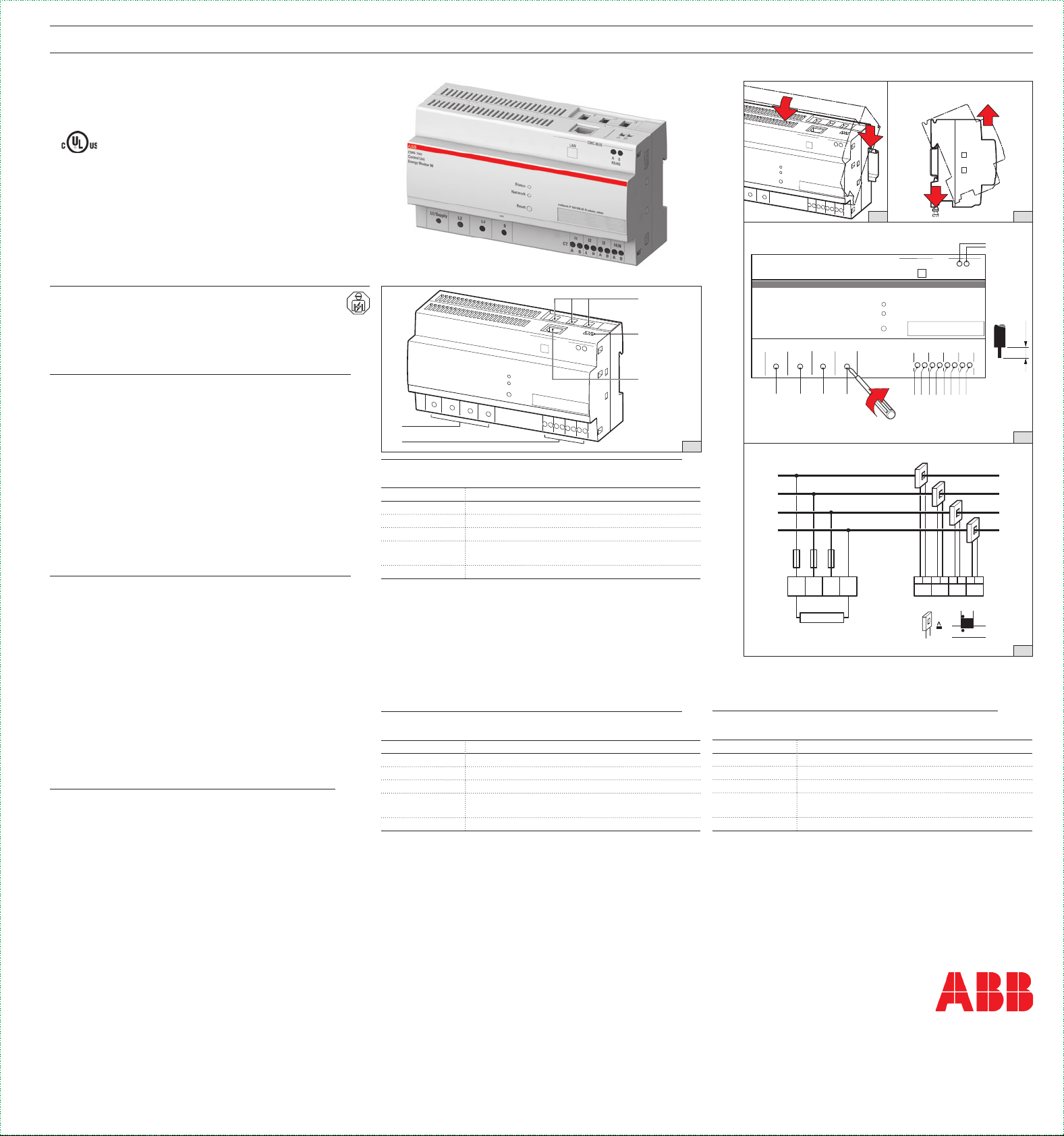
Produktübersicht
Fig. 1
Komponente Beschreibung
1CMS-Bus-Schnittstelle
2RS-485 (2-adrig)
3RJ45-LAN-Anschluss
4Spannungsversorgung L1-N;
Spannungsmessung L1, L2, L3,N
5 Externe Stromwandler L1, L2, L3, L4/N
Montage auf 35mm DIN-Schiene
Fig. 2a
Demontage
Fig. 2b
Anschlussschema
Fig. 3a
Gerät einphasig (L1-N) oder dreiphasig (L1, L2, L3, N) anschliessen
Fig. 3b
Vue d'ensemble du produit F
Fig. 1
Composant Description
1 Interface de bus CMS
2 RS-485 (2 fils)
3Connexion LAN RJ45
4Alimentation électrique L1-N;
mesure de tension L1, L2, L3, N
5 Transformateurs de courant externes L1, L2, L3, L4/N
Montage sur rail DIN 35 mm
Fig. 2a
Démontage
Fig. 2b
Schéma de raccordement
Fig. 3a
Raccorder l'appareil en monophasé (L1-N) ou en triphasé (L1, L2, L3, N)
Fig. 3b
Product overview G
Fig. 1a
Part Description
1CMS-bus Interface
2 RS-485 (2-wire)
3 RJ45 LAN port
4Power supply L1-N;
Voltage measurement L1, L2, L3, N
5 External current transformer L1, L2, L3, L4/N
Assembly on 35mm DIN rail
Fig. 2a
Disconnection
Fig. 2b
Connection diagram
Fig. 3a
Install device single phase (L1-N) or three phase (L1, L2, L3, N)
Fig. 3b
LISTED
IND. CONT. EQ.
E222110
Umgebungstemperatur von maximal 60°C
F Température ambiante maximale de 60°C
Surrounding air temperature rating of 60°C
CMS-700
E245
C
M
S
-700
C
o
ntrol
Unit
Energy Monitor 96
St atus
Ne twor k
Reset
A B
RS485
CMC-BUS
LAN
Fallbac k IP 169.16 8.42 .42; admin, ad min
L1/Supply L 2 L3 N
CT
l1
A B
123
A B
l2
A B
l3
A B
l4/N
A B
L
N
A B
S1 S2
P1 P2
A B
I1
A B
I2
A B
I3
A B
I4/N
L1
L1
L2
L3
N
L2 L3 N
Supply
3b
E245
C
M
S
-700
C
o
ntrol
Unit
Energy Monitor 96
Status
Net work
Reset
A B
RS485
CMC-BUS
LAN
Fallb ack IP 169.168.4 2.42 ;admi n, admin
L1/Supply L2 L 3 N
CT
ABB
l1
A B
l2
A B
l3
A B
l4/N
A B
0.56–0.8 Nm
4 lb-in
0.56–0.8 Nm
4 lb-in
0.56–0.8 Nm
4 lb-in
10 mm
0.39 in
ø
2
E245
Sta tus
Net work
Res et
A B
RS485
CMC-BUS
LAN
Fallback I P 169.168 .42. 42;a dmin, admi n
L3 N
CT
l1
A B
123
A B
l2
A B
l3
A B
l4/ N
A B
2
1
E245
Sta tus
Net work
Res et
A B
RS485
CMC-BUS
LAN
Fallback I P 169.168 .42. 42;a dmin, admi n
L2 L 3 N
CT
l1
A B
123
A B
l2
A B
l3
A B
l4/ N
A B
2
4
3
2b
1
2a
3a


