3
Table of contents
3ADW000803R0101 DCS880 H4T (Tosa) manual en a
Table of contents
DCS880 Drive Manuals..................................................................................................................................................2
Safety instructions 4
What this chapter contains..........................................................................................................................................4
To which products this chapter applies ....................................................................................................................4
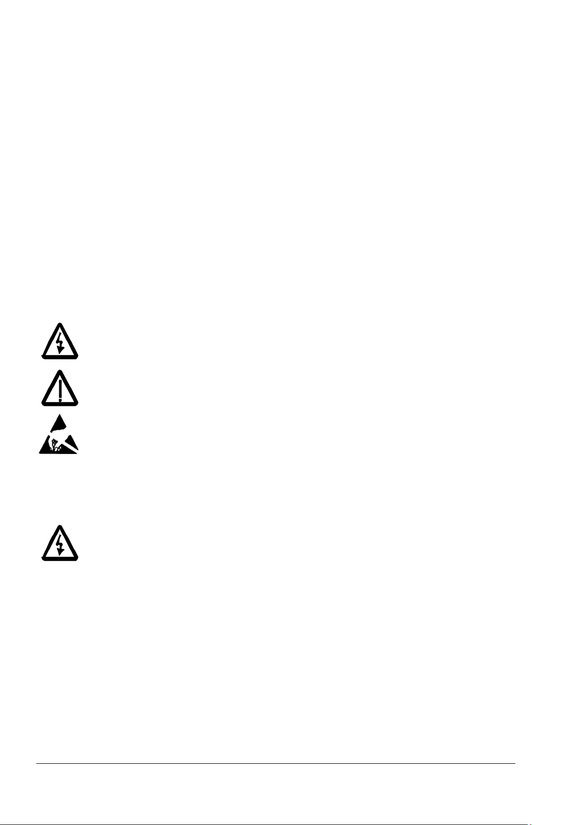
Usage of warnings and notes......................................................................................................................................4
Installation and maintenance work ............................................................................................................................4
Grounding ...................................................................................................................................................................5
Printed circuit boards and fiber optic cables.......................................................................................................5
Mechanical installation .................................................................................................................................................6
Operation.........................................................................................................................................................................6
Introduction to this manual 8
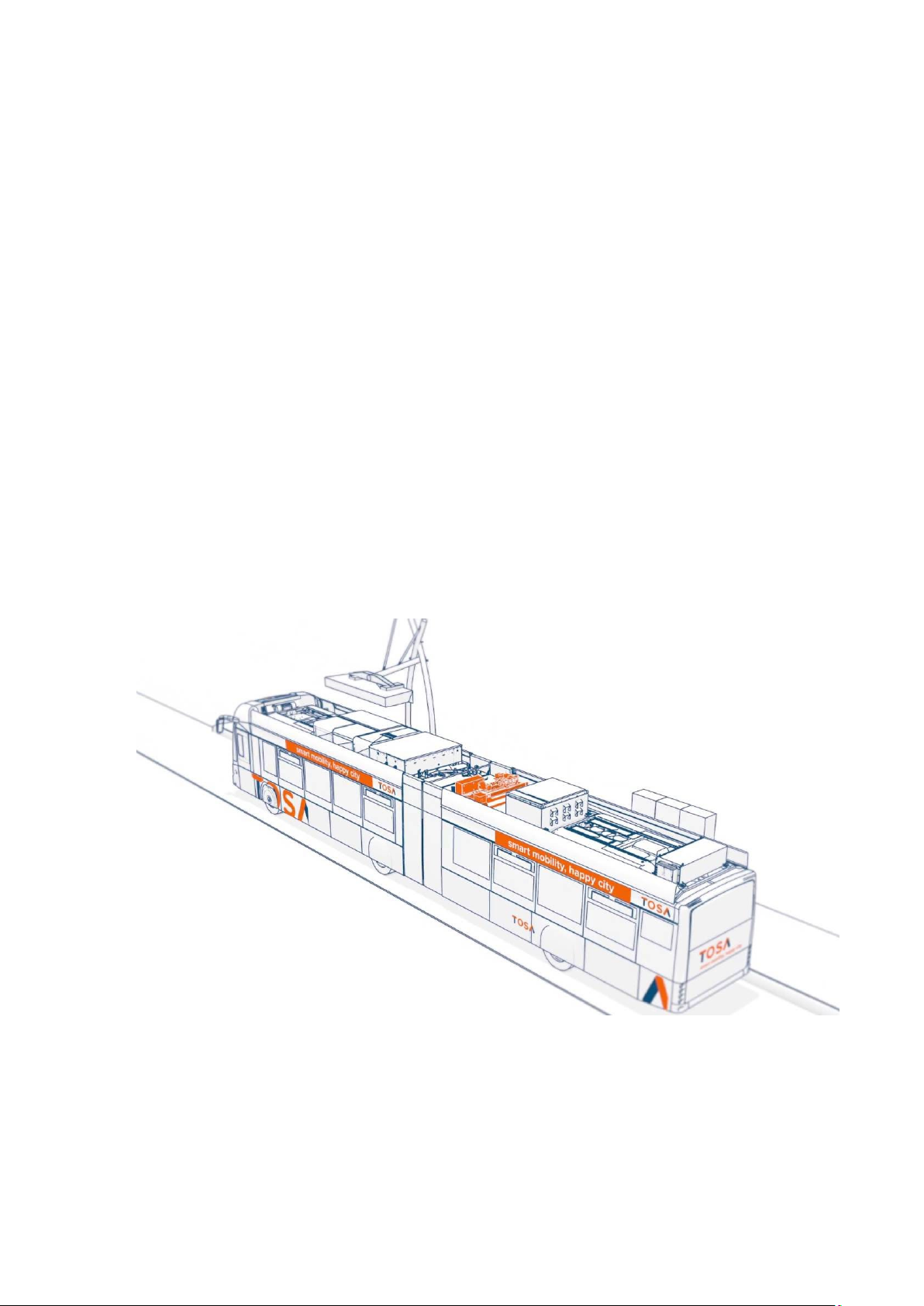
H4T....................................................................................................................................................................................8
Application ......................................................................................................................................................................8
Related documents........................................................................................................................................................8
Terms and abbreviations..............................................................................................................................................9
Cybersecurity disclaimer ............................................................................................................................................ 11
H4T hardware 12
Type code ...................................................................................................................................................................... 12
Type code units size H4T........................................................................................................................................ 13
Main circuit and control..............................................................................................................................................14
Armature converter DCS880 H4T .........................................................................................................................14
Converters size H4T configuration ......................................................................................................................15
Mains power connection ........................................................................................................................................16
Cooling fans ..................................................................................................................................................................16
Fan assignment for DCS880..................................................................................................................................16
Fan cable sizes and tightening torque connected at the fan terminals .......................................................16
Cross-sectional areas - Tightening torques .......................................................................................................16
Current ratings - IEC non regenerative converters (S01)................................................................................. 17
2-Q units size H4T.................................................................................................................................................... 17
Circuit diagram ........................................................................................................................................................18
Galvanic isolation - T90, A92, F11, F90 .................................................................................................................19
Size H4T .................................................................................................................................................................... 20
Fuses and fuse holders IEC for converter size H4T........................................................................................... 21
H4T firmware 22
H4T service 23
Current ratings .............................................................................................................................................................23
Fault Tracing Thyristors 24
Units size H4T...........................................................................................................................................................24
Blown fuses...............................................................................................................................................................24
Exchange thyristors size H4T 25
Remove faulty thyristor modules .........................................................................................................................25
Install new thyristor modules................................................................................................................................32
Commissioning 33