ABB PCS100 ESS User manual

2UCD190000E001 rev. J
PCS100 ESS
Grid Connect Interface for
Energy Storage Systems
User Manual
Introduction
ABB's PCS100 ESS converter is a grid connect interface
for energystorage systems that allows energy to be
stored or accessed exactly when it is required. Able to
connect to any battery type or energy storage medium,
the PCS100 ESS brings together decades of grid inter-
connection experience and leadership in power conver-
sion to provide seamless system integration and battery
control.
The PCS100 ESS’ modular design and advanced control
maximize the availability, value and performance of both
large and small energystorage systems in a variety of
applications. With this optimized use of the energy stor-
age system, the PCS100 ESS helps to deliver exceptional
returns on investment.
The PCS100 ESS allows control of both real power (P)
and reactive power (Q), enabling it to cover a wide range
of system requirements.
Moreover, advanced control features in theVirtual Gener-
ator mode of operation allow this storage system to em-
ulate generator behavior and thus act as a true power
system component.
With these advanced features the PCS100 ESS is the per-
fect solution for applications requiring power system
load levelling, grid stabilization, grid loss detection, grid
compliance for renewable and generation systems and
power quality improvement.
For a comprehensive overview of publications available
for the PCS100 ESS, refer to the inside cover of this pub-
lication. Web links and QR code are also included.

PCS100 ESS User Manual | 2UCD190000E001 rev. J 2
The Company
We are an established world force in the design and man-
ufacture of power electronics and power protection equip-
ment.
As a part of ABB, a world leader in electrical technology,
we offer customers application expertise, service and
support worldwide.
We are committed to teamwork, high quality manufactur-
ing, advanced technology and unrivalled service and sup-
port.
The quality, accuracy and performance of the Company’s
products result from over 100 years of experience, com-
bined with a continuous program of innovative design and
development to incorporate the latest technology.
Quality Control
The products listed in this catalogue are manufactured in
an ISO 9001 accredited facility.
Registration No. 2469
For more information…
Further publications for the PCS100 ESS are available for
free download from https://new.abb.com/power-convert-
ers-inverters/power-converters-and-inverters/pcs100-ess
or by scanning this code:

PCS100 ESS User Manual | 2UCD190000E001 rev. J 3
Overview of this Manual
About this Manual
This manual contains information regarding:
– the general functions of the PCS100 ESS
– the user interface, control and possible adjustments of the PCS100 ESS
– installation and commissioning of the PCS100 ESS
Usage
This manual should be used during operation and adjustment of the PCS100 ESS. It should be referenced when:
– integrating the PCS100 ESS into a complete BESS system
– operating and adjusting the PCS100 ESS
– commissioning the PCS100 ESS
Who should read this manual?
This manual is intended for:
– integrators of the PCS100 ESS
– installation personnel
– operators
Prerequisites
An installation/repair/operator person working with the PCS100 ESS must:
– be trained by ABB and have electrical operational and safety knowledge
– have sufficient training to operate in an accidentally touch safe service environment
Software Revision
This User Manual applies to PCS100 ESS systems with software revision R2M2.
Note: To locate the current software release number, on the GDM’s Control Panel, press Product.
The release number is labeled “Release: …”.

PCS100 ESS User Manual | 2UCD190000E001 rev. J 4
Safety Notices
This manual contains important information regarding the operation of the ABB PCS100 ESS. This manual pro-
vides technical and operational guidance for operators. The following safety instructions are to be observed.
DANGER
This manual does not provide sufficient information for safe service of the PCS100 ESS. For such service infor-
mation refer to appropriate manual.
Please pay due regard to safety as the PCS100 ESSs are high energy devices and require strict precautions to
be taken.
CAUTION – Trained Operators
All operations on the PCS100 ESS must only be carried out by a trained Operator familiar with the contents of
this manual. Hazardous conditions could arise from incorrect adjustment.
Ensure power to the product is isolated and locked off before attempting any work on it.
DANGER – Hazardous Voltages
An Operator must not open doors or panels marked as containing hazardous voltages. Many parts in this prod-
uct, including printed circuit boards operate at lethal voltages. DO NOT TOUCH components or connections that
have voltage present.
DANGER – Stored Charge
Stored charge is present after the device is switched off.
DANGER – Arc Flash
Shorted terminals can cause arc flash resulting in severe burns, severe eye injury or blindness. Use insulated
tools and do not short any terminals.
DANGER – High Leakage Current
The leakage current that is produced during normal operation of an ESS rack system exceeds 3.5 mAac. The
ESS rack system is required to be installed in a fixed connection for protection.
DANGER – Protective Covers
Normal operation of this product requires any protective covers in place and doors secured closed.
DANGER – Personal Protection Equipment
Ensure safety glasses are worn while working if any part of the unit could be energized.
DANGER – Personal Protection Equipment
Ensure appropriate safety footwear is worn if inserting or removing modules or components from the product.

PCS100 ESS User Manual | 2UCD190000E001 rev. J 5
Table of Contents
1Overview.......................................................7
1.1 User Benefits...............................................7
1.2 Features......................................................7
1.3 Applications.................................................7
2Model Definition.............................................8
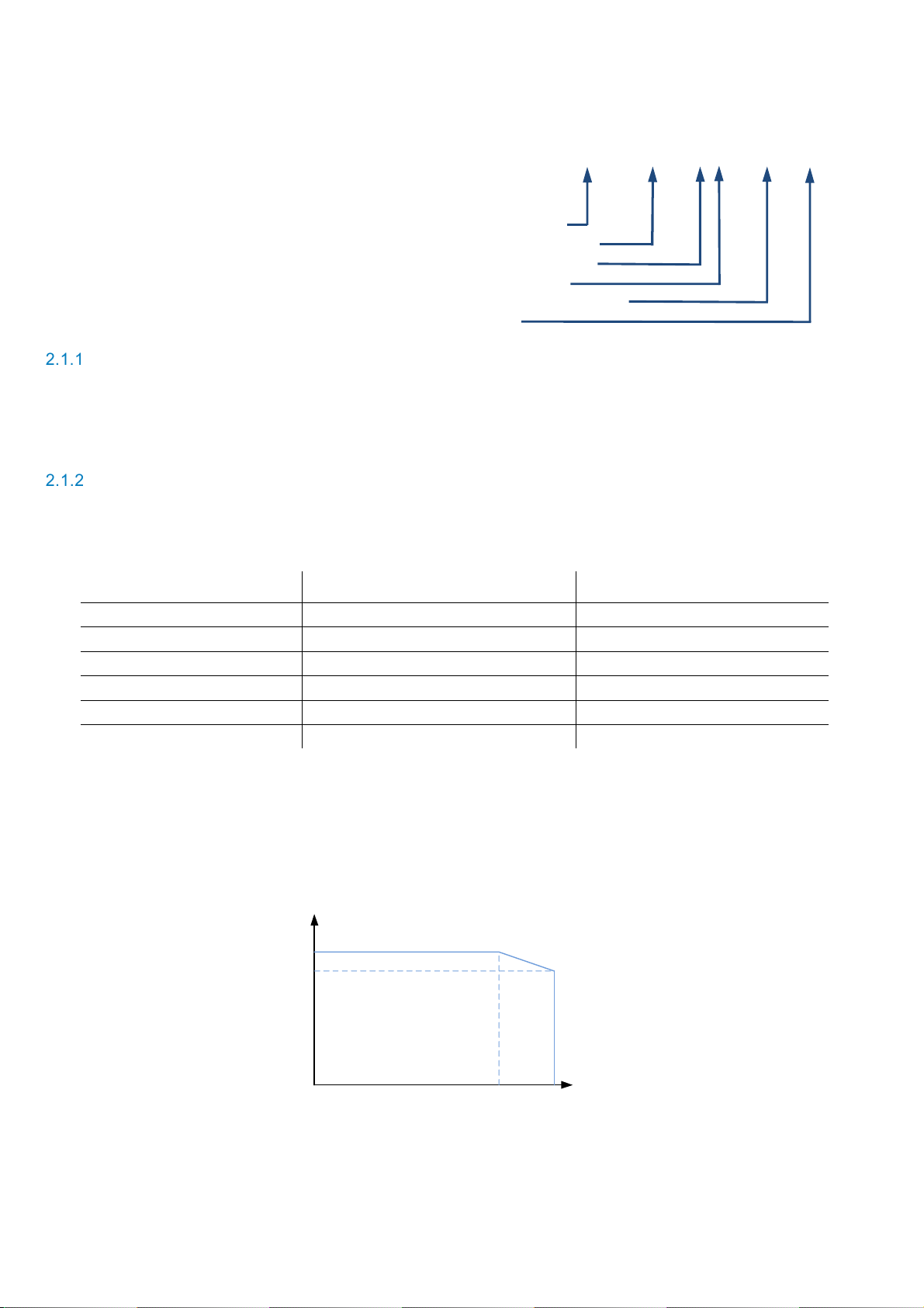
2.1 Type Code ..................................................8
2.1.1 Number of Power Modules ..................... 8
2.1.2 Type of Power Module............................ 8
2.1.3 Mechanical Construction........................ 9
2.1.4 Options.................................................10
2.2 Examples of PCS100 ESS Type Codes.......10
2.3 PCS100 ESS Model Range ........................12
2.3.1 PCS100 ESS D-Type Model Range.......12
2.3.2 PCS100 ESS C-Type Model Range.......13
3Technical Specification ................................14
3.1 Model Range.............................................14
3.2 Utility Side (AC).........................................14
3.3 Energy Storage Side (DC)..........................14
3.4 Standards and Certifications.......................15
3.5 Environmental ...........................................15
3.6 Protection Rating.......................................15
3.7 Service......................................................16
3.8 User Interface............................................16
3.9 Auxiliary Power..........................................16
4Sub-Assemblies...........................................17
4.1 PCS100 ESS Rack and Cabinet..................17
4.2 PCS100 Modules.......................................18
4.3 PCS100 Master Module..............................19
4.3.1 Connections on the Master Module........19
4.3.2 The PCS100 Extended I/O Board..........23
4.4 Metering Interface......................................26
4.4.1 Measurements......................................26
4.4.2 Metering Interface for Cabinet Systems.27
4.4.3 Metering Interface for Rack Systems .....27
4.5 Graphic Display Module (GDM)...................28
5The User Interface.......................................29
5.1 Graphic Display Module (GDM)...................29
5.1.1 Hiding / Showing the Control Button ......29
5.1.2 Navigation Panel...................................30
5.1.3 Status Bar.............................................31
5.1.4 Status Page..........................................32
5.1.5 Event Log Page ....................................34
5.1.6 Product Page........................................35
5.1.7 Menu Page ...........................................36
5.1.8 Starting and Stopping the PCS100 ESS.36
5.1.9 Logging in to the GDM ..........................37
5.2 Module Display Boards...............................38
6Functional Description and Setup.................40
6.1 How it Works............................................. 40
6.2 Virtual Generator Mode (VSI)..................... 40
6.3 Current Source Inverter Mode (CSI)............ 41
6.4 Selecting the System Mode (VSI or CSI)..... 41
6.5 Control Setup in Virtual Generator Mode..... 42
6.5.1 Fixed Power Mode and V/F mode .........43
6.5.2 Frequency and Voltage Droop...............43
6.5.3 Generator Settings ...............................43
6.6 Control Setup in CSI Mode......................... 44
6.7 Inputs and Measurements.......................... 45
6.7.1 Source Selection for Input References..45
6.7.2 DC Voltage Sensing .............................45
6.7.3 Grid Voltage Sensing – VR1 .................46
6.8 Limiting Control Functions.......................... 46
6.8.1 Frequency Envelope.............................47
6.8.2 Voltage Envelope .................................48
6.8.3 SOC Limiter..........................................49
6.8.4 Low Voltage Ride Through (LVRT)........50
6.8.5 Absolute Power Limits..........................51
6.8.6 Customized Power Limits......................51
6.9 Islanding and Anti-Islanding....................... 52
6.9.1 Grid Monitoring.....................................52
6.9.2 Islanding Control Overview...................53
6.9.3 Grid Loss Action...................................56
6.9.4 Re-Synchronization with the Grid..........59
6.10 Using the Converter Loading Feature.......... 59
6.11 Using the Energy Saving Standby Feature.. 59
6.12 Using the Voltage Clamping Feature........... 59
6.13 Using the DC Equalize Feature .................. 60
6.14 DC Voltage Imbalance and Ripple Protection
61
7Protection Requirements.............................. 62
7.1 Input Circuit Protection.............................. 62
7.2 Insulation Monitoring................................. 62
7.3 Arc Fault Hazards and Protection............... 62
7.3.1 Arc Fault and Standards.......................62
7.3.2 Arc Fault Protection Recommendation ..63
7.3.3 Personal protective equipment..............63
8Maintenance................................................64
9Faults, Warnings and other Events...............65
9.1 Resolving a Fault ...................................... 65
9.2 Resolving a Warning ................................. 71
9.3 Events during Normal Operation................. 76
10 Remote Monitoring ......................................77
10.1 List of Ports.............................................. 77
10.2 Cyber Security Information......................... 77
10.2.1 Cyber Security Disclaimer.....................77

1 Overview
PCS100 ESS User Manual | 2UCD190000E001 rev. J 6
10.2.2 List of User/System accounts in ABB
delivery.................................................77
10.3 Displaying the GDM in a Web Browser........ 78
10.4 Downloading the Event Log........................ 78
10.5 Downloading Service Information ............... 79
11 Commissioning ............................................80
11.1 Pre-Power Visual Checks........................... 80
11.2 Power Connection Checks......................... 81
11.3 Isolation transformer check list................... 81
11.4 Earth (Ground) Checks.............................. 81
11.5 Initial Power Up (Low Power)..................... 82
11.6 Initial Power Up (Utility Power)................... 82
11.7 Initial Run (No Load) ................................. 83
11.8 Load Test ................................................. 83
11.9 Documentation and Handover.................... 83
11.10Parameters change record......................... 84
12 Appendices..................................................85
Appendix A – GDM Menu Reference................... 86
GDM Parameter Index.....................................86
GDM Parameter ..............................................94
Appendix B – MODBUS Parameters & Error Codes
.............................................................. 130
MODBUS TCP Supported Functions..............130
MODBUS RTU RS-485 Supported Functions..130
General Status and Measurements Registers.131
Configuration Parameters.............................. 136
Control Parameters....................................... 139
Setpoint Status ............................................. 141
CAN IO Board Status.................................... 142
Power Module Internal Temperatures............ 144
Rack Module Internal Temperatures.............. 146
Frequency and Voltage Envelopes’ Parameters
147
Grouped Parameters..................................... 148
Modbus Error Codes..................................... 149
Detailed Product Status Codes...................... 150
Appendix C – Open Source Software.................151
Appendix D – Wiring Information........................151
Maximum CAN Bus Length............................ 151
Analog AR1 and AR2 Inputs.......................... 151
Appendix E - Torque settings and Bolt order.......152
Appendix F – Installation requirements...............152
Floor Requirements....................................... 152
Location........................................................ 152
Dedicated Transformer.................................. 152
Appendix G – General Disclaimer......................152
Appendix H – Waste Electrical and Electronic
Equipment Information (WEEE) ................152
Appendix I – Glossary.......................................153
13 List of Related Documentation....................154

1 Overview
PCS100 ESS User Manual | 2UCD190000E001 rev. J 7
1 Overview
In today’s power systems energy storage devices such as new generation batteries, flywheels and super capacitors provide
the opportunity to store energy from the electricity grid and return it when required. This offers a huge range of options to
strengthen and enhance the performance, quality and reliability of smart electricity grids. Providing the grid connect inter-
face for all types of energy storage devices, the PCS100 ESS is the perfect solution to connect such energy storage devices
to the grid.
The PCS100 ESS is based on a LV converter platform especially developed for power quality issues and characterized by
wide bandwidth performance and great flexibility thanks to its modular power electronic configuration. It offers two main
modes of operation, namely Current Source mode and Virtual Generator mode, which enables the PCS100 ESS to cover a
wide range of applications and power system requirements. Both modes offer independent control of both real power (P)
and reactive power (Q) providing the highest possible flexibility to the operator. In addition, advanced control features in the
Virtual Generator mode allow the PCS100 ESS to emulate generator behavior and thus to interact with the power system in
the same way as a traditional synchronous machine. Such behavior is achieved purely through power electronic control and
there are no large spinning masses.
In case the grid supply is lost the system can be set to shut down according to anti-islanding standards or to operate in is-
land mode, where the PCS100 ESS operates disconnected from the main grid but continues to supply local loads. When
operating in island mode, the PCS100 ESS can automatically re-synchronize the islanded network with the main grid, allow-
ing a seamless transfer back to grid connect mode.
1.1 User Benefits
– Supports power system load levelling and thus helps defer network and generation investment
– Increases network stability and transmission capacity and thus facilitates increased use of renewables
– Delivers grid compliance for renewable and other generation systems
– Damps disturbances and oscillations in critical system configurations
– Modular design for highest availability
– Based on LV converter platform especially developed for power quality issues
1.2 Features
– Modular design providing high reliability and typically 30 minutes mean time to repair (MTTR)
– Grid fault detection
– Islanding and anti-islanding options
– Ratings from 100 kVA to 4000 kVA and voltages from 150 Vac to 480 Vac
– Allows a range of energy storage devices to be coupled to the grid
– Dynamic real power control (P)
– Dynamic reactive power control (Q)
– Generator emulating control mode
– Grid stabilization features including synthetic inertia and active damping
– Low voltage ride through (LVRT)
– Voltage and frequency dynamic envelope/regulation functions
– Voltage clamping for reactive power grid support
– Black start option
1.3 Applications
– Integration of renewable energy (to meet grid codes regarding LVRT, ZVRT)
– Load levelling for optimized generation utilization
– Spinning reserve in case of line loss
– Frequency regulation
– Peak shaving (end user)
– Micro grids, Islanding and Anti-Islanding

2 Model Definition
PCS100 ESS User Manual | 2UCD190000E001 rev. J 8
2 Model Definition
2.1 Type Code
The PCS100 ESS type code is given in the product ta-
bles. The type code is a unique code for the specific
PCS100 ESS model and specifies all the components
that are used to construct the model. To the type code
given in the product tables options can be added,
which are called plus (+) codes.
The diagram on the right outlines the structure of the
type code:
PCS100 19 - 14D - B21+…
Product Series
PCS100 ESS Code
Number of Modules
Type of Module
Mechanical Construction
Options
Number of Power Modules
This is the number of modules used in the PCS100 ESS system, which depends on the load kVA.
One PCS100 ESS cabinet can have up to 6 PCS100 power modules and one PCS100 ESS rack converter up to 32 mod-
ules. In case a bigger system is required multiple PCS100 ESS can be connected in parallel. In this case, the units must be
tied together with separate transformers or multi-winding transformers.
Type of Power Module
There are two types of power modules available for the PCS100 ESS, which differ in their DC voltage range. The D-type
module is suitable for DC voltages up to 820 Vdc. For higher DC voltages the C-type module has to be used, which can run
up to 1120 Vdc.
Parameters D-Type Module C-Type Module
Rated DC voltage1750Vdc (250 – 820 Vdc) 1000Vdc (250 – 1120 Vdc)
Rated AC voltage2480 Vac (150 – 480 Vac) 480 Vac (150 – 480 Vac)
Current at rated AC voltage 150 Aac 105 Aac
Nominal frequency 50/60 Hz 50/60 Hz
DC side grounding DC side RFI grounded DC side RFI grounded
AC side grounding Floating (AC transformer coupled) Floating (AC transformer coupled)
Note: 1Power derating is required for continuous operation above 780 Vdc and 1065 Vdc as illustrated in Figure 2-1.
2This is the standard rated AC voltage. Other operating voltages (as indicated in brackets) can be achieved based
on sizing criteria and software settings. The product will be delivered set up for the voltage specified in the sizing
tool.
Figure 2-1: Derating curve for continuous operation at high DC voltages
Load
Vdc
100%
80%
D-820V
C-1100V
D-780V
C-1065V

2 Model Definition
PCS100 ESS User Manual | 2UCD190000E001 rev. J 9
Mechanical Construction
This specifies the type of mechanical construction, with A10 denoting the standard cabinet and Bxx the standard rack. For
some cases the letter Cxx1will be used, denoting a specific application or duty cycles.
8-Modules rack section 16-Modules rack section Cabinet
A10 - Standard cabinet solution (800W x 800D)
Bxx - Standard rack solution
Bxx - Number of 8-modules sections:
B1 = 8-modules rack
B2 = 16-modules rack
B3 = 16-modules + 8-modules racks
B4 = 16-modules + 16-modules racks
C2 = 16-modules rack1
C3 = 16-modules + 8-modules racks1
C4 = 16-modules + 16-modules racks1
Bxx– Busbar requirements: 1= AC/DC left - (up to 16 modules)
2= AC/DC right - (up to 16 modules)
3= AC left, DC right - (up to 16 modules)
4= AC right, DC left - (up to 16 modules)
C= Center fed 16-modules rack RH side (16 < modules < 25)2
D= Center fed 16-modules rack LH side (16 < modules < 25)
Overview modules and racks:
Cabinets Rack with D-Type Modules Rack with C-Type Modules
A10 1-6 modules
B1x 1-8 modules
B2x 9-14 modules
C2x 15-16 modules1
B3x 15-22 modules
C3x 23-24 modules1
B4x 25-28 modules
C4x 29-32 modules1
B1x 1-8 modules
B2x 9-16 modules
B3x 17-24 modules
B4x 25-32 modules
Note: 1For racks with D-type modules typically a maximum of 14 modules can be placed into one rack (two sections of 8
modules) due to current limitations on the DC bus. Contact factory in case you require more than 14 modules on a
single rack (two sections of 8 modules) for specific applications with continuous DC currents below 2500 Adc, or
specific duty-cycles applications.
2For racks over 24 modules, two sections of 16-modules are required. Therefore, there is not distinction where it is
located. By default, the code for busbar requirement will be C

2 Model Definition
PCS100 ESS User Manual | 2UCD190000E001 rev. J 10
Options
This specifies the different options available for the PCS100 ESS either cabinet or rack solution. Any other configuration not
specified in this document will be denoted with a +C.
+T000 = Tx ready (1 and 2 modules cabinet only)
+C = Customized solution (contact factory)
VR1 Remote synch input:+480x3 = 480 V, 3 wire
+480x4 = 480 V, 4 wire
+110x4 = 110 V, 4 wire
+110x3 = 110 V, 3 wire
2.2 Examples of PCS100 ESS Type Codes
PCS100 19-01D-A10 … PCS100 19-06D-A10 PCS100 19-01C-A10+T000
PCS100 19-01C-A10 PCS100 19-03D-A10

2 Model Definition
PCS100 ESS User Manual | 2UCD190000E001 rev. J 11
PCS100 19-08D-B11 PCS100 19-16C-B22
PCS100 19-24C-B3C PCS100 19-22C-B3D
Further information about rack’s components con-
nection can be found in the PCS100 ESS Wiring Di-
agram, 2UCD190xxxE301.
Any other configuration not specified in this docu-
ment will be a customized solution (contact factory)
PCS100 19
-
32C
-
B
4
C

2 Model Definition
PCS100 ESS User Manual | 2UCD190000E001 rev. J 12
2.3 PCS100 ESS Model Range
The model ratings of the PCS100 ESS are defined by the number of power modules used to construct the system. The
PCS100 ESS product range is summarized in section 2.3.1 for D-type modules and in section 2.3.2 for C-type modules.
The ratings are given for a typical PCS100 ESS system under nominal conditions.
Note: Operation at different voltages than nominal will affect the power rating. Consult 2UCD190000E025 PCS100 ESS
Detailed Sizing Tool for the exact rating according to your operating conditions.
PCS100 ESS D-Type Model Range
Number of Mod-
ules
Dimensions
H x W x D (mm)
Weight
kg
Rated Current
Iac (A)
Heat dissipation
kW (Typical)
Airflow
(m3/min)
Type Code
12154x809x804 790 150 4.9114 PCS100 19-01D-A10+T0002
22154x809x804 920 300 8.8124 PCS100 19-02D-A10+T0002
12154x809x804 330 150 2.9 10 PCS100 19-01D-A10
22154x809x804 410 300 5.8 20 PCS100 19-02D-A10
32154x809x804 490 450 8.7 30 PCS100 19-03D-A10
42154x809x804 570 600 11.6 40 PCS100 19-04D-A10
52154x809x804 650 750 14.4 50 PCS100 19-05D-A10
62154x809x804 730 900 17.3 60 PCS100 19-06D-A10
42200x1041x703 560 600 11.5 40 PCS100 19-04D-B1x3
52200x1041x703 630 750 14.4 50 PCS100 19-05D-B1x3
62200x1041x703 700 900 17.3 60 PCS100 19-06D-B1x3
72200x1041x703 770 1050 20.1 70 PCS100 19-07D-B1x3
82200x1041x703 840 1200 23.0 80 PCS100 19-08D-B1x3
92200x2041x703 1020 1350 25.9 90 PCS100 19-09D-B2x3
10 2200x2041x703 1080 1500 28.8 100 PCS100 19-10D-B2x3
11 2200x2041x703 1150 1650 31.6 110 PCS100 19-11D-B2x3
12 2200x2041x703 1220 1800 34.5 120 PCS100 19-12D-B2x3
13 2200x2041x703 1300 1950 37.4 130 PCS100 19-13D-B2x3
14 2200x2041x703 1370 2100 40.3 140 PCS100 19-14D-B2x3
15 2200x(1041+2041)x703 1710 2250 43.1 150 PCS100 19-15D-C52x3
16 2200x(1041+2041)x703 1780 2400 46.0 160 PCS100 19-16D-C52x3
17 2200x(1041+2041)x703 1850 2550 48.9 170 PCS100 19-17D-B3x4
18 2200x(1041+2041)x703 1920 2700 51.8 180 PCS100 19-18D-B3x4
19 2200x(1041+2041)x703 1990 2850 54.6 190 PCS100 19-19D-B3x4
20 2200x(1041+2041)x703 2070 3000 57.5 200 PCS100 19-20D-B3x4
21 2200x(1041+2041)x703 2140 3150 60.4 210 PCS100 19-21D-B3x4
22 2200x(1041+2041)x703 2210 3300 63.3 220 PCS100 19-22D-B3x4
23 2200x(2041+2041)x703 2280 3450 66.1 230 PCS100 19-23D-C53x4
24 2200x(2041+2041)x703 2350 3600 69.0 240 PCS100 19-24D-C53x4
25 2200x(2041+2041)x703 2520 3750 71.9 250 PCS100 19-25D-B4C
26 2200x(2041+2041)x703 2590 3900 74.8 260 PCS100 19-26D-B4C
27 2200x(2041+2041)x703 2660 4050 77.6 270 PCS100 19-27D-B4C
28 2200x(2041+2041)x703 2730 4200 80.5 280 PCS100 19-28D-B4C
29 2200x(2041+2041)x703 2800 4350 83.4 290 PCS100 19-29D-C54C
30 2200x(2041+2041)x703 2870 4500 86.3 300 PCS100 19-30D-C54C
31 2200x(2041+2041)x703 2940 4650 89.1 310 PCS100 19-31D-C54C
32 2200x(2041+2041)x703 3010 4800 92.0 320 PCS100 19-32D-C54C
Note: 1Assuming typical additional heating from coupling transformer.
2T000 option with free space for customer coupling transformer inside the cabinet (does not include transformer).
3Refer to section 2.1.3 for the right code according the bus bars termination
4Place C for center termination (2 m rack on the right) or D for center termination (2 m rack on the left)
5Please consult factory for any systems with over 14 D-type modules on a single two-section rack. Refer to 2.1.3

2 Model Definition
PCS100 ESS User Manual | 2UCD190000E001 rev. J 13
PCS100 ESS C-Type Model Range
Note: 1Assuming typical additional heating from coupling transformer.
2T000 option with free space for customer coupling transformer inside the cabinet (does not include transformer).
3Refer to section 2.1.3 for the right code according the bus bars termination
4Place C for center termination (2 m rack on the right) or D for center termination (2 m rack on the left)
Number of Mod-
ules
Dimensions
H x W x D (mm)
Weight (approx.)
kg
Rated Current
Iac (A)
Heat dissipation
kW (Typical)
Airflow
(m3/min)
Type Code
12154x809x804 780 105 4.4114 PCS100 19-01C-A10+T0002
22154x809x804 900 210 7.7124 PCS100 19-02C-A10+T0002
12154x809x804 330 105 2.4 10 PCS100 19-01C-A10
22154x809x804 410 210 4.7 20 PCS100 19-02C-A10
32154x809x804 490 315 7.1 30 PCS100 19-03C-A10
42154x809x804 570 420 9.4 40 PCS100 19-04C-A10
52154x809x804 650 525 11.8 50 PCS100 19-05C-A10
62154x809x804 730 630 14.1 60 PCS100 19-06C-A10
42200x1041x703 560 420 9.4 40 PCS100 19-04C-B1x3
52200x1041x703 630 525 11.8 50 PCS100 19-05C-B1x3
62200x1041x703 700 630 14.1 60 PCS100 19-06C-B1x3
72200x1041x703 770 735 16.5 70 PCS100 19-07C-B1x3
82200x1041x703 840 840 18.8 80 PCS100 19-08C-B1x3
92200x2041x703 1020 945 21.2 90 PCS100 19-09C-B2x3
10 2200x2041x703 1080 1050 23.5 100 PCS100 19-10C-B2x3
11 2200x2041x703 1150 1155 25.9 110 PCS100 19-11C-B2x3
12 2200x2041x703 1220 1260 28.2 120 PCS100 19-12C-B2x3
13 2200x2041x703 1300 1365 30.6 130 PCS100 19-13C-B2x3
14 2200x2041x703 1370 1470 32.9 140 PCS100 19-14C-B2x3
15 2200x2041x703 1440 1575 35.3 150 PCS100 19-15C-B2x3
16 2200x2041x703 1510 1680 37.6 160 PCS100 19-16C-B2x3
17 2200x(1041+2041)x703 1850 1785 40.0 170 PCS100 19-17C-B3x4
18 2200x(1041+2041)x703 1920 1890 42.3 180 PCS100 19-18C-B3x4
19 2200x(1041+2041)x703 1990 1995 44.7 190 PCS100 19-19C-B3x4
20 2200x(1041+2041)x703 2070 2100 47.0 200 PCS100 19-20C-B3x4
21 2200x(1041+2041)x703 2140 2205 49.4 210 PCS100 19-21C-B3x4
22 2200x(1041+2041)x703 2210 2310 51.7 220 PCS100 19-22C-B3x4
23 2200x(1041+2041)x703 2280 2415 54.1 230 PCS100 19-23C-B3x4
24 2200x(1041+2041)x703 2350 2520 56.4 240 PCS100 19-24C-B3x4
25 2200x(2041+2041)x703 2520 2625 58.8 250 PCS100 19-25C-B4C
26 2200x(2041+2041)x703 2590 2730 61.1 260 PCS100 19-26C-B4C
27 2200x(2041+2041)x703 2660 2835 63.5 270 PCS100 19-27C-B4C
28 2200x(2041+2041)x703 2730 2940 65.8 280 PCS100 19-28C-B4C
29 2200x(2041+2041)x703 2800 3045 68.2 290 PCS100 19-29C-B4C
30 2200x(2041+2041)x703 2870 3150 70.5 300 PCS100 19-30C-B4C
31 2200x(2041+2041)x703 2950 3255 72.9 310 PCS100 19-31C-B4C
32 2200x(2041+2041)x703 3020 3360 75.2 320 PCS100 19-32C-B4C

3 Technical Specification
PCS100 ESS User Manual | 2UCD190000E001 rev. J 14
3 Technical Specification
3.1 Model Range
AC Rating
150A – 4800A D-type module
105A – 3360A C-type module
Note: Higher power available by paralleling multiple
PCS100 ESS systems.
3.2 Utility Side (AC)
Rated voltage 150 - 480 V
Voltage tolerance ± 10 %
Nominal frequency 50 Hz or 60 Hz
Frequency tolerance ± 5 %
Power system
3-phase center ground referenced (TN-S) - coupling transformer re-
quired1.
3-phase floating system (IT) - insulation monitoring required2.
Note: 1For transformer requirements refer to
ABB document 2UCD190000E006 ESS Transformer
. Requirements.
2For more information refers to section 7.2 in this manual.
Overvoltage category III – 4kV (IEC 60664)
Fault capacity 25 kA (cabinet), 65 kA (rack)
Achievable efficiency 98 %
Overload capability 200 % for 2 seconds1
150 % for 30 seconds
120 % for 600 seconds1
Note: 1From 75% preload, refer to document
2UCD190000E013 PCS100 ESS Overload.
Circuit protection Circuit breaker or fuse (not included)
Voltage harmonic compatibility IEC 61000-2-4 Class 2 (Utility THDv < 8%)
Note: For THDv > 8%, please refer to factory.
For applications where THDv is above 10% lifetime of com-
ponents may be significantly affected, please refer to factory.
Power module voltage harmonic
distortion THDv < 2.5% for linear loads
3.3 Energy Storage Side (DC)
Rated voltage +/- 125Vdc up to +/- 560Vdc (250 up to 1120 Vdc) for C-type
+/- 125Vdc up to +/- 410Vdc (250 up to 820 Vdc) for D-type
Supply earth referencing DC center referenced
Overvoltage category II (IEC 60664)
4kV D-type module
6kV C-type module
Note: The PCS100 ESS system is rated for use in systems which
will not be subject to impulse voltages exceeding their over-
voltage rating. Suitably rated surge protection devices (SPDs)
should be connected from + and - to earth in applications
where surge voltage may exceed the overvoltage
rating (e.g.: remote connected DC sources).

3 Technical Specification
PCS100 ESS User Manual | 2UCD190000E001 rev. J 15
Maximum, voltage to ground +/- 600Vdc
Note: The PCS100 ESS system is in systems which
will not be subject to impulse voltages exceeding their over-
voltage rating. Suitably rated surge protection devices (SPDs)
should be connected from + and - to earth in applications
where surge voltage may exceed the overvoltage
rating (e.g.: remote connected DC sources).
Circuit protection Circuit breaker or fuse (not included)
3.4 Standards and Certifications
Quality ISO 9001
Marking
Refer to 2UCD200000E801 for UL recognized PCS100 components.
Safety IEC 62103
Electromagnetic compatibility
Emissions CISPR 11 Class A Group 1
Immunity IEC 61000-6-2
Note: Minimum requirements must be met to achieve the
EMC claimed performance at the ESS demarcation point. For-
More information please refer to ABB document.
2UCD190000E006 ESS Transformer Requirements
Performance (Aligned with) IEEE 519
IEEE 1031-2000
Grid connection/monitoring
(Aligned with) IEEE 1547
Japanese Grid Code
3.5 Environmental
Operating temperature range 0 °C to 50 °C
Temperature derating Above 40 °C, derate at 2 % load per °C
Operating altitude < 1000 m without derating
Capacity derating with altitude 1 % every 100 m above 1000 m, 2000 m maximum
Inverter cooling forced ventilation
Humidity < 95 %, non-condensing
Pollution degree rating 2
Noise < 85 dBA @ 2 m
Note: Average from measurements taken all around of a 32 type-
C
. modules rack @ fully loaded.
Seismic rating Designed to UBC zone 4 (rack only)
3.6 Protection Rating
Rack / Cabinet rating IP20 / NEMA 1
Note: On Rack systems, the IP rating is characterized by the
inverter modules only. Final protection degree dependent on
application.

3 Technical Specification
PCS100 ESS User Manual | 2UCD190000E001 rev. J 16
3.7 Service
MTTR 30 min typical by module exchange
Diagnostics Non-volatile event & service log
3.8 User Interface
User interface 8.4” color touch panel
Touch panel Full parameter control, system event log
Control inputs 10 digital inputs 24 Vdc (< 50ms)
- Start / Stop / Reset (Master Module)
- 7 programmable inputs
2 analog inputs on the extended I/O board
-10…+10 V / 4…20 mA, (< 2ms)
Resolution 0.1 %, Accuracy ± 2 %
2 PTC inputs
Control outputs 7 digital relay outputs, 250 V/1~, 30 Vdc (1 A)
- Running, warning, fault relays (Master Module)
- 4 programmable outputs on the extended I/O board
2 analog outputs on the extended I/O board
-10…+10 V / 4…20 mA (< 50ms)
Accuracy ± 2 %
Communication Ethernet
Modbus TCP/IP
RS485, Modbus RTU
3.9 Auxiliary Power
In case of rack systems two types of auxiliary power have to be provided from an external source1:
-26.5 Vdc safety extra low voltage dc for control
-230 Vac 50/60 Hz fan supply
It must be ensured that these external power supplies are suitable for industrial use and that cables are dimensioned appro-
priately. Attention should also be given to the grounding of the supplies: The 0Vdc of the 26.5 Vdc supply must be tied to
ground at one point and the 230 Vac fan supply should be configured as a TN (hard grounded) supply. Furthermore, it is not
recommended to connect other loads to the 26.5 Vdc supply or to interconnect +26.5 Vdc or 0 V lines when multiple sup-
plies are used in larger systems.
More detailed information about the dimensioning of the auxiliary supplies can be found in the application note
2UCD000420E003 “Auxiliary Power Supplies for PCS100 Rack Systems”.
Note: 1In case of cabinet systems the control auxiliary power is provided by an internal 26.5 Vdc power supply located in
the Auxiliary Master Module and the only external supply is the 110 or 230 Vac 50/60 Hz as described in this sec-
tion. It is worth noting that on cabinet versions the Auxiliary Master Module is 230Vac 50/60Hz, but is always sup-
plied by an auxiliary “Z” transformer which allows customers to provide power either on 110Vac or 230Vac de-
pending on the connection of the primary windings of such auxiliary transformer.

4 Sub-Assemblies
PCS100 ESS User Manual | 2UCD190000E001 rev. J 17
4 Sub-Assemblies
The PCS100 ESS consists of the following parts:
– PCS100 Rack or Cabinet
– PCS100 Module
– PCS100 Master Module
– PCS100 Metering Interface
– PCS100 GDM Display
Together these sub-assemblies are referred to as the PCS100 ESS System.
4.1 PCS100 ESS Rack and Cabinet
The PCS100 ESS system contains an appropriate number of PCS100 modules for the rating of the product. Each
module has a unique identification number (1 - 32), which is displayed on the front of the module as shown in
more detail in section 5.2.
Depending on the requirements of an application, the modules can be placed either in a rack or in a cabinet. If
cabinet construction is selected, all parts will be delivered fully assembled in a cabinet. To be ready for use only
the cabinets need to be connected in parallel in case more than one cabinet is needed for the application. On the
other hand, if rack construction is selected, the certain parts are shipped separately and will have to be assem-
bled into the rack system before the PCS100 ESS system can be used.
As shown in more detail in section Error! Reference source not found., the maximum number of modules varies
between rack and cabinet systems: A single cabinet can contain up to 6 modules. In case of one or two modules
a transformer can also be included in the cabinet enclosure as detailed in the product range in section 2.3. A sin-
gle rack can contain up to two rack sections of 1000 mm, giving a maximum of 16 modules (max. 8 modules per
rack section). For PCS100 ESS systems requiring more than 16 modules, two racks can be connected with a cen-
ter termination as explained in more detail in section Error! Reference source not found..
Figure 4-1: PCS100 ESS Rack
DANGER – Hazardous Voltages
Many parts in this product, including printed circuit boards operate at lethal voltages.
DO NOT TOUCH components or connections that have voltage present

4 Sub-Assemblies
PCS100 ESS User Manual | 2UCD190000E001 rev. J 18
4.2 PCS100 Modules
The PCS100 modules are the link between the energy storage and the main grid. They present a regulated three
phase AC voltage (in Virtual Generator VSI mode) or a regulated three phase AC current (in CSI mode) to the grid
and transfer power from the grid to the energy storage and vice versa.
As shown in Figure 4-2, the PCS100 modules include a sine filter and a RFI filter as part of the assembly, mean-
ing the power electronics and filters are integrated into one module. Thanks to this and the use of state of the art
IGBT technology the PCS100 modules have minimum impact on power quality of the supply network (harmonics
and power factor). They are delivered in the compact package shown in Figure 4-3.
Figure 4-2: Diagram of a PCS100 module
Figure 4-3: PCS100 Power Module

4 Sub-Assemblies
PCS100 ESS User Manual | 2UCD190000E001 rev. J 19
4.3 PCS100 Master Module
Each PCS100 ESS system has one Master Module that controls the over-
all system operation from a central point by coordinating the function of all
PCS100 modules.
The Master Module controls the operating state of the overall system and
combines the measurements and feedback from all the PCS100 modules
into a single data set. It also identifies significant events in the system
(e.g. a fault state of a module) and stores them in an event log. Further-
more, it performs the system-wide input voltage sensing and calculates
the reference values for the PCS100 modules based on the system-wide
reference values set by the operator.
In case of cabinet systems, the Master Module is called the Auxiliary Mas-
ter Module and includes an internal 26.5 Vdc power supply and a 600ms
hold-up circuit in case of AC supply failure. The master module is fed via a
230V 50/60Hz Supply. In addition, the power for the fan supply (230Vac)
also is provided from an external source.
In case of rack systems, the Master Module is referred to as PCS100
Compact Master Module and does not contain an internal power supply.
Figure 4-4 shows a Compact Master Module.
Figure 4-4: PCS100 Compact
Master Module
Connections on the Master Module
The PCS100 ESS includes several control and control power connections for local and remote control and moni-
toring of the system. All terminals are located on the PCS100 Master Module and are suitable for wires up to 2.5
mm2cross section.
The following sections describe these connections in more detail. It includes some information on cabinet sys-
tems, however, the main focus is on rack systems as they still have to be assembled during installation.
4.3.1.1 Digital I/Os and Power Terminals
On the PCS100 Compact Master Module (rack systems) shown in Figure 4-5 there are digital input and output
terminals to activate remote control and monitor the status of the system, as well as power terminals to supply the
compact master from an external 26.5Vdc source.1The numbering of these terminals is shown in Figure 4-6 to-
gether with a short description in Table 4-1. In comparison the Auxiliary Master Module used in cabinet systems is
shown in Figure 4-7.
Figure 4-5: PCS100 Compact Master Module
Note: 1In case of cabinet systems the master module is fed from an internal 26.5Vdc power supply.

4 Sub-Assemblies
PCS100 ESS User Manual | 2UCD190000E001 rev. J 20
1NC
2 C
3NO
4
5
6
7
8
9
10
11
12
13
14
15
NC
C
NO
NC
C
NO
0 V
RUN
250 Vac / 30 Vdc
1 A
WARNING
250 Vac / 30 Vdc
1 A
FAULT
250 Vac / 30 Vdc
1 A
START
0 V
STOP / INHIBIT / RESET
1
2
3
4
5
6
7
8
9
10
11
12
13
14
15
16
- +
Customer Monitoring
and Alarm Systems
Remote Control
16
17 17
1818 1919
20 20
2121
22 22
2323 2424
25 25
2626
27 27
2828 PSU OUT -
+
+
+
-
-
-
+
-
PSU OUT +
PSU 2 -
PSU 2 +
PSU 1 -
PSU 1 +
PTC
PTC
Control
Power
Figure 4-6: Remote Control, Monitoring and Control Power Terminals on the PCS100 Compact Master Module
Terminal
Number
Description Name
1Relay output / 250 Vac/30 Vdc, 1 A / NC RUN Status (Normally Closed)
2Relay output / 250 Vac/30 Vdc , 1 A / C RUN Status (Common)
3Relay output / 250 Vac/30 Vdc , 1 A / NO RUN Status (Normally Open)
4Relay output / 250 Vac/30 Vdc , 1 A / NC WARNING Status (Normally Closed)
5Relay output / 250 Vac/30 Vdc , 1 A / C WARNING Status (Common)
6Relay output / 250 Vac/30 Vdc , 1 A / NO WARNING Status (Normally Open)
7Relay output / 250 Vac/30 Vdc , 1 A / NC FAULT Status (Normally Closed)
8Relay output / 250 Vac/30 Vdc , 1 A / C FAULT Status (Common)
9Relay output / 250 Vac/30 Vdc , 1 A / NO FAULT Status (Normally Open)
10 NA 10
11 NA 11
12 Dry contact only: Return Wire 0V Start Input – return
13 Dry contact only: Start on closing edge START Start Input – only used if remote Start
is required
14 Dry contact only: Return Wire 0V Stop/Inhibit/Reset - return
15 Dry contact only: Stop on open edge: Inhibit while
open; Reset on open edge Stop/Inhibit/Reset – input
16 NA 16
17 NA 17
18 NA 18
19 NA 19
20 NA 20
21 PTC input (e.g. for transformer supervision) PTC
22 PTC input (e.g. for transformer supervision) PTC
This manual suits for next models
5
Table of contents
Other ABB Recording Equipment manuals