ABB FEN-31 User manual

—
OPTIONS FOR ABB DRIVES AND CONVERTERS
HTL Encoder Interface FEN-31
User's manual


Table of contents
1 Safety instructions
7Contents of this chapter ........................................................................
7Overview ............................................................................................
7General safety instructions .....................................................................
2 Introduction
9Contents of this chapter ........................................................................
9Intended audience ................................................................................
9Before you start ...................................................................................
3 Hardware description
11Contents of this chapter ........................................................................
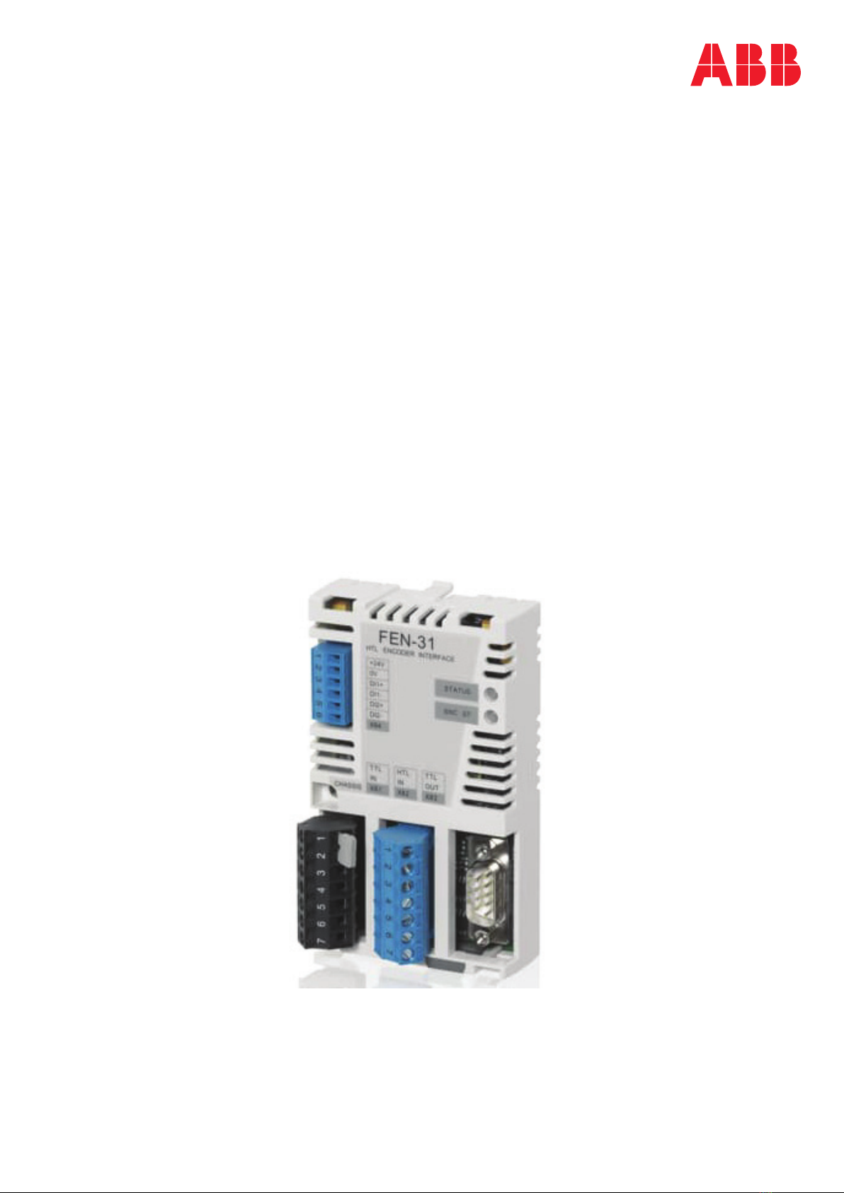
12FEN-31 HTL Encoder Interface .................................................................
13FEN-31 connections ...........................................................................
14Isolation areas .................................................................................
14Compatibility ......................................................................................
4 Installation
15Contents of this chapter ........................................................................
16Setting the supply voltage ......................................................................
17Mounting ...........................................................................................
17Terminal designations ...........................................................................
17Abbreviations ..................................................................................
17HTL supply voltage pin order (X81) ........................................................
18HTL input pin order (X82) ...................................................................
18TTL encoder emulation output pin order (X83) .........................................
19Digital latch input pin order (X84) .........................................................
19General encoder wiring guidelines ............................................................
20Wiring for differential push-pull HTL encoder ..........................................
21Wiring for single-ended push-pull HTL encoder ... .. .. .. .. .. .. .. .. .. .. .. .. .. .. .. .. .. .. .
22
Wiring for single-ended open collector HTL encoder and single ended open
emitter HTL encoder .........................................................................
24Configuring the internal pull-up resistor dip switches ... .. .. .. .. .. .. .. .. .. .. .. .. .
25TTL emulation output wiring (X83) ........................................................
26Position latch digital input wiring (X84) .................................................
27Power consumption and cable length ........................................................
28General encoder phasing principle ...........................................................
5 Start-up
29Contents of this chapter ........................................................................
29Programming ......................................................................................
6 Fault tracing
31Contents of this chapter ........................................................................
Table of contents 5

31Diagnostic LEDs ..................................................................................
31Cable fault diagnosis ............................................................................
7 Technical data
33Contents of this chapter ........................................................................
34Dimensions ........................................................................................
34General ..............................................................................................
34Connectors: ........................................................................................
35HTL encoder input (X81 and X82) .............................................................
35TTL encoder emulation output (X83) .........................................................
35Digital inputs for position latch (X84) .......................................................
Further information
6 Table of contents

Safety instructions
Contents of this chapter
The chapter contains the warning symbols and the safety instructions which you must
obey when you install or connect an optional module to a drive or converter. If you
ignore the safety instructions, injury, death or damage can occur. Read this chapter
before you start the installation.
Overview
This chapter states the general safety instructions that must be followed when
installing and operating the FEN-31.
In addition to the safety instructions given below, read the complete safety instructions
of the specific drive you are working on.
These warnings are intended for all who work on the drive. Ignoring the instructions
can cause physical injury or death, or damage the equipment.
General safety instructions
WARNING!
All electrical installation and maintenance work on the drive must be carried
out by qualified electricians only.
The drive and adjoining equipment must be properly earthed.
Do not attempt any work on a powered drive. After switching off the mains, always
allow the intermediate circuit capacitors 5 minutes to discharge before working on
the frequency converter, the motor or the motor cable. Check (with a voltage tester)
that the drive is in fact discharged before beginning work.
1
Safety instructions 7

The motor cable terminals of the drive are at a dangerously high voltage when mains
power is applied, regardless of motor operation.
There can be dangerous voltages inside the drive from external control circuits even
when the drive mains power is shut off.
Exercise appropriate care when working on the unit.
These warnings are intended for all who work on the drive. Ignoring the instructions
can cause physical injury or death, or damage the equipment.
For complete safety instructions see the drive manuals.
8 Safety instructions

Introduction
Contents of this chapter
This chapter introduces this manual.
Intended audience
The manual is intended for the people who are responsible for commissioning and
using the FEN-31. The reader is expected to have a basic knowledge of electrical
fundamentals, electrical wiring practices and how to operate the drive.
Before you start
It is assumed that the drive is installed and the drive power supply is switched off
before starting the installation of the extension module. Ensure that all dangerous
voltages connected from external control circuits to the inputs and outputs of the
drive are switched off.
In addition to conventional installation tools, have the drive manuals available during
the installation as they contain important information not included in this manual.
The drive manuals are referred to at various points of this document.
2
Introduction 9

10

Hardware description
Contents of this chapter
This chapter contains a short description of the FEN-31 HTL Encoder Interface.
3
Hardware description 11

FEN-31 HTL Encoder Interface
FEN-31 is an interface between the control board and an HTL encoder. It supports
various types of HTL encoders. A PTC, Pt1000 or KTY temperature sensor can be
attached to one of the connections of the FEN-31 interface.
FEN-31 offers an RS-422-standard-compliant TTL encoder emulation output and two
digital inputs. It also includes cable fault diagnostics for some HTL encoder types.
See the drive
Firmware manual
for details.
5
6
4
2
3
1
7
Digital latch inputs (X84)1
Fixing screw2
HTL encoder supply voltage (X81)3
HTL encoder input (X82)4
Diagnostic LEDs5
TTL emulation output (X83)6
Locking tab7
12 Hardware description

■FEN-31 connections
The following figure shows an overview of the connections of the FEN-31.
X84
X81 X82
X83
FEN-31
ACSXXX
ACSXXX
(optional)
Sensor
(optional)
Encoder
Hardware description 13

■Isolation areas
The following figure describes the different isolation areas of the module.
X83
X82
X81
X84
X201
B
A
2
3
4
6 7
1
5
Connection to the drive1
TTL encoder emulation output2
HTL encoder input3
HTL encoder supply voltage4
Digital latches5
Fixing screw6
CHASSIS7
The shields of connectors X81 and X82 and plug X83 are connected to chassis. The
fixing screw connects the chassis to ground.
Compatibility
FEN-31 is compatible with the following encoders:
• Differential push-pull HTL encoders
• Single-ended push-pull HTL encoders
• Open collector HTL encoders
• Open emitter HTL encoders
14 Hardware description

Installation
Contents of this chapter
This chapter contains instructions on installing the HTL Encoder Interface module.
WARNING!
Follow the safety instructions given in this guide and in the drive
Hardware
manual
.
4
Installation 15

Setting the supply voltage
WARNING!
Selecting the wrong supply voltage may damage or break the encoder.
Two supply voltages are available on pins 4 and 5 in connector X81. Only one of them
can be used to supply an encoder. The supply voltage is selected by placing a jumper
on connector X81 as described in the figure below. The following supply voltages can
be selected:
• +15 V DC ± 20% 200mA (max.)
• +24 V DC ± 20% 200mA (max.)
You can also connect an external 10 - 24 V DC power supply to pins 4 and 5 in connector
X81. In that case, the jumper must be removed.
12
3
45
6
7
12
3
45
6
7
12
3
45
6
7
+15 V +24 V External supply
Encoder supply voltage available on pins X81-4 and X81-5 with different jumper settings
16 Installation

Mounting
WARNING!
Before installation, do the electrical safety precautions given in section Safety
instructions.
Note: Before mounting the option module, set the supply voltage jumpers as described
above.
The option module is to be inserted into the option slot of the drive. See the drive
hardware manual for more information.
The module is held in place with plastic retaining clips, a locking tab and one screw.
The screw also provides the earthing of the cable shields connected to the module
and interconnects the GND signals of the module and the drive.
On installation of the module, the signal and power connection to the drive is
automatically made through a 20-pin connector.
Numbers in brackets refer to the layout drawing in section layout.
Mounting procedure:
1. Pull out the locking tab (7)
2. Insert the module carefully into the option slot until the retaining clips lock the
module into position
3. Push in the locking tab (7)
4. Fasten the screw (included) to the stand-off.
If you need to remove the adapter module after it has been installed into the drive,
use a suitable tool (e.g. small pliers) to carefully pull out the locking tab.
Note: Correct installation of the screw is essential for fulfilling the EMC requirements
and for proper operation of the module.
Terminal designations
■Abbreviations
Analog inputAI
Digital inputDI
Digital outputDO
Power outputPO
■HTL supply voltage pin order (X81)
DirectionDescriptionNamePin
Supply voltagePO+15V_B1
Encoder supply voltagePOVCC / external supply2
Supply voltagePO+24V_B3
Encoder supply voltagePOVCC / external supply4
0V, Common. Used for supply voltage 0 V and temperat-
ure sensor 0 V (PTC/Pt1000/KTY_0V).
-COM_B5
Installation 17

DirectionDescriptionNamePin
Temperature sensor (nonisolated)AIPTC/Pt1000/KTY-846
Shield-GND7
■HTL input pin order (X82)
DirectionDescriptionNamePin
A channelDIA+1
A channel - invertedDIA-2
B channelDIB+3
B channel - invertedDIB-4
Marker pulseDIZ+5
Marker pulse - invertedDIZ-6
Shield-GND7
■TTL encoder emulation output pin order (X83)
5
9 8 7 6
41
2
3
EM_A+
EM_A-
EM_B+
EM_B-
EM_Z+
EM_Z-
COM_BNC
COM_B
DirectionDescriptionNamePin
Channel A+DOEM_A+1
Channel B+DOEM_B+2
Channel Z+DOEM_Z+3
0V, CommonCOM_B4
Not connectedNC5
Channel A-EM_A-6
Channel B-EM_B-7
Channel Z-EM_Z-8
0V, CommonCOM_B9
ChassisShield-
18 Installation

■Digital latch input pin order (X84)
DirectionDescriptionNamePin
Supply voltagePO+24V_B1
CommonCOM_B2
Latch signal 1DIDI_1+3
Latch signal 1 returnDI_1-4
Latch signal 2DIDI_2+5
Latch signal 2 returnDI_2-6
General encoder wiring guidelines
The encoders should be connected to the encoder interface module with a shielded
instrumentation cable, preferably with twisted pairs. See the encoder manual for
additional requirements. To prevent the encoder inputs from being disturbed, the
cable shield must be connected to the chassis. The connection is made automatically
through the metal hood of the plug, if the cables are connected through the cable
clamp of the plug.
4
3
1 2
Metal hood1
Cable clamp2
Cable shield3
Cable bushing4
Note: Do not route the encoder cables parallel to power (e.g. motor) cables.
Tightening torque is 0.3 Nm (2.7 lbf·in.) for the plugs.
The allocation of cable pairs is described for each connector in the following sections.
Installation 19

■Wiring for differential push-pull HTL encoder
1
1
0
VCC0V
2
FEN-31
B+
B-
Z+
Z-
SHLD
2
0
1
2
3
4
5
6
A-
A+
7
X82
X81
15V
24V
1
2
3
4
5
6
7
+15V_B
VCC
+24V_B
VCC
COM_B
PTC/Pt1000/KTY-84
SHLD
PTC/Pt1000/KTY-84
PTC/Pt1000/KTY_0V
Encoder
Temperature
sensor
Connector plug and pin numberSignals nameCable pair number
X82-1A+
1X82-2A-
X82-3B+
2X82-4B-
X82-5Z+
3X82-6Z-
X81-4VCC
4X81-5COM_B
Note: If possible, connect encoder cable shield on motor side. When encoder cable
shield is connected on motor side, do not connect encoder cable shield to FEN.
20 Installation
Other manuals for FEN-31
2
Table of contents
Other ABB Recording Equipment manuals