ABB FEN-01 User manual

Quick guide - FEN-01
2
Quick guide - FEN-01
Introduction
This manual contains the very basic information about installing the
FEN-01 TTL Encoder Interface. For complete documentation see FEN-01
TTL Encoder Interface User’s Manual (3AFE68784603 [English]).
Safety instructions
WARNING! All electrical installation and maintenance work on the drive
must be carried out by qualified electricians.
The drive and adjoining equipment must be properly earthed.
Do not attempt any work on a powered drive. After switching off the
mains, always allow the intermediate circuit capacitors 5 minutes to
discharge before working on the frequency converter, the motor or the
motor cable. Lock out and tag out. Check (with a voltage tester) that the
drive is in fact discharged before beginning work.
These warnings are intended for all who work on the drive. Ignoring the
instructions can cause physical injury or death, or damage the
equipment.
For complete safety instructions see the drive manuals.
Compatibility
FEN-01 is compatible with the following encoders.
• TTL incremental encoder, 1…65535 pulses / rev, supports reference
mark
• TTL incremental encoder, 1...65535 pulses / rev, supports block
commutation and reference mark
Setting the supply voltage X301
WARNING! Selecting the wrong supply voltage may damage or break the
encoder.

Quick guide - FEN-01
3
The supply voltage for TTL encoders can be selected by vertically
mounted jumpers as described by the following figure.
Note: If an external power supply is used, the appropriate jumper must
be removed.
Note: If another FEN interface’s TTL emulation output is connected to
TTL input, the appropriate jumper must be removed.
Mounting
WARNING! Before installation, do the electrical safety precautions give
in section Safety instructions (Page 2).
Note: Before mounting the module, set the supply voltage jumpers as
described above.
Numbers in brackets refer to the layout drawing in section Layout and
connections (Page 5).
1. Pull out the locking tab (8).
2. Insert the module carefully into the option slot until the retaining clips
lock the module into position. Option slots are located on the drive
control unit.
3. Push in the locking tab (8).
4. Fasten the screw (included) to the stand-off.
If you need to remove the adapter module after it has been installed into
the drive, use a suitable tool (e.g. small pliers) to carefully pull out the
locking tab.
TTL Encoder (X31) TTL+ Encoder (X32)
+24 V +5.5 V +5.5 V +24 V

Quick guide - FEN-01
4
Note: Correct installation of the screw is essential for fulfilling the EMC
requirements and for proper operation of the module.
Wiring
WARNING! You can connect a motor temperature sensor to the encoder
module only if there is double or reinforced insulation between the live
parts of the motor and the sensor. The module does not provide a safe
isolation from the drive.
The encoders should be connected to the FEN-01 with a shielded
instrumentation cable, preferably with twisted pairs. See also the
encoder manual for additional requirements.
Tightening torque is 0.3 Nm (2.7 lbf·in.).
TTL encoder maximum cable length:
• 30 m with a 5 V encoder (0.5 mm2cable for power supply)
• 60 m with a 5 V encoder (two parallel 0.5 mm2cables for power
supply)
• 100 m with a 10…30 V TTL incremental encoder
TTL encoder emulation maximum cable length: 100 m
Note: Do not route the encoder cables parallel to power (e.g. motor)
cables.
Programming
The FEN-01 is programmed through drive parameters. These
parameters must be checked and adjusted according to the encoder
data sheet. For further information, see the drive Firmware manual.

Quick guide - FEN-01
5
Layout and connections
106 mm
2.48 in
1 Diagnostic LEDs
2Fixingscrew
3 TTL encoder input (X31)
4 TTL encoder input with commutation signal
support and PTC support (X32)
5 TTL encoder output (X33)
6 2 digital latch inputs (X34)
7 Encoder voltage selection jumper (X301)
8 Locking tab
1
2
3 4 5
6
7
4.17 in
63 mm 8
Optional
FEN-01
X31
A+
A-
B-
B+
Z+
Z-
VCC_ENC_1
COM_C
0V
VCC
VCC
0V
0
0
2
2
1
1
51
96
VCC_ENC_1
COM_C 4
5
9
8
3
7
2
6
1

Quick guide - FEN-01
6
FEN-01
X32
U+
U-
V-
V+
W+
W-
5
5
4
4
3
3
51
15 11
15
14
10
5
9
4
6
A+
A-
B-
B+
Z+
Z-
0
0
2
2
1
1
13
8
7
2
6
1
VCC_ENC_2
COM_B
SENSOR
0V
VCC
0V COM_B
PTC 3
11
12
10
Optional
FEN-01
X33
EM_A+
EM_A-
EM_B-
EM_B+
EM_Z+
EM_Z-
COM_B
COM_B
0V
0V
0V
0V
0
0
2
2
1
1
15
69
COM_B
COM_B 5
4
9
8
3
7
2
6
1
FEN-01
X34
DI1+
DI1-
DI2-
DI2+
VCC
COM_C
0V
VCC
2
2
1
1
2
1
6
5
4
3

Kurzanleitung - FEN-01
7
Kurzanleitung - FEN-01
Einleitung
Diese Anleitung enthält grundlegende Informationen zur Installation
des FEN-01 TTL-Inkrementalgeber-Schnittstellenmoduls. Vollständige
Dokumentation siehe FEN-01 TTL Encoder Interface User’s Manual
(3AFE68784603 [Englisch]).
Sicherheitsvorschriften
WARNUNG! Alle elektrischen Installations- und Wartungsarbeiten am
Frequenzumrichter müssen von qualifiziertem Fachpersonal ausgeführt
werden.
Der Antrieb und angeschlossene Einrichtungen müssen ordnungsgemäß
geerdet werden.
Arbeiten Sie nicht an einem Frequenzumrichter, der an die Spannungs-
versorgung angeschlossen ist. Warten Sie nach dem Abschalten der
Spannungsversorgung stets 5 Minuten, damit sich die Zwischenkreis-
kondensatoren entladen können, bevor Sie mit Arbeiten am Frequen-
zumrichter, dem Motor oder dem Motorkabel beginnen. Verriegeln und
markieren. Prüfen Sie vor Beginn der Arbeiten (mit einem Spannungs-
messgerät), ob der Frequenzumrichter tatsächlich spannungsfrei ist.
Diese Warnungen gelten für alle Personen, die an dem Antrieb arbeiten.
Die Nichtbeachtung kann zu schweren Verletzungen oder tödlichen
Unfällen führen und/oder Schäden an den Geräten verursachen.
Die vollständigen Sicherheitsvorschriften finden Sie in den Handbüchern
der Frequenzumrichter.
Kompatibilität
FEN-01 ist mit folgenden Inkrementalgebern kompatibel.
• TTL-Inkrementalgeber, 1…65535 Inkremente / Umdrehung,
unterstützt einen Null-Impuls.
• TTL-Inkrementalgeber, 1…65535 Inkremente / Umdrehung,
unterstützt die Blockkommutierung und Referenzmarke
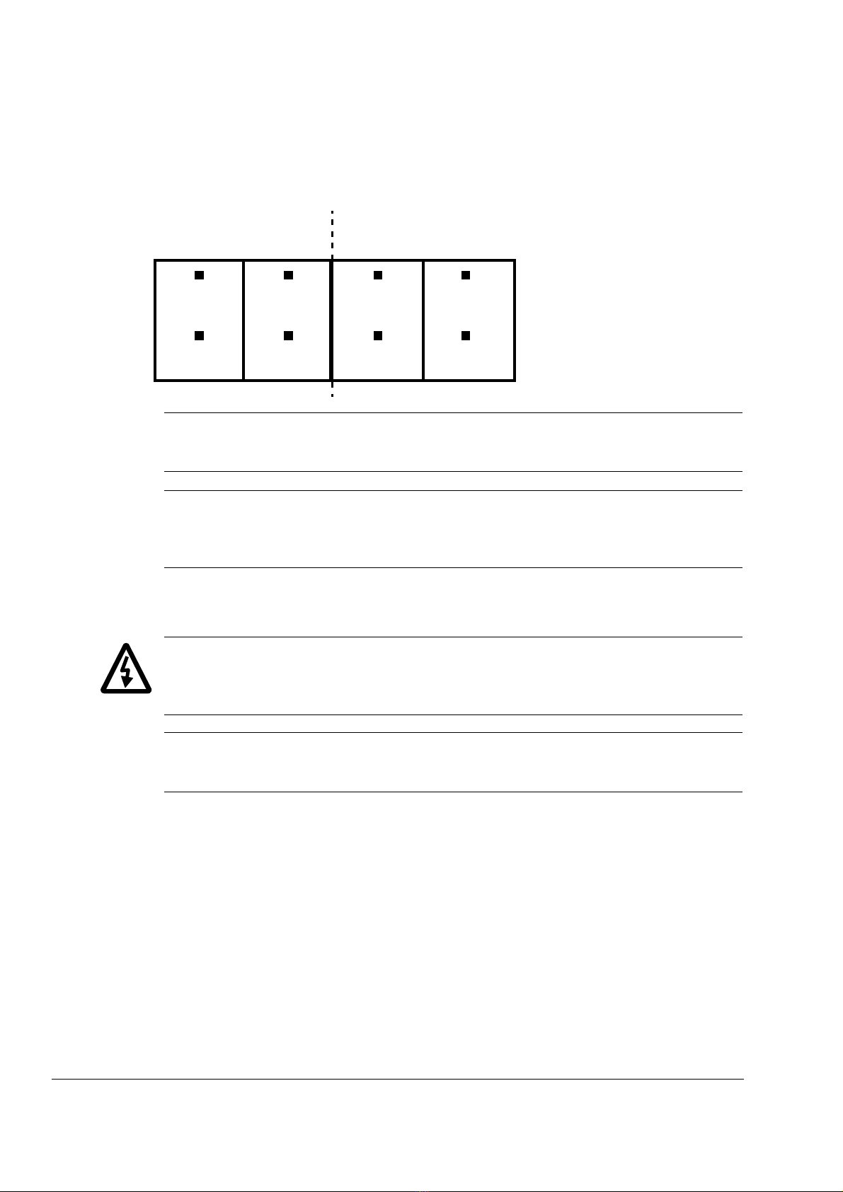
Einstellen der Versorgungsspannung X301
WARNUNG! Eine falsch eingestellte Versorgungsspannung kann zur
Beschädigung des Inkrementalgebers führen.

Kurzanleitung - FEN-01
8
Die Versorgungsspannung für TTL-Inkrementalgeber kann mit denvertikal
angeordneten Steckbrücken (Jumpern) eingestellt werden (siehe folgende
Abbildung).
Hinweis: Bei Verwendung einer externen Spannungsversorgung
mussder entsprechende Jumper entfernt werden.
Hinweis: Wenn der TTL-Emulationsausgang eines anderen FEN-
Schnittstellenmodulsan den TTL-Eingang angeschlossen wird,
muss der entsprechende Jumper entfernt werden.
Montage
WARNUNG! Führen Sie vor Beginn der Montagearbeiten die in Abschnitt
Sicherheitsvorschriften (Page 7) beschriebenen Sicherheitsmaßnahmen
durch.
Hinweis: Vor der Montage des Moduls die Jumper zur Einstellung
derVersorgungsspannung, wie oben beschrieben, einstecken.
Die in Klammern stehenden Zahlen beziehen sich auf die Layoutzeichnung
in Abschnitt Aufbau und Anschlüsse (Page 10).
1. Ziehen Sie die Verriegelungsnase (8) heraus.
2. Drücken Sie das Modul vorsichtig in den Optionssteckplatz hinein, bis
die Halteklammern des Moduls einrasten. Die Optionssteckplätze
befinden sich auf der Regelungseinheit des Frequenzumrichters.
3. Die Verriegelungsnase hineindrücken (8).
4. Befestigen Sie das Modul mit der Schraube (mitgeliefert).
Wenn das Adaptermodul nach dem Einbau in den Frequenzumrichter
entfernt werden muss, verwenden Sie ein geeignetes Werkzeug (z. B.
eine kleine Zange), um die Verriegelungsnase vorsichtig herauszuziehen.
TTL-Inkrementalge-
ber (X31) TTL+ Inkrementalge-
ber (X32)
+24 V +5,5 V +5,5 V +24 V

Kurzanleitung - FEN-01
9
Hinweis: Die korrekte Installation der Schraube ist zur Erfüllung der
EMV-Anforderungen und für einen ordnungsgemäßen Betrieb des
Moduls wichtig.
Verdrahtung
WARNUNG! An das Inkrementalgebermodul kann nur dann ein
Motortemperatursensor angeschlossen werden, wenn zwischen den
spannungsführenden Teilen des Motors und dem Sensor eine doppelte
oder verstärkte Isolierung vorhanden ist. Das Modul ermöglicht keine
sichere Trennung vom Frequenzumrichter.
Die Geber müssen mit einem geschirmten Instrumentenkabel,
vorzugsweise verdrillten Leiterpaaren, an das FEN-01 angeschlossen
werden. Zusätzliche Anforderungen siehe das Geberhandbuch.
Das Anzugsmoment beträgt 0,3 Nm (2,7 lbf·in.).
Maximale Kabellänge für den TTL-Inkrementalgeber:
• 30 m bei einem Geber mit 5 V (0,5 mm2Kabel für die Spannungsver-
sorgung)
• 60 m bei einem Geber mit 5 V (zwei parallele 0,5 mm2Kabel für die
Spannungsversorgung)
• 100 m bei einem TTL-Inkrementalgeber mit 10…30 V
Maximale Kabellänge für die TTL-Inkrementalgeberemulation: 100 m
Hinweis: Die Geberkabel dürfen nicht parallel zu Leistungskabeln
(z. B. Motorkabeln) verlegt werden.
Programmierung
Das FEN-01 wird über die Frequenzumrichter-Parameter programmiert.
Diese Parameter müssen geprüft und entsprechend dem Geberdatenblatt
eingestellt werden. Weitere Informationen enthält das Firmware-Hand-
buch des Frequenzumrichters.

Kurzanleitung - FEN-01
10
Aufbau und Anschlüsse
106 mm
2,48 in
1 Diagnose-LEDs
2 Befestigungsschraube
3 TTL-Inkrementalgebereingang (X31)
4 TTL-Inkrementalgebereingang mit Kommutie-
rungssignal- und PTC-Unterstützung (X32)
5 TTL-Inkrementalgeberausgang (X33)
6 2 digitale Referenziersignaleingänge (X34)
7 Jumper für Inkrementalgeber-Spannungsauswahl
(X301)
8 Verriegelungsnase
1
2
3 4 5
6
7
4,17 in
63 mm 8
Optional
FEN-01
X31
A+
A-
B-
B+
Z+
Z-
VCC_ENC_1
COM_C
0V
VCC
VCC
0V
0
0
2
2
1
1
51
96
VCC_ENC_1
COM_C 4
5
9
8
3
7
2
6
1

Kurzanleitung - FEN-01
11
FEN-01
X32
U+
U-
V-
V+
W+
W-
5
5
4
4
3
3
51
15 11
15
14
10
5
9
4
6
A+
A-
B-
B+
Z+
Z-
0
0
2
2
1
1
13
8
7
2
6
1
VCC_ENC_2
COM_B
SENSOR
0V
VCC
0V COM_B
PTC 3
11
12
10
Optional
FEN-01
X33
EM_A+
EM_A-
EM_B-
EM_B+
EM_Z+
EM_Z-
COM_B
COM_B
0V
0V
0V
0V
0
0
2
2
1
1
15
69
COM_B
COM_B 5
4
9
8
3
7
2
6
1
FEN-01
X34
DI1+
DI1-
DI2-
DI2+
VCC
COM_C
0V
VCC
2
2
1
1
2
1
6
5
4
3

Guida rapida - FEN-01
12
Guida rapida - FEN-01
Introduzione
Il presente manuale contiene le informazioni base sull'installazione-
dell'Interfaccia encoder FEN-01 TTL. Per una completa documentazione,
fare riferimento al Manuale utente Interfaccia Encoder FEN-01 TTL
(codice: 3AFE68784603).
Istruzioni di sicurezza
AVVERTENZA! Tutti gli interventi di installazione e manutenzione elettri-
casul convertitore di frequenza devono essere eseguiti esclusivamente
daelettricisti qualificati.
Il convertitore di frequenza e le apparecchiature collegate devono essere
adeguatamente messi a terra.
Non effettuare alcun intervento su un convertitore sotto tensione. Dopo
aver scollegato l'alimentazione, prima di intervenire sul convertitore di fre-
quenza, sul motore o sul cavo motore, attendere sempre cinque minuti per
consentire la scarica dei condensatori del circuito intermedio. Bloccare i
componenti e contrassegnarli adeguatamente. Verificare (con un misura-
tore di tensione) che il convertitore di frequenza sia effettivamente scarico.
Le seguenti avvertenze devono essere rispettate da tutti coloro
cheintervengono sul convertitore di frequenza. Il mancato rispetto
di taliistruzioni può mettere a repentaglio l'incolumità delle persone,
conrischio di morte, o danneggiare le apparecchiature.
Per le istruzioni di sicurezza complete consultare i manuali delconvertitore
di frequenza.
Compatibilità
L’interfaccia FEN-01 è compatibile con i seguenti encoder.
• Encoder TTL incrementale, 1…65535 impulsi / giro, supporta tacca di
riferimento
• Encoder TTL incrementale, 1…65535 impulsi / giro, supporta
commutazione di blocco e tacca di riferimento
Impostazione della tensione di alimentazione X301
AVVERTENZA! L'errata selezione della tensione di alimentazione
potrebbedanneggiare o rompere l'encoder.

Guida rapida - FEN-01
13
La tensione di alimentazione per gli encoder TTL può essere selezionatadai
ponticelli montati verticalmente come mostra la figura seguente.
Nota: in caso di alimentazione esterna, rimuovere il ponticello adeguato.
Nota: se all'ingresso TTL è collegata un'altra uscita di emulazione
TTLdell'interfaccia FEN, rimuovere il ponticello adeguato.
Montaggio
AVVERTENZA! Prima dell’installazione, adottare le precauzioni per la
sicurezza elettrica riportate nella sezione Istruzioni di sicurezza (Page 12).
Nota: prima di montare il modulo, impostare i ponticelli della tensione
dialimentazione come descritto sopra.
I numeri tra parentesi si riferiscono alla configurazione della sezione
Configurazione e collegamenti (Page 15).
1. Estrarre la linguetta di blocco (8).
2. Inserire delicatamente il modulo nello slot finché le clip di fissaggio
non scattano, bloccandolo in posizione. Sull'unità di controllo del
convertitore di frequenza sono presenti slot opzionali.
3. Spingere la linguetta di blocco verso l'interno (8).
4. Fissare la vite (inclusa) all’isolatore.
Se occorre rimuovere il modulo adattatore dopo che è stato installato
nel convertitore, usare un utensile idoneo (ad es. pinze piccole) per
estrarre con cautela la linguetta di blocco.
Encoder TTL (X31). Encoder TTL+ (X32)
+24 V +5,5 V +5,5 V +24 V

Guida rapida - FEN-01
14
Nota: per garantire la conformità ai requisiti EMC e il buon funzionamento
del modulo è essenziale installare correttamente la vite.
Cablaggio
AVVERTENZA! È possibile collegare un sensore di temperatura del
motore al modulo encoder solo se è presente un isolamento doppio o
rinforzato tra il sensore e le parti sotto tensione del motore. Il modulo
non fornisce un isolamento sicuro dal convertitore di frequenza.
Gli encoder dovrebbero essere collegati all'interfaccia FEN-01 con uncavo
per strumentazione schermato, preferibilmente con doppiniintrecciati.
Per ulteriori informazioni consultare anche il manualedell'encoder.
La coppia di serraggio è 0,3 Nm (2,7 lbf·in).
Max. lunghezza cavo dell'encoder TTL:
• 30 m con encoder da 5 V (cavo da 0,5 mm2per alimentazione)
• 60 m con un encoder da 5 V (due cavi paralleli da 0,5 mm2
peralimentazione)
• 100 m con un encoder TTL incrementale da 10…30 V
Max. lunghezza cavo di emulazione encoder TTL: 100 m
Nota: non posare i cavi dell'encoder in parallelo ai cavi di alimentazione
(ad esempio del motore).
Programmazione
L'interfaccia FEN-01 è programmata mediante i parametri delconverti-
tore di frequenza. Tali parametri devono essere controllati ecorretti
secondo le specifiche tecniche dell'encoder. Per ulteriori informazioni,
fare riferimento al Manuale del firmware del convertitore di frequenza.

Guida rapida - FEN-01
15
Configurazione e collegamenti
106 mm
2,48 in
1 LED diagnostici
2 Vite di fissaggio
3 Ingresso encoder TTL (X31).
4 Ingresso encoder TTL con supporto segnale
dicommutazione e supporto PTC (X32)
5 Uscita encoder TTL (X33)
6 2 ingressi registrazione digitali (X34)
7 Ponticello di selezione tensione encoder (X301)
8 Linguetta di blocco
1
2
3 4 5
6
7
4,17 in
63 mm 8
opzionale
FEN-01
X31
A+
A-
B-
B+
Z+
Z-
VCC_ENC_1
COM_C
0V
VCC
VCC
0V
0
0
2
2
1
1
51
96
VCC_ENC_1
COM_C 4
5
9
8
3
7
2
6
1

Guida rapida - FEN-01
16
FEN-01
X32
U+
U-
V-
V+
W+
W-
5
5
4
4
3
3
51
15 11
15
14
10
5
9
4
6
A+
A-
B-
B+
Z+
Z-
0
0
2
2
1
1
13
8
7
2
6
1
VCC_ENC_2
COM_B
SENSORE
0V
VCC
0V COM_B
PTC 3
11
12
10
opzionale
FEN-01
X33
EM_A+
EM_A-
EM_B-
EM_B+
EM_Z+
EM_Z-
COM_B
COM_B
0V
0V
0V
0V
0
0
2
2
1
1
15
69
COM_B
COM_B 5
4
9
8
3
7
2
6
1
FEN-01
X34
DI1+
DI1-
DI2-
DI2+
VCC
COM_C
0V
VCC
2
2
1
1
2
1
6
5
4
3
Other manuals for FEN-01
3
Table of contents
Languages:
Other ABB Recording Equipment manuals
Popular Recording Equipment manuals by other brands

Analog Devices
Analog Devices Super Sequencer ADM1168 manual

Metso
Metso neles RCI9H2 Safety manual

IK Multimedia
IK Multimedia iRig Keys Pro user manual

Universal Audio
Universal Audio Ampex ATR-102 manual

cymatic audio
cymatic audio LR-16 quick start guide

Webasto
Webasto BlueCool Connect Operating and installation instructions

FJELLCOM
FJELLCOM AP Polygard Multi Sensor Board user manual

Pioneer
Pioneer PDR-W37 Elite operating instructions

Lenze AC Tech
Lenze AC Tech SMVector RS-485 LECOM Communication Module reference guide

Audient
Audient iD22 user manual

Interlogix
Interlogix ATS1290 Installation sheet

Sonic
Sonic Wave I user manual