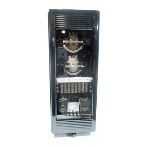
ABB CWC Manual

AIM
AN
ABB
Power
T
&
D
Company
Inc
.
Relay
Division
Coral
Springs
,
FL
33065
Instruction
Leaflet
I
.
L
.
41
-
242.4
F
Type
CWC
and
CWP
Directional
Ground
Relays
Effective
October
1975
Supersedes
I
.
L
.
41
-
242.4
E
dated
October
1973
^
Denotes
change
since
previous
issue
Before
putting
relays
into
service
,
re
-
shown
in
Fig
.
2
and
4
.
The
upper
pole
of
both
the
CWC
and
CWP
relays
are
tapped
.
In
addition
,
the
lower
pole
is
tapped
on
the
type
CWC
relay
.
CAUTION
move
all
blocking
which
may
have
been
inserted
for
the
purpose
of
securing
the
parts
during
shipment
,
make
sure
that
all
moving
parts
operate
freely
,
in
-
spect
the
contacts
to
see
that
they
are
clean
and
close
properly
,
and
operate
the
relay
to
check
the
settings
and
electrical
connections
.
The
electromagnets
are
connected
to
the
pro
-
tected
apparatus
in
a
manner
so
that
out
-
of
-
phase
fluxes
are
produced
by
the
flow
of
currents
in
both
the
upper
and
lower
pole
circuits
.
The
out
-
of
-
phase
fluxes
cause
either
a
contact
opening
or
a
contact
closing
torque
depending
upon
the
relative
direction
of
current
flow
in
the
upper
and
lower
pole
circuits
.
APPLICATION
The
type
CWC
and
CWP
relays
are
induction
disc
type
relays
used
for
directional
ground
fault
protec
-
tion
on
grounded
neutral
power
systems
.
The
type
CWC
relay
is
polarized
by
current
from
a
suitably
grounded
power
transformer
bank
neutral
.
Therefore
,
*
its
application
does
not
require
voltage
transformers
.
The
type
CWP
relay
is
voltage
polarized
by
residual
voltage
obtained
across
the
open
corner
of
the
delta
winding
of
a
grounded
wye
-
delta
voltage
transformer
.
PHASE
SHIFTER
NETWORK
The
phase
shifter
network
of
the
type
CWP
relay
consists
of
a
capacitor
and
resistor
connected
in
series
with
the
lower
pole
circuit
.
INDICATING
CONTACTOR
SWITCH
UNIT
(
ICS
)
At
stations
where
the
power
transformer
bank
netural
is
grounded
,
the
residual
voltage
will
be
small
generally
,
and
the
type
CWC
relay
is
recom
-
mended
.
At
ungrounded
stations
,
or
at
ground
stations
where
the
power
transformer
bank
neutral
is
not
avail
-
able
,
the
type
CWP
relay
is
applicable
.
The
d
-
c
indicating
contactor
switch
is
a
small
clapper
type
device
.
A
magnetic
armature
,
to
which
leaf
-
spring
mounted
contacts
are
attached
,
is
attacted
to
the
magnetic
core
upon
energization
of
the
switch
.
When
the
switch
closes
,
the
moving
contacts
bridge
two
stationary
contacts
,
completing
the
trip
circuit
.
Also
during
this
operation
two
fingers
on
the
armature
deflect
a
spring
located
on
the
front
of
the
switch
,
which
allows
the
operation
indicator
target
to
drop
.
The
target
is
reset
from
the
outside
of
the
case
by
a
push
rod
located
at
the
bottom
of
the
cover
.
CONSTRUCTION
The
type
CWC
and
CWP
relays
consists
of
an
operating
unit
,
an
indicating
contactor
switch
,
and
optional
indicating
instantaneous
trip
unit
,
addition
to
the
above
components
,
the
type
CWP
relay
has
a
phase
shifter
network
.
The
principal
compo
-
nent
parts
of
the
relay
and
their
locations
are
shown
in
Fig
.
1
-
8
.
In
The
front
spring
,
in
addition
to
holding
the
target
,
provides
restraint
for
the
armature
and
thus
controls
the
pickup
value
of
the
switch
.
INDICATING
INSTANTANEOUS
TRIP
UNIT
(
HT
)
OPERATING
UNIT
The
instantaneous
trip
unit
is
a
small
a
-
c
operat
-
ed
clapper
type
device
.
A
magnetic
armature
,
to
which
leaf
-
spring
mounted
contacts
are
attached
,
Is
This
unit
is
an
induction
disc
unit
with
an
elec
-
tromagnet
that
has
poles
above
and
below
the
disc
as
All
possible
contingencies
which
may
arise
during
installation
,
operation
or
maintenance
,
and
all
details
and
variations
of
this
equipment
do
not
purport
to
be
covered
by
these
instructions
.
If
further
information
is
desired
by
purchaser
regarding
this
particular
installation
,
operation
or
maintenance
of
this
equipment
,
the
local
ABB
Power
T
&
D
Company
Inc
.
representative
should
be
contacted
.
Printed
in
USA
.
Courtesy of NationalSwitchgear.com

TYPE
CWC
AND
CWP
RELAYS
IROtCATIHC
COHTACTO
*
svircii
IHPtCATIRft
COHTACTO
*
WITCH
HOLES
ivrn
POLES
LOVCt
POLE
LOVE
*
POLE
'
4
^
ilT
T
\
IHMCTIOH
WIT
liOUCTiO
*
urn
?
lUsK
*
.
ICS
1
/
1
iiir
LH
^
,
H
T
>
IHRICATIM
IISTAHTAMMS
INI
T
CHC
CHASSIS
OPEIATEP
SNorriM
WITOI
r
"
—
CMAUlS
OPEJUTD
SMOATlM
WITCH
•
ED
HAMLE
TEST
WITCH
OIMOTT
TffT
JAM
-
I
i
-
r
'
9
~
6
’
'
o
"
9
IEO
WHOLE
-
,
f
-
0
-
0
-
0
-
j
G
_
i
_
o
_
_
o
_
_
£
—
yiH
?
)
10
^
.
®
Id
©
®©
*
?
6
1
TEST
SHITCH
_
_
9
_
_
s
£
ir
9
.
_
vi
.
Jp
?
.
j
5
_
c
l
_
.
L
.
.
CMROT
TEST
JACK
1
1
W
7
TEHI
1
AL
TEMINAL
8
PROMT
VIIV
FRONT
VICV
fITU
taATlilE
IHSTAHTAREOVS
POLARlTT
AS
SHOW
.
THE
HAIR
CUTACTS
CLOSE
.
tim
IELAHVE
IHSTAHTAHCOVS
routin
'
AS
SHOW
,
THE
MAIH
CONTACTS
aOSE
.
5
T
-
D
-
7920
57
-
D
-
7921
Fig
.
5
.
internal
Schematic
of
Double
Trip
Type
CWC
Re
-
lay
in
the
Type
FT
-
21
Case
.
For
the
Single
Trip
Relay
the
Circuits
Associated
with
Terminal
2
ore
omitted
.
Fig
.
6
.
Internal
Schematic
of
the
Type
CWC
Relay
with
Indieating
Instantaneous
Trip
Unit
in
the
Type
FT
-
21
Case
.
product
which
is
the
minimum
pickup
product
of
two
equal
or
unequal
currents
.
Type
CWC
Relay
Ranges
and
taps
are
:
attracted
to
the
magnetic
core
upon
energization
of
the
switch
.
When
the
switch
closes
,
the
moving
con
-
tacts
bridge
two
stationary
contacts
completing
the
trip
circuit
.
Also
during
the
operation
two
fingers
on
the
armature
deflect
a
spring
located
on
the
front
of
the
switch
which
allows
the
operation
indicator
target
to
drop
.
The
target
is
reset
from
the
outside
of
the
case
by
a
push
rod
located
at
the
bottom
of
the
cover
.
.
25
to
4
Product
Range
Product
.
25
.
36
.
64
1.0
1.44
2.56
4.0
2.25
to
36
Product
Range
Product
2.25
4.0
6.25
9.0
16.0
25.0
36.0
A
core
screw
accessible
from
the
top
of
the
switch
provides
the
adjustable
pickup
range
.
The
minimum
and
maximum
pickup
points
are
indicated
on
the
scale
,
which
is
located
to
the
rear
of
the
core
screw
.
The
first
four
values
are
marked
on
the
lower
pole
tap
plate
.
The
upper
pole
tap
plate
is
marked
x
1
and
x
4
Product
.
The
last
four
values
are
obtained
by
using
the
x
4
tap
with
the
four
lower
pole
taps
.
OPERATION
AND
CHARACTERISTICS
Typical
60
Hertz
time
-
product
curves
for
the
type
CWC
relay
are
shown
in
Fig
.
9
.
These
curves
are
taken
at
maximum
torque
which
occurs
with
the
currents
in
phase
.
For
residual
and
Ground
currents
out
of
phase
the
relay
operating
time
may
be
obtained
by
determining
the
operating
time
corresponding
to
the
product
P
*
=
P
Cos
6
,
where
P
is
the
actual
relay
product
in
amperes
squared
,
and
9
is
the
angle
between
the
residual
and
polarizing
currents
.
*
The
operating
torque
for
the
CWC
relay
is
obtain
-
ed
by
energizing
the
lower
pole
coil
with
residual
current
(
usually
obtained
from
the
line
current
trans
-
former
)
and
the
2
tapped
upper
pole
coils
with
resid
-
ual
current
from
the
current
transformer
in
the
power
bank
neutral
.
For
the
CWP
relay
the
operating
torque
is
obtained
by
energizing
the
upper
pole
coils
with
residual
current
(
usually
obtained
from
the
line
cur
-
rent
transformer
)
and
the
lower
pole
with
residual
voltage
.
The
limits
for
which
these
curves
are
accurate
within
±
7
%
are
shown
in
Fig
.
10
.
TYPE
CWC
RELAY
TYPE
CWP
RELAY
The
type
CWC
relay
has
two
taps
on
the
upper
pole
and
four
on
the
lower
pole
.
They
are
marked
in
The
type
CWP
relay
taps
are
on
the
upper
pole
4
Courtesy of NationalSwitchgear.com

TYPE
CWC
AND
CWP
RELAYS
I
.
L
.
41
-
242.4
F
ivtiuTiae
CNTACTOt
Mi
Tea
laciiCiTias
coancroa
MITCH
LMK
NU
IflKt
POLE
ICS
ICS
,
\
tmt
POLE
^
UPPCI
POLE
C
*
P
_
LC
*
PJJC
3
u
I
IT
C
«
P
S
'
r
.
j
>
-
v
^
iflDuCTioa
uaiT
IBMCTIM
WIT
EP
-
laoiCiTiai
IIITAITAHEMS
TKIP
CHASSIS
OTEliTIO
M
0
CJIM
MITCH
SCO
HAWkE
CHASSIS
MSUtt
sawn
as
MI
yea
I
IT
SCO
HAAOLE
O
Q
0
0
0
O
0
6
_
0
_
A
A
_
i
_
i
®
®
(
D
^
©
©
©
.
©
r
'
9
9
"
6
o
'
"
<
5
~
y
y
”
y
"
i
7
T
-
K
*
T
Ml
Tea
9
0
9
9
9
9
£
HI
-
O
9
^
®
r
®
l
®
:
f
(
t
)
(
jj
)
©
/
®
@
>
-
^
-
^
11
^
TEST
SH
1
TCA
MttCBT
TEST
JACK
TEMIBAL
-
W
-
-
1
i
_
.
©
0
•
*
FRONT
VI
1
»
FRONT
VIEW
WITH
aCLATIVE
laSTASTAIEMS
POLAIITT
AS
SHOW
THE
NAia
COHTACTS
CLOSE
WITH
AELATI
1
E
lUTAHTAIEOUS
POUIITT
AS
SHOW
.
THE
HAlH
COHTACTS
CLOSE
183
AT
13
183
A
712
Fig
.
7
.
Internal
Schematic
of
the
Type
CWP
Relay
in
the
Type
FT
-
21
Case
.
For
the
Single
Trip
Relay
the
Circuits
Associated
with
Terminal
2
are
omitted
.
Fig
.
8
.
Internal
Schematic
of
the
Type
CWP
Relay
with
Indicating
/
nsfonfoneous
Trip
Unit
in
the
Type
FT
21
Case
.
safely
close
30
amperes
at
250
volts
d
-
c
,
and
will
carry
this
current
long
enough
to
trip
a
breaker
*
They
represent
the
minimum
pickup
product
of
current
times
voltage
at
maximum
torque
when
the
current
lags
the
voltage
by
60
°
.
The
range
and
taps
are
:
current
coil
.
The
indicating
contactor
switch
has
two
taps
that
provide
a
pickup
setting
of
0.2
or
2
amperes
,
change
taps
requires
connecting
the
lead
located
in
front
of
the
tap
block
to
the
desired
setting
by
means
of
a
screw
connection
.
To
Product
Range
Tap
Markings
20
-
150
20
30
40
50
75
100 150
75
-
600
75
100 150
200
300
400
600
TRIP
CIRCUIT
CONSTANT
Indicating
Contactor
Switch
(
ICS
)
*
Typical
60
Hertz
time
product
curves
for
the
type
CWP
relay
are
shown
in
Fig
.
11
.
These
curves
are
taken
at
maximum
torque
which
occurs
with
the
current
lagging
the
voltage
60
°
.
For
currents
not
lagging
by
this
angle
,
the
relay
tripping
time
may
be
obtained
by
determining
the
operating
time
correspond
-
ing
to
the
product
p
'
-
P
Cos
(
60
°
-
6
)
,
where
P
is
the
actual
relay
V
.
A
.
product
and
6
is
the
angle
the
current
lags
the
voltage
.
The
curves
are
accurate
within
±
17
c
if
the
multiple
of
tap
product
does
not
exceed
the
voltage
on
the
relay
coil
.
0.2
ampere
tap
6.5
ohms
d
-
c
resistance
2.0
ampere
tap
0.15
ohms
d
-
c
resistance
SETTING
CWC
INDUCTION
UNIT
Select
the
desired
upper
and
lower
pole
taps
.
Set
the
time
dial
by
applying
a
preselected
current
to
the
relay
coils
,
and
adjusting
the
dial
position
to
obtain
the
desired
time
of
operation
.
Alternatively
the
dial
may
be
set
by
inspection
,
if
the
timing
coordination
is
not
critical
.
TRIP
CIRCUIT
The
main
contacts
will
safely
close
30
amperes
at
250
volts
d
-
c
and
the
seal
-
in
contacts
of
the
in
-
dicating
contactor
switch
will
safely
carry
this
cur
-
rent
long
enough
to
trip
a
circuit
breaker
.
CWP
INDUCTION
UNIT
Select
the
desired
upper
pole
tap
.
position
by
applying
a
preselected
voltage
and
current
(
current
lagging
voltage
by
60
°
-
see
Fig
.
16
to
the
Set
the
dial
The
indicating
instantaneous
trip
contacts
will
5
Courtesy of NationalSwitchgear.com

TYPE
CWC
AND
CWP
RELAYS
?
0
10
0
S
5
4
3
2
I
I
.
8
•
n
o
.
5
x
o
.
4
o
ui
T
|
MC
DIAL
SETTIRC
in
.
3
z
ui
.
2
a
11
4
-
r
:
7
.
1
I
5
.
a
i
4
3
9
*
.
05
2
.
04
.
03
I
02
l
/
t
51
629
A
272
MULTIPLES
OF
TAP
PRODUCT
Fig
.
9
.
Typical
Time
Curves
of
the
Type
CWC
Relay
-
Current
Coils
in
Series
-
See
Fig
.
10
for
application
limits
.
The
nameplate
data
will
furnish
the
actual
cur
-
rent
range
that
‘
may
be
obtained
from
the
ITT
unit
.
relay
coils
and
adjusting
the
dial
position
to
obtain
-
ed
the
desired
time
of
operation
.
Alternatively
the
dial
may
be
set
by
inspection
,
if
the
timing
coordina
-
tion
is
not
critical
.
SETTING
CALCULATIONS
The
following
information
is
required
to
set
these
Indicating
Contactor
Switch
(
ICS
)
relays
:
No
setting
is
required
on
the
ICS
unit
except
the
selection
of
the
0.2
or
2.0
ampere
tap
setting
.
This
selection
is
made
by
connecting
the
lead
located
in
front
of
the
tap
block
to
the
desired
setting
by
means
of
the
connecting
screw
.
When
the
relay
energizes
a
125
or
250
volt
d
-
c
type
WL
relay
switch
,
or
equiva
-
lent
,
use
the
0.2
ampere
tap
;
for
48
volt
d
-
c
applica
-
tions
set
relay
in
2
tap
and
use
S
#
304
C
209
G
01
Type
WL
Relay
or
equivalent
.
INDICATING
INSTANTANEOUS
TRIP
(
IIT
)
1
.
The
maximum
and
minimum
ground
fault
current
for
faults
at
the
relay
and
at
the
remote
bus
.
These
values
should
be
residual
current
which
is
three
times
the
zero
sequence
current
.
2
.
The
maximum
and
minimum
polarizing
current
or
voltage
values
for
the
faults
above
.
The
values
should
be
residual
currents
or
voltage
which
are
three
times
the
zero
sequence
values
.
3
.
The
current
transformer
ratios
of
the
main
and
polarizing
current
transformers
for
the
type
CWC
relay
applications
or
the
main
current
transformer
ratio
and
the
polarizing
potential
transformer
ratio
for
the
type
CWP
relay
application
.
Since
the
minimum
and
maximum
markings
on
the
scale
only
indicate
the
working
range
of
the
core
screw
,
the
core
screw
must
be
adjusted
to
the
value
of
the
pickup
current
desired
.
6
Courtesy of NationalSwitchgear.com

I
.
L
.
41
-
242.4
F
TYPE
CWC
AND
CWP
RELAYS
For
the
2.25
to
36
Product
Range
For
the
0.25
to
4
Product
Range
I
^
LL
R
R
=
M
%
where
IL
=
the
lower
pole
current
.
IJJ
=
thfe
upper
pole
current
.
N
=
value
from
the
table
below
for
various
tap
combinations
.
where
IL
=
the
lower
pole
current
.
IJJ
=
the
upper
pole
current
.
M
=
value
from
the
table
below
for
various
tap
combinations
.
Upper
Pole
Product
Tap
Lower
Pole
Product
Tap
Tap
Upper
Pole
Product
Tap
Lower
Pole
Product
Tap
Tap
Product
N
K
K
M
Product
4.0
30
2.25
40
1.44
50
1.0
60
16.0
60
9.0
80
5.76
100
4.0
120
4.0
10
2.78
12
1.56
16
1.0
20
16.0
20
11.1
24
6.25
32
4.0
40
2.25
1
2.25
.
25
.
25
1
4.0
4.0
1
.
36
.
36
1
6.25
1
6.25
.
64
.
64
1
9.0
1
9.0
1.0
1.0
1
9.0
2.25
4
.
25
1.0
4
16.0
4.0
4
.
36
4
1.44
25.0
6.25
4
4
.
64
2.56
36.0
4
9.0
1.00
4
4
The
Typical
time
curves
for
the
Type
CWC
Relay
apply
if
the
values
of
R
falls
within
the
shaded
area
of
the
curve
above
,
and
if
neither
relay
current
is
greater
than
K
in
amperes
.
Ftg
.
10
.
Limits
for
Application
of
the
CWC
Time
Curves
.
7
Courtesy of NationalSwitchgear.com

TYPE
CWC
AND
CWP
RELAYS
20
10
6
6
S
4
3
2
I
<
/
>
o
8
u
UJ
CO
.
6
TIME
DIAL
SETTING
5
.
5
.
4
-
.
3
li
r
:
.
2
7
6
5
4
.
1
3
.
0
«
2
.
06
.
0
5
l
.
04
.
03
72
.
02
.
01
3
4
5
6 6
10
MULTIPLES
OF
TAP
PRODUCT
20
30
40
50
60
80
100
ISO
NOTE
:
CURVES
ARE
VALID
IF
THE
MULTIPLE
OF
THE
TAP
PRODUCT
(
VOLTS
-
AMPERES
)
DOES
NOT
EXCEED
THE
VOLTAGE
ON
THE
RELAY
POLARIZING
COILS
.
(
MADE
FROM
CURVE
538020
)
Curve
629
A
273
These
Curves
are
valid
if
the
multiple
of
tap
Product
(
volt
-
amperes
)
does
not
exceed
the
voltage
on
the
relay
polarizing
coils
.
Fig
.
11
.
Typical
Time
Curves
of
the
Type
CWP
Relay
at
Maximum
Torque
Angle
-
Curves
Apply
if
the
Multiple
of
Tap
Product
in
Volt
-
Amperes
Does
Not
Exceed
the
Polarizing
Voltage
in
Volts
.
8
Courtesy of NationalSwitchgear.com

I
.
L
.
41
-
242.4
F
TYPE
CWC
AND
CWP
RELAYS
STATION
A
STATION
C
STATION
B
(
3
)
CO
(
3
)
AA
—
°
-
ok
M
*
*
<
5
c
/
V
£
2
-
/
320
620
/
-
3
+
50
2
-
/
320
3
-
CUP
3
E
o
£
-
/
OO
3
-
36
,
fOO
^
!
/
-
£
9
/
0
2
-
/
0
+
0
Fig
.
12
.
Typical
System
for
Setting
Type
CWC
and
CWP
Relays
.
the
remote
line
or
bus
relay
operating
time
.
This
.
4
to
.
75
second
interval
is
known
as
the
coordinating
time
interval
.
It
includes
the
circuit
breaker
operat
-
ing
time
plus
a
factor
allowing
for
difference
between
actual
fault
currents
and
calculated
values
,
dif
-
ferences
in
individual
relay
performance
,
etc
.
For
8
cycle
breakers
the
value
of
.
4
second
is
commonly
used
,
while
for
30
cycle
breakers
,
.
75
second
is
used
.
Each
relay
should
be
set
to
operate
as
rapidly
as
possible
for
ground
faults
on
the
transmission
lines
near
the
breaker
.
The
product
available
for
the
relay
in
these
cases
should
be
large
enough
to
re
-
present
a
large
multiple
of
the
tap
product
value
so
the
operating
times
can
be
in
range
of
0.05
to
0.20
second
as
seen
from
the
curves
of
Figs
.
9
and
11
.
However
,
the
relays
cannot
distinguish
between
a
fault
on
the
line
near
the
remote
breaker
for
which
they
should
operate
,
and
a
similar
fault
on
the
bus
or
adjacent
line
for
which
they
should
not
operate
until
the
bus
differential
or
adjacent
line
relays
have
had
an
opportunity
to
operate
and
clear
the
fault
.
This
re
-
quires
an
increased
time
setting
of
the
relay
for
faults
near
the
remote
terminal
.
The
product
available
for
the
relay
in
these
cases
will
be
smaller
than
that
for
the
close
faults
and
should
represent
a
smaller
mul
-
tiple
of
the
tap
product
previously
chosen
so
the
op
-
erating
time
can
be
from
.
4
to
.
75
second
longer
than
As
an
example
,
a
type
CWC
relay
is
to
be
con
-
nected
at
Station
A
and
set
to
protect
the
line
running
to
Station
B
.
It
must
select
or
coordinate
with
the
type
CWP
relay
connected
at
Station
B
and
set
to
protect
the
line
running
to
Station
C
.
The
fault
cur
-
rent
and
voltage
for
single
line
-
to
-
ground
faults
under
minimum
conditions
for
this
system
are
shown
in
Fig
.
12
.
In
setting
the
type
CWC
and
CWP
relays
,
it
is
convenient
to
set
up
Table
as
shown
.
9
Courtesy of NationalSwitchgear.com

TYPE
CWC
AND
CWP
RELAYS
STATION
BuS
STATION
ouj
A
B
•
B
B
P
C
o
2
32
M
32
*
m
7
-
=
*
c
—
u
321
321
5
A
~
*
~
0
^
L
6
C
»
&
£
1
P
0
L
ae
»
p
a
oe
'
J
PHASE
RELAYS
}
-
PHASE
1
DELAYS
CONTACTS
CLOSE
i
22
3
V
0
~
-
VP
-
-
3
VQ
60
*
(
REF
)
I
POL
32
N
f
32
«
32
«
ill
:
501
»
+
T
'
r
^
t
9
-
lOP
8
I
CONTACT
CLOSES
PHASORS
SHOWN
FOR
MAX
.
CONTACT
CLOSE
TORQUE
.
«
0
”
0
52
5
i
SHOWN
FOR
MAX
.
CONTACT
CLOSE
TORQUE
TIT
ABC
UtN
Sl
'
P
»
.
IW
WHEN
SUPPLIES
A
B
C
'
ICt
NUMBER
CHARf
i
/
b
TRIP
BUS
DEVICE
NUMBER
CHART
DC
TRIP
BUS
70
S
.
POS
.
37
N
-
JJNAL
uKOUHO
RELAY
,
TYPE
CWC
32
N
*
DIRECTIONAL
8
R
0
UND
RELAY
,
TYPE
CWP
3
?
N
32
H
.
10
Y
~
-
LOWtU
POLt
WINUINC
OF
TYPE
CwC
32
N
10
32
N
—
-
LOWER
POU
WINDING
OF
TYPE
CWP
32
H
~
u
“
‘
yf
>
PtR
P
0
Lt
HI
HU
I
NOS
OF
TYPE
owe
IHUiLArIHG
IhSiANfAREUUS
TRIP
UNIT
52
-
PO
^
EA
CIRCUIT
SKEAKtK
INDICA
.
iNO
CuNfACfOR
SWITCH
J
-
e
:
.
t
«
AUK
AUXILIAKI
CONTACT
TC
-
Bi
<
EAKEK
TRIP
COIL
i
ics
;
32
N
ICS
SON
—
-
UPPER
POLE
WINDING
OF
TYPE
CWP
i
i
.
i
.
32
«
COLICS
J
2
»
_
^
:
IC
$
SON
:
|
:
50
B
SOB
-
INDICATING
INSTANTANEOUS
TRIP
UNIT
52
-
POWER
CIRCUIT
BREAKER
ICS
-
INDICATING
CONTACTOR
SWITCH
a
-
BREAKER
AUXILIARY
CONTACT
TC
-
BREAKER
TRIP
COIL
f
Ivi
32
N
^
'
32
M
A
32
1
J
i
J
*
—
s
?
a
sea
52
52
Tt
TC
NEC
.
NEB
.
1
1
$
+
A
137
182
A
804
*
3
C
Fig
.
14
.
External
Schematic
of
the
Type
CWP
Relay
for
Ground
Protection
.
*
Fig
.
73
.
External
Schematic
of
the
Type
CWC
Relay
for
Ground
Protection
.
TABLE
1
*
2
1
3
4
5
6
7
8
9
10
11
1 2
13
14
15
Line
Line
Relay
Fault
Primary
C
-
T
,
Location
No
.
Amps
.
Ratio
Polarizing
Polarizing
Primary
Amps
.
C
.
T
.
orP
.
T
.
or
Volts
Line
Polarizing
Secondary
Secondary
Product
I
-
Amps
.
(
ITJ
)
lv
x
IL
I
(
J
Multiples
Tap
of
Tap
Product
R
Time
Time
In
Dial
Seconds
Ratio
Amps
.
(
I
^
)
D
1
3450
300
/
5
2910
300
/
5
57.5
48.5
2780
1.19
36
77
4.76
2
.
11
D
2
1320
1040
22.0
17.3
381
1.27
10.6
5.1
.
52
F
1320
100
/
5
83
,
100
V
2
1000
/
1
66.0
83.1
V
5485
300
18
-
3
3
/
-
.
13
F
3
620
36
,
500
V
31.0
36.5
V
1130
3.8
.
53
The
relay
location
is
shown
in
Column
1
and
the
fault
location
in
Column
2
.
The
primary
line
residual
current
available
for
the
relay
is
recorded
in
Column
3
.
The
ratio
of
these
current
transformers
is
spec
-
ified
in
Column
4
.
Column
4
.
The
value
is
recorded
in
Column
7
.
The
upper
pole
relay
current
is
the
value
of
Column
5
divided
by
the
ratio
of
Column
6
,
and
is
recorded
in
Column
8
.
The
relay
operating
product
is
the
values
of
Column
7
and
8
multiplied
together
and
recorded
in
Column
9
.
For
the
type
CWC
relays
,
the
ratio
of
IL
/
IU
written
in
Column
10
.
All
of
this
data
is
fixed
by
and
is
*
.
.
.
*
•
/
ninary
to
making
the
actual
relay
setting
.
The
primary
fault
current
or
voltage
available
for
the
polarizing
winding
is
shown
in
Column
5
,
and
the
associated
current
or
potential
transformer
ratio
in
Column
6
.
All
of
these
fault
values
are
residual
values
or
three
times
the
zero
sequence
current
of
voltage
.
The
relay
current
for
the
lower
pole
wind
-
ings
is
the
value
of
Column
3
divided
by
the
ratio
of
system
constants
and
characteristics
.
The
choice
of
a
tap
recorded
in
Column
11
and
of
the
time
lever
in
Column
14
is
a
matter
of
trial
and
10
Courtesy of NationalSwitchgear.com

I
.
L
.
41
-
242.4
F
TYPE
CWC
AND
CWP
RELAYS
WYE
WINDINGS
TO
BE
PROTECTED
D
.
C
.
TRIP
BUS
87
N
|
e
«
E
"
m
—
A
POS
.
T
86
IH
=
j
jfsft
-
52
—
B
I
to
I
/
res
GROUND
IMG
RESISTOR
IF
USED
ALARM
X
87
N
XlCS
87
H
i
>
IOP
I
8
3
C
87
N
87
N
±
52
L
OTHER
RELAYS
a
i
87
M
87
N
87
M
+
87
N
52
6
0
7
86
JC
9
86
IPOL
MEG
.
AUX
C
/
T
DEVICE
NUMBER
CHART
87
N
-
GROUND
DIFFERENTIAL
RELAY
,
TYPE
CWC
87
N
—
-
LOWER
POLE
WINDING
CONTACT
CLOSES
87
N
IOP
“
jf
-
UPPER
POLE
WINDING
ICS
-
INDICATING
CONTACTOR
SWITCH
xPOL
86
-
AUXILIARY
TRIPPING
RELAY
,
TYPE
WL
52
-
POWER
CIRCUIT
BREAKER
BREAKER
AUXILIARY
CONTACT
TC
-
BREAKER
TRIP
COIL
SHOWN
FOR
MAX
CONTACT
CLOSE
TORQUE
a
184
A
156
*
Fig
.
15
.
External
Schematic
of
the
Type
CW
Relay
for
Ground
Differentia
/
Protection
of
Wye
or
Zig
-
zag
Winding
of
a
Transformer
or
Rotating
Machine
.
error
.
The
breakers
on
this
system
have
8
cycle
operating
time
so
that
the
coordinating
time
interval
should
be
about
.
4
second
.
The
tap
should
be
chosen
so
that
the
relay
times
for
the
close
-
in
fault
and
remote
fault
product
values
will
differ
by
about
the
coordinating
time
interval
or
.
4
second
in
this
case
.
Practically
this
can
be
accomplished
by
several
taps
with
equal
results
.
Tap
36
was
selected
in
this
example
.
The
product
value
divided
by
the
tap
is
recorded
in
Column
12
.
This
value
is
the
abscissa
of
the
time
product
relay
curves
.
From
these
curves
the
lever
Column
14
and
relay
operating
time
Column
15
were
chosen
so
that
the
relay
would
operate
at
about
.
12
second
for
close
-
in
faults
and
about
.
52
second
for
the
remote
faults
.
These
times
for
the
type
CWC
relay
were
obtained
using
time
dial
setting
%
.
With
the
selection
of
a
satisfactory
tap
value
,
the
curves
of
Fig
.
10
will
quickly
show
if
the
combination
of
#
tap
and
current
values
provide
relay
operating
times
as
indicated
by
the
curve
.
The
value
of
Column
10
multiplied
by
N
*
=
4.0
for
tap
36
gives
the
R
values
of
Column
13
.
These
are
within
the
curve
of
Figure
The
same
process
is
allowed
in
setting
the
type
CWP
relay
at
Station
B
on
breaker
F
.
Here
tap
300
was
selected
with
dial
to
provide
relay
operating
times
of
0.13
and
0.53
seconds
respectively
for
close
-
in
and
remote
faults
.
The
operating
limits
using
this
tap
are
fulfilled
since
neither
multiples
of
tap
prod
-
uct
value
(
Column
12
)
is
greater
than
the
polarizing
voltage
(
Column
8
)
.
After
individual
relay
settings
are
made
,
it
is
necessary
to
check
to
see
if
the
relays
select
prop
-
erly
with
associated
relays
.
In
the
example
the
coor
-
dinating
time
interval
was
0.4
second
.
Therefore
,
for
fault
2
,
the
relay
at
D
should
not
operate
before
the
relay
at
F
plus
the
coordinating
time
interval
.
In
other
words
,
the
operating
time
of
D
should
not
be
less
than
0.13
second
plus
0.4
=
0.53
second
Similarly
,
the
time
of
the
relay
at
breaker
H
should
not
be
greater
than
0.13
second
in
order
to
select
with
relay
F
for
fault
3
.
If
the
time
of
relay
H
is
greater
,
then
the
time
of
relay
at
F
must
be
in
-
creased
to
provide
proper
selection
.
This
change
may
10
.
Courtesy of NationalSwitchgear.com

TYPE
CWC
AND
CWP
RELAYS
ADJUSTMENTS
AND
MAINTENANCE
The
proper
adjustments
to
insure
correct
opera
-
tion
of
this
relay
have
been
made
at
the
factory
.
Upon
receipt
of
the
relay
no
customer
adjustments
,
other
than
those
covered
under
required
.
120
¥
01
T
TEST
SOURCE
ROTATION
1
,
2
,
3
SETTINGS
”
should
be
<
t
TYPE
CWP
REUT
(
FRONT
VIEW
)
0
'
PHASE
SNIFTER
ICS
For
relays
which
include
an
indicating
instanta
-
neous
trip
unit
(
IIT
)
,
the
junction
of
the
induction
and
indicating
instantaneous
trip
coils
is
brought
out
to
switch
jaw
#
3
.
With
this
arrangement
the
overcurrent
units
can
be
tested
separately
.
Acceptance
Check
PHASE
ANCLE
METER
VSIITCR
ICS
CIP
h
A
.
C
.
T
.
I
I
’
d
"
o
O
Vo
"
6
"
6
~
6
~
A
"
n
Of
i
_
Y
_
9
iL
0
_
°
-
2
4
-
9
!
!
•
.
4
nRHEOSTAT
Lh
®
_
©
9
'
® ©
©
©
©
\
S
&
mu
The
following
check
is
recommended
to
insure
that
the
relay
is
in
proper
working
order
.
NOTE
MAXIMUM
TORQUE
ANGLE
IN
THE
TRIPPING
DIRECTION
OCCURS
WHEN
THE
CURRENT
LEADS
THE
VOLTAGE
BY
300
*
WITH
CONNECTIONS
AS
SHOWN
.
1
.
Contact
By
turning
the
time
dial
,
move
the
moving
contacts
until
they
deflect
the
stationary
contact
to
a
position
where
the
stationary
contact
is
resting
against
its
backstop
.
The
index
mark
located
on
the
movement
frame
will
coincide
with
the
“
O
”
mark
on
the
time
dial
when
the
stationary
contact
has
moved
through
approximately
one
-
half
of
its
normal
deflec
-
tion
.
Therefore
,
with
the
stationary
contact
resting
against
the
backstop
,
the
index
mart
is
offset
to
the
right
of
the
“
O
”
mark
by
approximately
.
020
”
.
The
placement
of
the
various
time
dial
positions
in
line
with
the
index
mart
will
give
operating
times
as
shown
on
the
respective
time
-
current
curves
.
For
double
trip
relays
,
the
follow
on
the
stationary
con
-
tacts
should
be
approximately
1
/
32
”
.
18
UA
138
*
Fig
.
16
.
Diagram
of
Test
Connections
forthe
Type
CWP
Relay
in
FT
-
21
Case
.
be
accomplished
by
a
change
in
the
time
lever
setting
only
,
although
often
a
new
tap
and
lever
setting
may
provide
a
more
satisfactory
setting
.
Changing
the
setting
of
relays
at
B
probably
will
require
a
change
in
the
setting
of
the
relay
at
Station
A
.
After
the
setting
are
made
for
all
the
relays
under
minimum
generating
conditions
,
then
it
is
necessary
to
check
the
relay
operating
time
and
coordination
under
the
maximum
generating
conditions
.
Often
additional
changes
in
tap
and
dial
settings
are
re
-
quired
,
particularly
if
the
maximum
and
minimum
fault
values
are
quite
different
.
2
.
Minimum
Trip
Current
For
the
CWC
relay
,
connect
the
upper
and
lower
pole
coils
in
series
and
pass
a
current
equal
to
V
tap
product
x
multiplier
in
polarity
thru
both
coils
.
For
the
CWP
relay
connect
the
relay
as
per
Fig
.
16
and
apply
tap
value
product
.
The
moving
con
-
tacts
on
both
relays
should
close
within
5
%
of
the
applied
values
.
INSTALLATION
The
relays
should
be
mounted
on
switchboard
panels
or
their
equivalent
in
a
location
free
from
dirt
,
moisture
,
excessive
vibration
,
and
heat
.
Mount
the
relay
vertically
be
means
of
the
four
mounting
holes
on
the
glange
for
semi
-
flush
mountings
or
by
means
of
the
rear
mounting
stud
or
studs
for
projection
mounting
.
Either
a
mounting
stud
or
the
mounting
screws
may
be
utilized
for
grounding
the
relay
.
The
electrical
connections
may
be
made
directly
to
the
terminals
by
means
of
screws
for
steel
panel
mount
-
ing
or
to
the
terminal
studs
furnished
with
the
relay
for
thick
panel
mounting
.
The
terminal
studs
may
be
easily
removed
or
inserted
by
locking
two
nuts
on
the
stud
and
then
turning
the
proper
nut
with
a
wrench
.
3
.
Time
Curve
CWC
Relay
—
Connect
the
upper
and
lower
poles
in
series
and
pass
current
in
polarity
thru
both
coils
.
Set
the
time
dial
on
the
6
position
and
taps
on
.
25
or
2.25
product
and
1
multiplier
.
Check
several
points
on
the
time
curve
.
Timing
should
be
within
*
±
7
%
of
that
of
Figure
9
.
(
The
multiples
of
tap
pro
-
duct
shown
in
Figure
9
equal
the
square
of
the
current
thru
the
coils
divided
by
the
tap
product
.
)
For
detailed
FT
case
information
refer
to
I
.
L
.
41
-
076
.
12
Courtesy of NationalSwitchgear.com

I
.
L
.
41
-
242.4
F
TYPE
CWC
AND
CWP
RELAYS
position
where
the
stationary
contact
is
resting
against
its
backstop
.
The
index
mark
located
on
the
movement
frame
will
coincide
with
the
“
O
”
mark
on
the
time
dial
when
the
stationary
contact
has
moved
through
approximately
one
-
half
of
its
normal
deflec
-
tion
.
Therefore
,
with
the
stationary
contact
resting
against
the
backstop
,
the
index
mark
is
offset
to
the
right
of
the
“
O
'
*
mark
by
approximately
.
020
”
.
The
placement
of
the
various
time
dial
positions
in
line
with
the
index
mark
will
give
operating
times
as
shown
on
the
respective
time
-
current
curves
.
For
double
trip
relays
,
the
follow
on
the
stationary
contacts
should
be
approximately
1
/
32
”
.
CWP
Relay
-
Connect
the
relay
per
Figure
16
.
Set
the
time
dial
on
the
6
position
and
the
tap
in
the
20
or
75
product
.
Check
several
points
on
the
time
curve
by
applying
current
leading
the
voltage
by
300
°
.
The
timing
should
be
within
±
7
<
%
of
the
values
shown
on
Fig
.
11
.
4
.
Indicating
Instantaneous
Trip
Unit
(
IIT
)
The
core
screw
which
is
adjustable
from
the
top
of
the
trip
unit
determines
the
pickup
value
.
The
trip
unit
has
a
nominal
ratio
of
adjustment
of
1
to
4
and
an
accuracy
within
the
limits
of
10
*
%
.
The
making
of
the
contacts
and
target
in
-
dication
should
occur
at
approximately
the
same
in
-
stant
.
Position
the
stationary
contact
for
a
minimum
of
1
/
32
”
wipe
.
The
bridging
moving
contact
should
touch
both
stationary
contacts
simultaneously
.
2
.
Minimum
Trip
Current
Type
CWC
Relay
Connect
the
upper
and
lower
pole
coils
in
series
and
pass
current
in
polarity
on
both
coils
.
With
one
tap
screw
in
the
1
multiplier
position
and
the
other
screw
in
the
.
25
product
tap
for
the
.
25
-
4
product
range
or
the
2.25
product
tap
for
the
2.25
—
36
product
range
,
apply
current
and
adjust
the
spring
tension
so
that
the
contacts
just
close
at
tap
value
product
.
Apply
sufficient
current
to
operate
the
IIT
.
The
operation
indicator
target
should
drop
freely
.
5
.
Indicating
Contactor
Switch
(
ICS
)
Close
the
main
relay
contacts
and
pass
suf
-
ficient
d
-
c
current
through
the
trip
circuit
to
close
the
contacts
of
the
ICS
.
This
value
of
current
should
not
Type
CWP
Relay
-
Connect
the
relay
per
Fig
.
Set
in
the
lowest
tap
,
apply
100
volts
across
terminals
6
and
7
,
and
apply
minimum
pickup
current
,
leading
the
voltage
by
300
°
,
(
0.20
amperes
for
the
20
-
150
range
,
0.75
amperes
for
the
75
-
600
range
.
)
Then
,
adjust
the
spring
tension
so
that
the
contacts
just
close
.
16
.
be
greater
than
the
particular
ICS
tap
setting
being
used
,
freely
.
0.47
The
operation
indicator
target
should
drop
The
contact
gap
should
be
approximately
between
the
bridging
moving
contact
and
the
adjustable
stationary
contacts
.
The
bridging
moving
contact
should
touch
both
stationary
contacts
simul
-
taneously
.
>
»
3
.
Time
Curve
Calibration
Type
CWC
relay
—
Set
the
time
dial
to
posi
-
tion
6
and
the
product
tap
to
.
25
or
2.25
.
Set
the
mul
-
tiplier
tap
to
1
.
Connect
the
upper
and
lower
pole
coils
in
series
and
pass
a
current
equal
to
4
x
\
/
tap
product
in
polarity
thru
the
coils
.
Adjust
the
permanent
magnet
keeper
until
the
operating
time
is
between
.
95
and
1.01
seconds
.
Other
points
on
the
time
curve
of
Figure
9
should
be
within
±
1
%
of
the
values
shown
.
(
The
multiples
of
tap
product
shown
in
Figure
9
equal
the
square
of
the
current
passed
thru
the
coils
divided
by
the
tap
product
.
)
Routine
Maintenance
All
relays
should
be
inspected
and
checked
periodically
to
assure
proper
operation
.
All
contacts
should
be
periodically
cleaned
.
A
contact
burnisher
S
#
182
A
836
H
01
is
recommended
for
this
purpose
,
cleaning
contacts
is
not
recommended
,
because
of
the
danger
of
embedding
small
particles
in
the
face
of
the
soft
silver
and
thus
impairing
the
contact
.
The
use
of
abrasive
material
for
CALIBRATION
Type
CWP
Relay
-
Connect
the
relay
per
the
test
circuit
of
Fig
.
16
.
Set
the
6
time
dial
and
the
lowest
tap
.
Apply
100
volts
to
potential
coil
and
10
times
tap
current
.
(
Current
leading
voltage
by
300
°
)
.
relay
operate
between
1.43
and
1.51
seconds
.
Other
points
of
the
time
curve
should
be
within
±
7
%
of
the
value
shown
on
Fig
.
11
.
Use
the
following
procedure
for
calibrating
the
relay
if
the
relay
has
been
taken
apart
for
repairs
or
the
adjustments
disturbed
.
This
procedure
should
not
be
used
until
it
is
apparent
that
the
relay
is
not
in
proper
working
order
.
(
See
“
Acceptance
Check
”
)
.
1
.
Contact
4
.
Indicating
Contactor
Switch
(
ICS
)
By
turning
the
time
dial
,
move
the
moving
contacts
until
they
deflect
the
stationary
contact
to
a
Close
the
main
relay
contacts
and
pass
suf
-
13
Courtesy of NationalSwitchgear.com

TYPE
CWC
AND
CWP
RELAYS
ficient
d
-
c
current
through
the
trip
circuit
to
close
the
contacts
of
the
ICS
.
This
value
of
current
should
not
be
greater
than
the
particular
ICS
tap
setting
being
used
,
freely
.
CWP
The
burden
of
the
Type
CWC
relays
at
5
amperes
,
115
volts
,
60
Hertz
i
$
as
follows
:
The
operation
indicator
target
should
drop
Upper
Pole
Windings
5
.
Indicating
Instantaneous
Trip
Unit
(
IIT
)
P
.
F
.
.
Angle
Volt
-
Degrees
Value
Watts
Vars
.
Amperes
Lag
The
core
screw
must
be
adjusted
to
the
value
of
pickup
current
desired
.
The
nameplate
data
will
furnish
the
actual
current
range
that
may
be
obtained
from
the
ITT
unit
.
Product
Product
Range
Tap
0.660
0.560
0.495
0.460
0.370
0.340
0.290
12.6
75
0.633
0.557
0.494
0.460
0.370
0.340
0.290
0.144
0.095
0.043
0.032
0.013
0.006
75
-
600
9.8
100
RENEWAL
PARTS
5.0
150
Repair
work
can
be
done
most
satisfactorily
at
the
factory
.
However
,
interchangeable
parts
can
be
furnished
to
the
customers
who
are
equipped
for
doing
repair
work
.
When
ordering
parts
,
always
give
the
complete
nameplate
data
.
4.0
200
2.0
300
1.0
400
0.5
600
29.5
20
4.70
2.66
5.4
20
-
150
3.45
20.5
30
3.23
1.21
ENERGY
REQUIREMENTS
2.93
0.87
3.05
40
16.5
CWC
2.38
14.0
50
2.31
0.57
0.28
1
.
-
52
10.7
75
1.50
The
burden
of
the
Type
CWC
relays
at
5
amperes
,
*
60
Hertz
is
as
follows
:
0.11
1.15
5.5
100
1.15
0.80
0.014
0.80
1.0
150
Lower
Pole
Windings
Lower
Pole
Potential
Windings
P
.
F
.
Angle
Volt
-
Degrees
Amperes
Lag
(
between
relay
terminals
6
and
7
)
Product
Product
Range
Tap
P
.
F
.
Angle
Degrees
Lead
Value
Watts
Vars
19.5
82.7
29.3
88.0
Volt
-
Watts
Vars
.
Amperes
.
25
.
25
-
4
57.3
59.0
13.8
.
36
14.1
4.43
7.85
32.1
32.4
.
64
26.8
5.5
2.78
6.15
All
ranges
-
20.6
20.7
5.10
2.25
-
36
1.00
1.83
8.50
21.0
2.25
3.26
9.1
1.03
12.1
4.0
4.78
4.89
CWC
&
CWP
THERMAL
RATINGS
3.01
7.7
6.25
0.41
3.04
2.13
0.21
5.5
9.0
2.14
Pole
Winding
Continuous
Amperes
1
Sec
Amperes
Relay
Range
Upper
Pole
Windings
110
CWC
CWC
.
25
-
4
2
.
25
-
36
All
4
P
.
F
.
Angle
Degrees
Lag
280
Upper
Lower
10
Product
12.7
370
Volt
-
Amperes
Product
Range
Tap
Value
Watts
Vars
CWP
20
-
150
7
-
600
Upper
Upper
3.2
88
185
6.4
6.08
8.58
10.5
55
1
.
25
-
4
1.61
20
0.54
1.52
4
The
potential
coil
circuit
of
the
type
CWP
relay
will
stand
250
volts
for
15
seconds
.
50
1.24
0.79
0.95
2.25
-
36
1
0.21
17
0.20
0.06
4
14
Courtesy of NationalSwitchgear.com

I
.
L
.
41
-
242.4
F
TYPE
CWC
AND
CWP
RELAYS
.
563
.
250
(
14.30
)
DfA
.
4
HOLES
FOR
.
190
-
32
MT
6
.
SCREWS
*
-
5.563
-
*
>
(
141.30
)
(
6.35
)
H
-
6.063
^
|
(
I
54.00
)
1.594
(
40.49
)
2.781
(
70.64
)
f
t
J
L
5.219
(
132.56
)
9.688
(
246.08
)
9.063
(
230
,
188
)
i
4
4
-
“
t
4
4
T
4
,
4.531
(
115
*
09
)
4.844
(
123.04
)
10.438
(
265.13
)
\
L
\
i
l
|
.
125
l
-
2.938
(
74.63
)
-
3.188
(
80.98
)
I
I
(
3.18
)
"
•
k
5.875
(
149.23
)
<
1
K
6.375
-
^
(
161.93
)
PANEL
LOCATION
SEMI
-
FLUSH
MTG
.
PROJECTION
MTG
.
DIMENSIONS
IN
INCHES
DIMENSIONS
IN
MMX
\
H
_
ARGE
INTERNAL
\
Ka
EXTERNAL
\
/
VJOOTH
WASHER
—
SMALL
EXTERNAL
TOOTHED
WASHERS
.
PANEL
CUTOUT
8
DRILLING
FOR
SEMI
-
FLUSH
MTG
.
1.344
(
34.14
)
2.688
(
68.2
8
)
n
,
4
.
563
it
(
14.30
)
DIA
*
2
HOLES
-
5.375
(
136.53
)
4
-
f
.
OI
6
(
.
397
)
c
.
250
n
(
6.35
)
“
°
(
—
1.031
—
f
—
1.031
—
4
-
1.031
-
*
-
1.031
—
|
(
26.19
)
(
26.19
)(
26.19
)
(
26.19
)
1
.
190
-
32
SCREW
.
375
1
,
344
SPACERS
FOR
(
34.14
)
THIN
PANELS
(
9.53
)
R
PANEL
CASE
,
5
/
16
-
18
SCREW
CQ
.
(
FOR
THICK
PANELS
09
)
USE
5
/
16
-
18
STUDS
)
,
'
/
)
1.0
•
/
(
25.4
)
^
)
\
i
3
5
\
77
9
INTERNAL
-
EXTERNAL
TOOTHED
WASHERS
|
8
|
3
(
46.05
)
l
i
i
2.0
i
190
-
32
SCREW
FOR
THICK
PANELS
USE
.
190
-
32
STUDS
(
50.8
)
i
Wr
'
<
idv
2
4
6
8
i
1
V
\
1
hTr
DIA
'
~
H
r
*
—
516
(
19.05
)
U
,
A
‘
(
13.11
)
10
HOLES
OR
-
1.031
—
-
1.031
1.031
—
k
1.031
CUTOUT
(
26.19
)
(
26.19
)
(
26.19
)
(
26.19
)
PANEL
DRILLING
OR
CUTOUT
FOR
PROJECTION
MTG
.
(
FRONT
VIEW
)
.
750
tr
ptpQo
TERMINAL
NUMBER
.
641
TERMINAL
AND
MOUNTING
DETAILS
DIA
;
(
16.28
)
57
-
D
-
T
901
Fig
.
17
.
Outline
&
Drilling
Plan
for
the
Type
CWC
and
CWP
Relays
in
the
Type
FT
-
21
Case
.
Courtesy of NationalSwitchgear.com
Other manuals for CWC
1
This manual suits for next models
1
Table of contents
Other ABB Relay manuals

ABB
ABB REX 521 Use and care manual

ABB
ABB REJ 527 User manual

ABB
ABB ELR96 User manual

ABB
ABB RELION REX640 User manual

ABB
ABB Relion 611 Series Instructions for use
ABB
ABB RELION 650 SERIES User manual

ABB
ABB KLF-1 Manual

ABB
ABB AS400 User manual

ABB
ABB Relion 615 series User manual

ABB
ABB REX 521 User manual