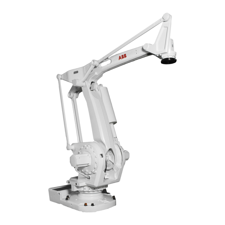
ABB IRB6400 Programming manual

Artisan Technology Group is your source for quality
new and certied-used/pre-owned equipment
• FAST SHIPPING AND
DELIVERY
• TENS OF THOUSANDS OF
IN-STOCK ITEMS
• EQUIPMENT DEMOS
• HUNDREDS OF
MANUFACTURERS
SUPPORTED
• LEASING/MONTHLY
RENTALS
• ITAR CERTIFIED
SECURE ASSET SOLUTIONS
SERVICE CENTER REPAIRS
Experienced engineers and technicians on staff
at our full-service, in-house repair center
WE BUY USED EQUIPMENT
Sell your excess, underutilized, and idle used equipment
We also offer credit for buy-backs and trade-ins
www.artisantg.com/WeBuyEquipment
REMOTE INSPECTION
Remotely inspect equipment before purchasing with
our interactive website at www.instraview.com
LOOKING FOR MORE INFORMATION?
Visit us on the web at www.artisantg.com for more
information on price quotations, drivers, technical
specications, manuals, and documentation
Contact us: (888) 88-SOURCE | sales@artisantg.com | www.artisantg.com
SM
View
Instra

ELECTRICAL
TROUBLESHOOTING
MANUAL
FOR
IRB6400
INDUSTRIAL ROBOT
&
S4 CONTROL SYSTEM
Effective Date: December 1, 1995
FlexibleAutomationInc.
1250 Brown Road
Auburn Hills, Mich. 48326
(810) 391-9000
Manual Part #7000722
Artisan Technology Group - Quality Instrumentation ... Guaranteed | (888) 88-SOURCE | www.artisantg.com

CAUTION
Donotperformanyworkcoveredinthismanualuntilyouhavereaditthrough
completelyandunderstandeachstepintheprocedure. Besureelectricalmain
disconnectis lockedout beforestartingany workon thissystem.
NOTE
Theinformationinthisdocumentissubjecttochangewithoutnoticeandshould
not be construed as a commitment by ABB Flexible Automation Inc. ABB
assumesno responsibility foranyerrors that mayappear in thisdocument.
In no event shall ABB Flexible Automation Inc. be liable for incidental or
consequentialdamages arisingfrom theuse ofthis documentof thesoftware
andhardware describedin thisdocument.
Thematerial inthis documentand mustnotbereproducedorcopiedinwhole
or in part without the written permission of ABB Flexible Automation Inc. The
contentsofthisdocument mustnotbeimpartedtoathirdpartynorbeusedfor
anyunauthorizedpurpose. Contraventionwillbeprosecuted.
Additional copies of this document may be obtained from ABB Flexible
Automationat its thencurrentcharge.
© ABB Flexible Automation Inc.
PartNumber: 7000722
ABBFlexible Automation Inc.
AuburnHills, Michigan USA
Artisan Technology Group - Quality Instrumentation ... Guaranteed | (888) 88-SOURCE | www.artisantg.com
Table of Contents TOC - I
TABLE OF CONTENTS ......................................... TOC - I
INTRODUCTION .............................................................. i
IDENTIFICATION............................................................ ii
MAINTENANCE ............................................................. iii
TOOLS .......................................................................... iv
THISMANUAL ............................................................... v
CHAPTERDESCRIPTIONS ........................................... vi
APPENDICESDESCRIPTIONS ...................................... vii
SIGNS AND SYMBOLS ................................................ viii
1. Safety......................................................................1-3
1.1 GeneralSafety .................................................. 1-4
1.2 SafetyFeatures ................................................ 1-5
1.3 SafetyGuidelines ............................................. 1-6
1.4 Safety During Maintenance .............................. 1-8
1.5 SafetyDuring Programming ............................. 1-8
1.6 Safety Control Chain of Operation .................... 1-9
1.7 Risks Associated with Live Parts ....................1-11
1.8 Limitation of Liability ....................................... 1-12
1.9 RelatedInformation ......................................... 1-12
2. Computer System ..................................................2-3
2.1 Overview .......................................................... 2-3
Diagram2-1 Computer Systemand SystemBoards ... 2-3
2.2 SystemDescription .......................................... 2-4
Diagram2-2 BlockDiagram ....................................... 2-5
2.3 Troubleshooting ............................................... 2-6
2.3.1 General..............................................................2-6
2.3.2 Diagnostics ........................................................2-8
2.4 BoardDescriptions.......................................... 2-10
2.4.1 Robot Computer DSQC 326..............................2-11
2.4.2 Main Computer DSQC 316................................2-12
2.4.3 Memory BoardDSQC 317/6 Mb (DSQC 321/4Mb)2-13
2.4.4 Power Supply Unit DSQC 258...........................2-14
2.4.5 System Board DSQC 256A................................2-15
2.4.6 Digital I/O Board DSQC 223..............................2-17
2.4.7 Combined I/O Board DSQC 315........................2-18
2.4.8 Analog I/O Board DSQC 209.............................2-19
2.4.9 Remote I/O Board DSQC 239............................2-20
2.4.10 Axis Board DSQC 233.......................................2-21
2.5 SerialMeasurement Board (SMB) ....................2-22
2.6 TeachPendant................................................. 2-23
2.7 Component Cross Reference ..........................2-24
2.8 List of Circuit Diagrams ................................... 2-25
2.9 Component Location Figures ..........................2-47
TABLEOFCONTENTS
Artisan Technology Group - Quality Instrumentation ... Guaranteed | (888) 88-SOURCE | www.artisantg.com
TOC - II Table of Contents
Figure 2-1 Control Cabinet...........................................2-47
Figure 2-2 Connectors .................................................2-49
Figure 2-3 SMB ...........................................................2-51
Figure 2-4 Back Plane AP80........................................2-53
Figure 2-5 Teach Pendant............................................2-55
3. Loading System Software......................................3-3
3.1 Overview .......................................................... 3-3
3.2 FloppyDisk ...................................................... 3-4
3.3 Software Loading Procedure ............................ 3-5
3.4 ParameterLoading Procedure .......................... 3-8
3.5 ResolverRevolution Counter Update ............... 3-9
3.6 List of Circuit Diagrams ................................... 3-13
3.7 Component Location Figures ..........................3-17
Figure 3-1 Batteries .....................................................3-17
Figure 3-2 Floppy Disk Drive........................................3-19
Figure 3-3 Robot Calibration Position...........................3-21
4. Power ON ...............................................................4-3
4.1 Overview .......................................................... 4-3
4.2 ACPower Distribution ...................................... 4-4
4.3 DCPower Distribution ...................................... 4-5
4.4 Component Cross Reference ........................... 4-8
4.5 List of Circuit Diagrams .................................... 4-9
4.6 Component Location Figures ..........................4-23
Figure 4-1 Inside Front of Control Cabinet....................4-23
Figure 4-2 Inside Swing Gate.......................................4-25
Figure 4-3 Brake Push Buttons....................................4-27
Figure 4-4 Customer Connection XS3/XT3...................4-29
Figure 4-5 Operator's Panel.........................................4-31
5. Motor ON/Dual Run Chain......................................5-3
5.1 Overview .......................................................... 5-3
Diagram5-1 Computer System and System Board..... 5-4
5.2 Manual (Reduced or Full) Speed Mode Circuit .5-5
5.2.1 Run Chain 1.......................................................5-5
5.2.2 Run Chain 1 - Manual Stop Circuit...................... 5-6
5.2.3 Run Chain 1 - General Stop (GS) Circuit............. 5-7
5.2.4 Run Chain 1 - Emergency Stop (ES) Circuit........ 5-8
5.2.5 Run Chain 1 - Limit (LIM) Circuit......................... 5-9
5.2.6 Run Chain 1 - Completion..................................5-10
5.2.7 Run Chain 2......................................................5-11
5.2.8 Run Chain 2 - Manual Stop Circuit.....................5-12
5.2.9 Run Chain 2 - General Stop Circuit....................5-13
5.2.10 Run Chain 2 - Emergency Stop Circuit...............5-14
5.2.11 Run Chain 2 - Limit Circuit.................................5-15
5.2.12 Run Chain 2 - Completion..................................5-16
5.3 AUTO Mode Circuit .......................................... 5-17
5.3.1 Run Chain 1......................................................5-17
Table of Contents (Cont)Table of Contents (Cont)
Artisan Technology Group - Quality Instrumentation ... Guaranteed | (888) 88-SOURCE | www.artisantg.com

Table of Contents TOC - III
5.3.2 Run Chain 2......................................................5-18
5.4 Component Cross Reference ..........................5-19
5.5 List of Circuit Diagrams ................................... 5-21
5.6 Component Location Figures ..........................5-29
Figure 5-1 Computer System and System Board..........5-29
Figure 5-2 Back Plane AP80........................................5-31
Figure 5-3 System Board K1CR & K2CR......................5-33
Figure 5-4 Control Cable XS1......................................5-35
Figure 5-5 Customer Connections XS3/XT3 & AP41.....5-37
Figure 5-6 Operator's Panel.........................................5-39
Figure 5-7 Power Unit..................................................5-41
Figure 5-8 R1.MP ........................................................5-43
Figure 5-9 Teach Pendant............................................5-45
6. Emergency Stop.....................................................6-3
6.1 Overview .......................................................... 6-3
6.2 Emergency Stop - Run Chain 1 ......................... 6-4
6.3 Emergency Stop - Run Chain 2 ......................... 6-6
6.4 Emergency Stop - Reset Circuit ....................... 6-8
6.5 Component Cross Reference ........................... 6-9
6.6 List of Circuit Diagrams ................................... 6-11
6.7 Component Location Figures ..........................6-15
Figure 6-1 Teach Pendant............................................6-15
Figure 6-2 Computer System & System Board.............6-17
Figure 6-3 Back Plane AP80........................................6-19
Figure 6-4 Operator's Panel.........................................6-21
Figure 6-5 Customer Connections XS3/XT3.................6-23
7. Power Unit..............................................................7-3
7.1 Overview .......................................................... 7-3
7.2 KM1 .................................................................. 7-4
7.3 KM2 .................................................................. 7-5
7.4 KM3 .................................................................. 7-6
Diagram7-1 Rectifier Board ....................................... 7-7
7.5 KM4 .................................................................. 7-8
7.6 Component Cross Reference ........................... 7-9
7.7 List of Circuit Diagrams ................................... 7-11
7.8 Component Location Figures ..........................7-17
Figure 7-1 Power Unit..................................................7-17
Figure 7-2 XS3/XT3 and Connectors AP41 & AP9........7-19
Figure 7-3 K1CR & K2CR on System Board.................7-21
8. Brake Circuitry.......................................................8-3
8.1 Overview .......................................................... 8-3
8.2 Manual Brake Release Circuit ........................... 8-4
8.3 Motors ON Brake Release ................................ 8-5
8.4 Component Cross Reference ........................... 8-7
Table of Contents (Cont)Table of Contents (Cont)
Artisan Technology Group - Quality Instrumentation ... Guaranteed | (888) 88-SOURCE | www.artisantg.com

TOC - IV Table of Contents
8.5 List of Circuit Diagrams .................................... 8-9
8.6 Component Location Figures ..........................8-23
Figure 8-1 Power Unit..................................................8-23
Figure 8-2 System Board.............................................8-25
Figure 8-3 Robot Brake Buttons...................................8-27
Figure 8-4 Power System Board Connections..............8-29
Figure 8-5 Robot Axes.................................................8-31
9. Motor & Resolver Circuitry....................................9-3
9.1 Overview .......................................................... 9-3
Diagram9-1 ClosedLoop System.............................. 9-3
9.2 Computer.......................................................... 9-4
9.2.1 Main Computer...................................................9-4
9.2.2 Memory Board....................................................9-4
9.2.3 Robot Computer.................................................9-5
9.3 Drive System Boards ........................................ 9-6
9.3.1 Rectifier..............................................................9-6
Diagram9-2 Rectifier ................................................. 9-6
9.3.2 Drive Unit...........................................................9-8
Diagram9-3 Drive Board ........................................... 9-8
9.4 Motors .............................................................. 9-9
Diagram9-4 SimplifiedMotor ..................................... 9-9
Diagram9-5 'Y'Motor WiringConfiguration ...............9-10
9.5 Resolver .......................................................... 9-12
Diagram9-6 ResolverCoilRelationships...................9-12
9.6 SerialMeasurement Board (SMB) ....................9-13
9.7 Component Cross Reference ..........................9-15
9.8 List of Circuit Diagrams ................................... 9-17
9.9 Component Location Figures ..........................9-31
Figure 9-1 Back Plane AP80........................................9-31
Figure 9-2 Drive System Boards..................................9-33
Figure 9-3 Robot Axis Motors.......................................9-35
Figure 9-4 Drive Connectors........................................9-37
10. Calibration Procedures........................................10-3
10.1 Overview ......................................................... 10-3
10.2 "Rough" Resolver Calibration Procedure ........10-4
10.3 ManuallyEntering Calibration Values ............10-10
10.4 PrecisionResolver Calibration Procedure ....10-14
10.4.1 Calibrating Axis 1............................................10-15
10.4.2 Calibrating Axis 2-6.........................................10-16
10.5 CounterUpdating Procedure ......................... 10-23
11. Inputs & Outputs..................................................11-3
11.1 Overview ......................................................... 11-3
11.2 I/OBoards ....................................................... 11-4
11.2.1 Digital I/O Board DSQC 223..............................11-4
11.2.2 Analog I/O Board DSQC 209.............................11-5
Table of Contents (Cont)Table of Contents (Cont)
Artisan Technology Group - Quality Instrumentation ... Guaranteed | (888) 88-SOURCE | www.artisantg.com
Table of Contents TOC - V
Table of Contents (Cont)Table of Contents (Cont)
11.2.3 Combined I/O Board DSQC 315........................11-6
11.2.4 Remote I/O Board DSQC 239............................11-7
11.3 BoardConnections .......................................... 11-8
11.3.1 External I/O Connections (Conn. option 31X).....11-9
11.3.2 Internal I/O Connections (Conn. option 34X)....11-13
11.3.3 Relay Unit (Conn. option 37X).........................11-16
11.3.4 120 VAC Modules (Conn. option 35X)..............11-18
11.3.5 Manually Operated I/O.....................................11-19
11.4 Component Cross Reference ........................ 11-21
11.5 List of Circuit Diagrams ................................. 11-23
11.6 Component Location Figures ........................ 11-41
Figure 11-1 XS3/XT3 ...................................................11-41
Figure 11-2 Screw Terminals.......................................11-43
Figure 11-3 120 VAC I/O Connector.............................11-45
A. ERROR MESSAGES..............................................A-2
A1. IndicatingErrors............................................... A-2
A2. Types of Error Messages .................................. A-3
A3. ErrorCodes ...................................................... A-7
A3.1 Operational Error Messages...............................A-7
A3.2 System Error Messages.....................................A-9
A3.3 Hardware Error Messages................................A-16
A3.4 Programming Error Messages..........................A-35
A3.5 Motion Error Messages.....................................A-59
A3.6 Operator Error Messages.................................A-67
A3.7 I/O & Communication Error Messages.............. A-69
B. PARTS LISTS.........................................................B-3
B1. Control System Parts List ................................ B-3
B1.1 Power Supply Side.............................................B-3
B1.2 Operator's Panel ................................................B-3
B-3
B1.3 Teach Pendant...................................................B-4
B1.4 Contactor Unit....................................................B-4
B1.5 Computer System...............................................B-4
B1.6 Drive System......................................................B-5
B1.7 Optional Units.....................................................B-5
B1.8 Miscellaneous ....................................................B-6
B2. Suggested Spare Parts List .............................. B-7
B2.1 Axis 1.................................................................B-7
B2.2 Axis 2 & 3...........................................................B-7
B2.3 Lower Arm..........................................................B-7
B2.4 Upper Arm..........................................................B-8
B2.5 Cables ...............................................................B-8
B2.6 Control...............................................................B-9
C. CONNECTORS & CABLES....................................C-3
C1. Robot Arm Cables ............................................ C-3
C2. ControlCabinet Cables .................................... C-4
Artisan Technology Group - Quality Instrumentation ... Guaranteed | (888) 88-SOURCE | www.artisantg.com

TOC - VI Table of Contents
C3. MiscellaneousCables ....................................... C-6
C4. Signal Cable, Axis 1 .......................................... C-7
C5. Signal Cable, Axis 5 .......................................... C-8
C6. Power Cable, Axis 5 .......................................... C-9
C7. Signal Cable, Axis 6 ........................................ C-10
C8. Power Cable, Axis 6 ........................................ C-11
C9. Signal Cable, Axis 2 ........................................ C-12
C10. Power Cable, Axis 2 ........................................ C-13
C11. Signal Cable, Axis 3 ........................................ C-14
C12. Power Cable, Axis 3 ........................................ C-15
C13. Control Cable, Signal ...................................... C-16
C14. ControlCable, Power ...................................... C-17
C15. CustomerCable, Signal .................................. C-18
C16. Customer Cable, Power .................................. C-19
C17. Lower Cable Assembly ................................... C-20
C18. Upper Cable Assembly ................................... C-22
C19. Cable, Customer Connection .......................... C-24
C20. Cable,M94A ................................................... C-25
C21. Cable, M94A Control Wiring X-Reference ....... C-30
C22. Connectors ..................................................... C-35
D. GLOSSARY............................................................D-1
E. CIRCUIT DIAGRAMS.............................................E-3
E1. SheetNumbering .............................................. E-3
E2. ConnectorLabeling .......................................... E-4
E3. ComponentLabeling ........................................ E-5
E4. SheetReferencing ............................................ E-6
E5. RelayLabeling .................................................. E-7
E6. Key Switch Contacts ........................................ E-8
E7. Symbolsand Abbreviations ............................. E-9
Table of Contents (Cont)Table of Contents (Cont)
Artisan Technology Group - Quality Instrumentation ... Guaranteed | (888) 88-SOURCE | www.artisantg.com

Introduction
Introduction-i
Electrical
TroubleshootingGuide
IRB6400M94A
INTRODUCTION
ThisTroubleshootingManualprovidesthedataandproceduresrequired
toservicetheABBFlexibleAutomationIRB6400IndustrialRobotwithS4
Control. Additional supplemental manuals specific to special features
may also have to be referred to if such special features and equipment
are a part of the robot purchase. Such manuals are included with these
features.
This manual is specific to IRB6400 robots having schematic wiring
diagram number CAB M94A-50xxx-00.
This manual was written to be part of an instructor-guided training
program for experienced electricians only. The robot owner/user is
responsible for the training of personnel to safely and successfully
service the IRB6400 Industrial Robot.
Thedatacontainedinthismanualwasoriginatedbyandistheexclusive
propertyofABBFlexibleAutomation.Themanualisfurnishedforowner/
user information only and is neither a license for reproduction nor an
authorization to furnish the information to others.
PersonnelservicingtheIRB6400IndustrialRobotshallreadandcomply
with the contents of this manual and all other manuals pertaining to the
IRB6400.Ifquestionsarise,contacttheregionalsalesandserviceoffice
at1-800-457-6268,fortheaddressandphonenumberofABBFlexible
Automation, Industrial Robot Division.
Artisan Technology Group - Quality Instrumentation ... Guaranteed | (888) 88-SOURCE | www.artisantg.com
Introduction
Electrical
TroubleshootingGuide
IRB6400M94A
Introduction-ii
The serial numbers can be found in the locations indicated in the
illustrations.Thesenumbersmustbereferencedinallmattersconcerning
the robot.
Figure 2. Identification plate
onthecontrolpanel.
IDENTIFICATION
Identification plates indicating the type of robot and manufacturing
number,etc.,arelocatedontherearoftherobot'slowerarm(seeFigure
1) and on the front of the controller above the operator's panel (see
Figure2).Theinstallationandsystemdiskettesarealsomarkedwiththe
robot type and manufacturing number (see Figure 3).
Type
Voltage
Frequency
Power
Ref.No
Man.No
Net weight
IRB
3 x 475 V
50-60 Hz
6.7 kVA
RXXX XXXX
A 31023
300 kg
Type: 6400 /2.4-120
ABB Flexible Automation
Label with
manufacturing number.
6400/M94A
6400-XXXX
Label with
type
Figure 3. Label on a system
diskette
S4 / M94A program
Program No3HAB XXXX-X
Boot Disk1 (2)
Serial NoIRB 6400-XXXX
PropertyofABBVasteras/Sweden.Allrightsreserved.Reproduction,
modification, use or disclosure to third parties without express
authorityisstrictlyforbidden.Copyright1994.
Authorizedtobeusedinthecontrollerswiththeabovestatedserial
no.
ABBFlexibleAutomation
ABB Flexible Automation Made in Sweden
Type-Manufacturing no. M94A
Nom load see instructions
Net weight IRB 6400 /
2.4-120 :1825 KG
2.4-150, 2.8-120 :1950 KG
3.0-75 :1950 KG
S /2.9-120 :2450 KG
PE /2.25-75 :1524 KG
Type IRB 6400 /2.4-120
Figure 1. Identification plate
on the manipulator.
Artisan Technology Group - Quality Instrumentation ... Guaranteed | (888) 88-SOURCE | www.artisantg.com
Introduction
Introduction-iii
Electrical
TroubleshootingGuide
IRB6400M94A
MAINTENANCE
WhatYouMustKnowBeforeYouUseTheRobot
Normal maintenance and repair work usually only requires standard
tools.Some repairs,however, requirespecifictools. Alist ofsuggested
Hand Tools is included in this introduction.
The main disconnect should be switched off whenever work is carried
out in the control cabinet. Note that even though the power is switched
off,the orange/yellow coloredcables maybe live.The reason forthis is
that these cables are connected to external equipment and are
consequently not affected by the main switch on the controller.
Circuitboards(printedboardsandcomponents)mustNEVERbe
handledwithoutElectro-Static-Discharge(ESD)protectionsuch
asa wrist strap,inorder not todamage them. Use thecarry bag
locatedontheinsideofthecontrollerdoor.
Allpersonnelworkingwiththerobotsystemmustbeveryfamiliar
withthesafetyregulationsoutlinedinChapter1(Safety).Incorrect
operationcandamagetherobotorinjuresomeone.
Artisan Technology Group - Quality Instrumentation ... Guaranteed | (888) 88-SOURCE | www.artisantg.com

Introduction
Electrical
TroubleshootingGuide
IRB6400M94A
Introduction-iv
TOOLS
Theneed forspecialtools hasbeen reducedtoa minimum.Whentools
are needed for assembly/disassembly, a description is given in the
Assembly/DisassemblyGuidelinesManual.Duringtheordinaryservice
training courses arranged by ABB Flexible Automation, detailed
descriptions of the tools are given together with their use.
SuggestedHandTools
Hex bits 4,5,6,7,8,10 mm 3/8 drive
Bondus-BalldriverSet(Metric)
3pc. Plier Set
IndustrialScrewdriver Set(8pc)
ElectriciansKnife
8” Adjustable Wrench
3” Adjustable Wrench
Pick-up Tool Magnetic Telescopic
Soldering iron
Desoldering Wik
Solder Brush & Scraper Tip
Crimper/stripper
Small Diagonal Cutters
7pc Torx set T15-T50
Hex Bit 14mm
Hex Bit 17mm
Torx Bit T7
Oscilloscope / Digital meter
Channel lock small
Channel lock large
Small adjustable wrench
Flash light
Electrical tape
ElectricalSolder
Tiewraps (assortment)
Snap ring pliers
Artisan Technology Group - Quality Instrumentation ... Guaranteed | (888) 88-SOURCE | www.artisantg.com
Introduction
Introduction-v
Electrical
TroubleshootingGuide
IRB6400M94A
THISMANUAL
This manual provides a guide to electrically troubleshoot the IRB 6400
M94A controller. It was written for trained maintenance personnel with
experience in electrical systems. The manual does not in any way
assume to take the place of the maintenance course offered by ABB
FlexibleAutomation.
It is assumed that the user of this manual has a working knowledge of
the system operations and basic programming skills.
Ifaproblemoccurs:
1) Check for errors. This is done by use of the error log which is
explained in Appendix A (Error Messages).
2) Gototheappropriatechapterandtroubleshoottheproblemdescribed.
(Refer to Chapter Descriptions on the next page for the proper
chapter.)
3) Ifnoerrorcode ispresent,thenusethechaptercalledComputerto
diagnose the problem using the system LED's.
4) IfaproblemisintheServoSystem,besuretoeliminatemechanical
binding as a possible cause first.
Artisan Technology Group - Quality Instrumentation ... Guaranteed | (888) 88-SOURCE | www.artisantg.com
Introduction
Electrical
TroubleshootingGuide
IRB6400M94A
Introduction-vi
CHAPTERDESCRIPTIONS
The chapters of this manual are:
1. SAFETY
Describesthepropersafetyprocedurestofollowtoperformworkon
the robot and controller.
2. COMPUTERSYSTEM
Thischapterdescribesthecomponentsofthecomputerandexplains
how the computer system operates. It also explains all diagnostic
LEDs and troubleshooting procedures for the computer system.
3. LOADINGSYSTEMSOFTWARE
Describes the procedure for properly loading the computer with
systemsoftware.
4. POWERONCIRCUITRY
Describes all circuits effected when the main disconnect is turned
ON.
5. MOTORON/DUALRUNCHAIN
Describes all circuits used in the Dual Run Chain circuits and how
to troubleshoot the Dual Run Chain circuit.
6. E-STOP
Describes the circuits used in the Emergency Stop circuits of the
system.
7. POWERUNIT
Describesthe circuitsofthePower Unitlocatedon topoftheSwing
Gate.
8. BRAKECIRCUITRY
Describes the operation and circuit of the robot's Brake System.
9. MOTOR&RESOLVERCIRCUITRY
Describes the operation and circuits of the Servo System. Also
covered in this chapter are the Resolvers. This chapter explains
troubleshooting procedure for this system.
10. CALIBRATIONPROCEDURES
Describes the calibration procedures.
11. INPUTS&OUTPUTS
Describes the components used in the I/O system. Along with the
properwiringofInputsandOutputs.Alsocoveredinthischapterwill
be how to monitor I/O Status and troubleshoot I/O problems.
Artisan Technology Group - Quality Instrumentation ... Guaranteed | (888) 88-SOURCE | www.artisantg.com
Introduction
Introduction-vii
Electrical
TroubleshootingGuide
IRB6400M94A
APPENDICESDESCRIPTIONS
The Appendix of this manual consists of:
A. ERRORMESSAGES
Consists of a numerical listing of all the error messages in the
system and a brief description of the cause of the error.
B. PARTSLISTS
ContainsalistofpartsfortheControlCabinet,andarecommended
list of spare parts.
C. CONNECTORS&CABLES
Shows the location of all the cables in the system.
D. GLOSSARY
Explanation of various terms used within this manual and the
industry.
E. CIRCUITDIAGRAMS
A complete set of circuit diagrams needed for troubleshooting the
IRB 6400 robot manipulator and Control Cabinet.
Artisan Technology Group - Quality Instrumentation ... Guaranteed | (888) 88-SOURCE | www.artisantg.com

Introduction
Electrical
TroubleshootingGuide
IRB6400M94A
Introduction-viii
SIGNSANDSYMBOLS
This manual uses a number of symbols to emphasize a point or create an eye-
catching reference to another point in the manual.
Following are descriptions for the symbols used.
CAUTION This symbol is used to emphasize that
care must be taken while proceeding with
the step.
POINTER This hand will show an important point or
helpful information to make a job easier.
E-STOP Thissymbolisusedtoemphasizedanger.
The step should be taken with extreme
care.
SHEET ThisisusedtotellthereaderwhichCircuit
Diagram Sheet to reference when taking
the steps.
FIGURE This is used to tell the reader which
Component Location figure to reference
when taking the steps.
BULLET Whenexamplesaregivenforasubject,or
a flow of reason, they will be shown by
bullets ( ).
DASH When a flow of a circuit is explained, they
will be shown by a dash (-).
Sheet-------
Fig. ---------
-
Artisan Technology Group - Quality Instrumentation ... Guaranteed | (888) 88-SOURCE | www.artisantg.com
CHAPTER 1
SAFETYSAFETY
Artisan Technology Group - Quality Instrumentation ... Guaranteed | (888) 88-SOURCE | www.artisantg.com
Safety
Electrical
TroubleshootingGuide
IRB6400M94A
Page 1 - 1
Safety
Table of ContentsTable of Contents
1. Safety ...................................................................1-3
1.1 GeneralSafety .................................................. 1-4
1.2 SafetyFeatures ................................................ 1-5
1.3 SafetyGuidelines ............................................. 1-6
1.4 Safety During Maintenance .............................. 1-8
1.5 Safety During Programming ............................. 1-8
1.6 Safety Control Chain of Operation ................... 1-9
1.7 Risks Associated with Live Parts ....................1-11
1.8 Limitation of Liability ...................................... 1-12
1.9 RelatedInformation ......................................... 1-12
Artisan Technology Group - Quality Instrumentation ... Guaranteed | (888) 88-SOURCE | www.artisantg.com
Electrical
TroubleshootingGuide
IRB6400M94A
Page 1 - 2
Safety
NOTES
Artisan Technology Group - Quality Instrumentation ... Guaranteed | (888) 88-SOURCE | www.artisantg.com
Other manuals for IRB6400
1
This manual suits for next models
1
Table of contents
Other ABB Robotics manuals

ABB
ABB IRB 1200 Owner's manual

ABB
ABB IRB1410 User manual

ABB
ABB SWIFTI CRB 1100 Specification sheet

ABB
ABB TSC 2013 User manual

ABB
ABB IRB 260 User manual

ABB
ABB IRB 14050 Owner's manual

ABB
ABB CRB 1100 User manual

ABB
ABB IRB 6650S Series User manual

ABB
ABB IRC5 Compact User manual

ABB
ABB IRB 760 Series User manual

ABB
ABB IRB 6660 Guide

ABB
ABB IRC5 Compact User manual

ABB
ABB IRB 6700 Series User manual

ABB
ABB IRB 4600 Foundry Prime User manual

ABB
ABB CRB 15000 User manual

ABB
ABB IRB 5720 User manual

ABB
ABB OmniCore IRB 6740 User manual

ABB
ABB IRB 460 Series User manual

ABB
ABB IRB 2600 Owner's manual

ABB
ABB IRB 6620 User manual