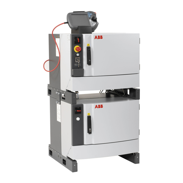
ABB OmniCore V250XT User manual

ROBOTICS
Product manual
OmniCore V250XT

Trace back information:
Workspace 22A version a10
Checked in 2022-03-02
Skribenta version 5.4.005

Product manual
OmniCore V250XT
OmniCore
Document ID: 3HAC073447-001
Revision: B
© Copyright 2020-2022 ABB. All rights reserved.
Specifications subject to change without notice.

The information in this manual is subject to change without notice and should not
be construed as a commitment by ABB. ABB assumes no responsibility for any errors
that may appear in this manual.
Except as may be expressly stated anywhere in this manual, nothing herein shall be
construed as any kind of guarantee or warranty by ABB for losses, damage to persons
or property, fitness for a specific purpose or the like.
In no event shall ABB be liable for incidental or consequential damages arising from
use of this manual and products described herein.
This manual and parts thereof must not be reproduced or copied without ABB's
written permission.
Keep for future reference.
Additional copies of this manual may be obtained from ABB.
Original instructions.
© Copyright 2020-2022 ABB. All rights reserved.
Specifications subject to change without notice.

Table of contents
9Overview of this manual ...................................................................................................................
11Product documentation ....................................................................................................................
131 Safety
131.1 Safety information .............................................................................................
131.1.1 Limitation of liability .................................................................................
141.1.2 Safety data .............................................................................................
151.1.3 Requirements on personnel ......................................................................
161.2 Safety signals and symbols .................................................................................
161.2.1 Safety signals in the manual ......................................................................
181.2.2 Safety symbols on controller labels ............................................................
201.3 Robot stopping functions ....................................................................................
201.3.1 Protective stop and emergency stop ...........................................................
221.3.2 About emergency stop .............................................................................
231.3.3 Enabling device and hold-to-run functionality ...............................................
241.4 Robot operating modes ......................................................................................
241.4.1 About the manual mode ...........................................................................
261.4.2 About the automatic mode ........................................................................
271.5 Safety during installation and commissioning .........................................................
301.6 Safety during operation ......................................................................................
311.7 Safety during maintenance and repair ...................................................................
321.8 Safety during troubleshooting ..............................................................................
331.9 Decommissioning ..............................................................................................
352 Controller description
352.1 OmniCore V250XT .............................................................................................
362.2 Technical data for OmniCore V250XT controller ......................................................
412.3 Safety functions and safety related data for OmniCore V250XT ..................................
432.4 The unit is sensitive to ESD .................................................................................
452.5 Handling of FlexPendant ....................................................................................
462.6 Network security ...............................................................................................
472.7 Open source and 3rd party components in RobotWare .............................................
482.8 ABB Ability .......................................................................................................
513 Installation and commissioning
513.1 Introduction to installation and commissioning .......................................................
523.2 Installation activities ..........................................................................................
533.3 Transporting and handling ..................................................................................
533.3.1 Lifting the controller cabinet ......................................................................
543.3.2 Unpacking .............................................................................................
553.3.3 Storing ..................................................................................................
563.4 On-site installation ............................................................................................
563.4.1 Required installation space .......................................................................
583.4.2 Securing and stacking the controller ...........................................................
593.4.3 Mounting the FlexPendant holder ...............................................................
653.5 Electrical connections ........................................................................................
653.5.1 Connectors on the OmniCore V250XT controller ...........................................
673.5.2 Connecting cables to the controller .............................................................
743.5.3 Connecting the manipulator to the controller ................................................
753.5.4 Fitting the connector for incoming mains .....................................................
773.5.5 Connecting incoming mains and protective earth to the controller ....................
803.5.6 Detaching and attaching a FlexPendant .......................................................
843.5.7 Ethernet networks on OmniCore ................................................................
923.5.8 Descriptions for connectors ......................................................................
1053.5.9 Configuring robot stopping functions ..........................................................
1093.5.10 Programmable stop functions ....................................................................
Product manual - OmniCore V250XT 5
3HAC073447-001 Revision: B
© Copyright 2020-2022 ABB. All rights reserved.
Table of contents

1123.6 I/O system .......................................................................................................
1123.6.1 Available fieldbuses .................................................................................
1143.6.2 Scalable I/O, internal and external ..............................................................
1153.7 Installing options ...............................................................................................
1153.7.1 Installing the scalable I/O devices ..............................................................
1183.7.2 Installing the safety digital base device .......................................................
1213.7.3 Installing the Ethernet extension switch .......................................................
1243.7.4 Installing the power supply optional device ..................................................
1283.7.5 Installing the fieldbus master .....................................................................
1373.7.6 Installing the conveyor tracking module (CTM) .............................................
1403.7.7 Installing the cable grommet assembly ........................................................
1463.7.8 Installing the air filter ...............................................................................
1493.7.9 Installing the mains connections cable ........................................................
1523.8 Installing external devices ...................................................................................
1533.9 Initial test before commissioning ..........................................................................
1543.10 Commissioning .................................................................................................
1554 Maintenance
1554.1 Maintenance schedule, OmniCore ........................................................................
1564.2 Inspection activities ...........................................................................................
1564.2.1 Inspection of controller .............................................................................
1574.3 Cleaning activities .............................................................................................
1574.3.1 Cleaning air filter .....................................................................................
1604.3.2 Cleaning of the controller cabinet ...............................................................
1614.3.3 Cleaning the FlexPendant .........................................................................
1634.4 Changing/replacing activities ...............................................................................
1634.4.1 Replacement of air filter ............................................................................
1664.5 Function tests ...................................................................................................
1664.5.1 Function test of emergency stop ................................................................
1674.5.2 Function test of manual, auto, and manual full speed mode with FlexPendant ....
1684.5.3 Function test of three-position enabling device .............................................
1694.5.4 Function test of Automatic Stop .................................................................
1704.5.5 Function test of General Stop ...................................................................
1714.5.6 Function test of external emergency stop ....................................................
1724.5.7 Function test of ESTOP_STATUS output .....................................................
1734.5.8 Function test of reduced speed control ........................................................
1755 Repair
1755.1 Introduction to repair .........................................................................................
1765.2 Replacement of controller parts ...........................................................................
1765.2.1 Opening the robot controller ......................................................................
1805.2.2 Replacing the fans ...................................................................................
1825.2.2.1 Replacing the standard fans ..........................................................
1865.2.2.2 Replacing the internal fan ..............................................................
1905.2.2.3 Replacing the main computer fan ...................................................
1985.2.2.4 Replacing the power unit fan .........................................................
2025.2.3 Replacing the robot signal exchange proxy ..................................................
2075.2.4 Replacing the Ethernet switch ...................................................................
2115.2.5 Replacing the connected services gateway ..................................................
2175.2.6 Replacing the scalable I/O unit ...................................................................
2225.2.7 Replacing the safety digital base device ......................................................
2265.2.8 Replacing the main computer ....................................................................
2505.2.9 Replacing the power unit ..........................................................................
2555.2.10 Replacing the power supply ......................................................................
2635.2.11 Replacing the drive unit ............................................................................
2685.2.12 Replacing the fieldbus master ....................................................................
2795.2.13 Replacing the safety module .....................................................................
2865.2.14 Replacing the main computer battery ..........................................................
2935.2.15 Replacing the conveyor tracking module (CTM) ............................................
6 Product manual - OmniCore V250XT
3HAC073447-001 Revision: B
© Copyright 2020-2022 ABB. All rights reserved.
Table of contents
2985.2.16 Replacing the air filter ..............................................................................
3025.2.17 Replacing the break resistor bleeder ...........................................................
3065.3 Replacing parts on the front panel and door ...........................................................
3065.3.1 Replacing the manipulator signal connector (SMB) ........................................
3095.3.2 Replacing the motor connector ..................................................................
3105.3.2.1 Replacing the motor connector ......................................................
3145.3.3 Replacing the HMI signal (FlexPendant) connector ........................................
3205.3.4 Replacing the cable grommet assembly ......................................................
3295.3.5 Replacing the Ethernet outlet connector with cable ........................................
3335.3.6 Replacing the LED indicator ......................................................................
3375.4 Replacing parts on the FlexPendant .....................................................................
3375.4.1 Replacing the power cable and power cable cover ........................................
3415.4.2 Replacing the joystick protection ................................................................
3445.4.3 Replacing the fasten strip .........................................................................
3456 Decommissioning
3456.1 Introduction ......................................................................................................
3466.2 Environmental information ..................................................................................
3497 Troubleshooting
3497.1 Introduction to troubleshooting ............................................................................
3517.2 Troubleshooting fault symptoms ..........................................................................
3527.2.1 No LEDs are lit on the controller .................................................................
3567.2.2 Start-up failure ........................................................................................
3607.2.3 System update failure ..............................................................................
3617.2.4 Problem releasing the robot brakes ............................................................
3647.2.5 Problem starting or connecting the FlexPendant ...........................................
3687.2.6 Problem using the joystick ........................................................................
3697.2.7 Controller fails to start ..............................................................................
3707.2.8 Reflashing firmware failure ........................................................................
3717.2.9 Inconsistent path accuracy .......................................................................
3737.2.10 Controller is overheated ...........................................................................
3747.3 Troubleshooting units ........................................................................................
3747.3.1 Troubleshooting LEDs in the controller ........................................................
3757.3.2 Troubleshooting the FlexPendant ...............................................................
3767.3.3 Troubleshooting the drive unit ...................................................................
3827.3.4 Troubleshooting the power unit ..................................................................
3897.3.5 Troubleshooting fieldbuses and I/O ............................................................
3907.3.6 Troubleshooting the connected services gateway .........................................
3967.3.7 Troubleshooting the Ethernet switch ...........................................................
3987.3.8 Troubleshooting the main computer ............................................................
4017.3.9 Troubleshooting the process power supply ..................................................
4037.3.10 Troubleshooting the power supply, ODVA ....................................................
4057.3.11 Troubleshooting the robot signal exchange proxy .........................................
4118 Reference information
4118.1 Introduction ......................................................................................................
4128.2 Applicable standards .........................................................................................
4138.3 Unit conversion .................................................................................................
4148.4 Standard toolkit for controller ..............................................................................
4158.5 Screw joints .....................................................................................................
4168.6 Weight specifications .........................................................................................
4178.7 Lifting accessories and lifting instructions ..............................................................
4199 Spare parts
4209.1 Controller parts .................................................................................................
4219.1.1 Controller system parts ............................................................................
4269.1.2 Mains connection parts ............................................................................
Product manual - OmniCore V250XT 7
3HAC073447-001 Revision: B
© Copyright 2020-2022 ABB. All rights reserved.
Table of contents

4279.1.3 Logic parts .............................................................................................
4319.1.4 Application parts .....................................................................................
4369.1.5 Cabinet parts ..........................................................................................
4429.1.6 Miscellaneous parts .................................................................................
4449.1.7 Cables ..................................................................................................
4469.2 FlexPendant parts .............................................................................................
4479.3 Manipulator cables ............................................................................................
4479.3.1 Manipulator cables ..................................................................................
4489.3.2 Customer cables - CP/CS connectors (option) ..............................................
4499.3.3 Customer cables - Ethernet floor cables ......................................................
4509.3.4 Customer cables - DeviceNet cables ...........................................................
451Index
8 Product manual - OmniCore V250XT
3HAC073447-001 Revision: B
© Copyright 2020-2022 ABB. All rights reserved.
Table of contents

Overview of this manual
About this manual
This manual contains instructions for:
• mechanical and electrical installation of the controller
• maintenance of the controller
• mechanical and electrical repair of the controller
Usage
This manual should be used during:
• installation and commissioning, from lifting the product to its work site and
securing it to the foundation, to making it ready for operation
• maintenance work
• repair work
• decommissioning work
Note
It is the responsibility of the integrator to conduct a risk assessment of the final
application.
It is the responsibility of the integrator to provide safety and user guides for the
robot system.
Who should read this manual?
This manual is intended for:
• installation personnel
• maintenance personnel
• repair personnel.
Prerequisites
A maintenance/repair/installation craftsman working with an ABB robot must:
• be trained by ABB and have the required knowledge of mechanical and
electrical installation/repair/maintenance work.
• be trained to respond to emergencies or abnormal situations.
Product manual scope
The manual covers all variants and designs of the OmniCore V250XT. Some variants
and designs may have been removed from the business offer and are no longer
available for purchase.
References
Document IDDocument name
3HAC065034-001Product specification - OmniCore C line
3HAC074000-008Circuit diagram - OmniCore V250XT
Continues on next page
Product manual - OmniCore V250XT 9
3HAC073447-001 Revision: B
© Copyright 2020-2022 ABB. All rights reserved.
Overview of this manual

Document IDDocument name
3HAC032104-001Operating manual - RobotStudio
3HAC065036-001Operating manual - OmniCore
3HAC065037-001Operating manual - Integrator's guide OmniCore
3HAC065041-001Technical reference manual - System parameters
3HAC066559-001Application manual - Functional safety and SafeMove
3HAC028879-001Application manual - Connected Services
3HAC066561-001Application manual - Conveyor tracking
3HAC031045-001Safety manual for robot - Manipulator and IRC5 or OmniCore con-
troller
Revisions
DescriptionRevision
First edition.A
Published in release 22A. The following updates are made in this revision:
• Added information on decoupling ES output and ES input, see De-
scriptions for connectors on page 92, and Configuring robot stopping
functions on page 105.
•NOTE about protected earth harness removed from sections Residual
current on page 40 and Connection of protective earth on page 78.
• Part numbers for mating connectors corrected in Robot signal ex-
change proxy mating connectors on page 92.
• Minor corrections in section Replacing the break resistor bleeder on
page 302.
• Minor corrections in section Installing the air filter on page 146.
• Information about I/O Network added in section Firewall settings on
page 91.
B
10 Product manual - OmniCore V250XT
3HAC073447-001 Revision: B
© Copyright 2020-2022 ABB. All rights reserved.
Overview of this manual
Continued

Product documentation
Categories for user documentation from ABB Robotics
The user documentation from ABB Robotics is divided into a number of categories.
This listing is based on the type of information in the documents, regardless of
whether the products are standard or optional.
Tip
All documents can be found via myABB Business Portal, www.abb.com/myABB.
Product manuals
Manipulators, controllers, DressPack/SpotPack, and most other hardware is
delivered with a Product manual that generally contains:
• Safety information.
• Installation and commissioning (descriptions of mechanical installation or
electrical connections).
•Maintenance (descriptions of all required preventive maintenance procedures
including intervals and expected life time of parts).
• Repair (descriptions of all recommended repair procedures including spare
parts).
• Calibration.
• Decommissioning.
•Reference information (safety standards, unit conversions, screw joints, lists
of tools).
• Spare parts list with corresponding figures (or references to separate spare
parts lists).
• References to circuit diagrams.
Technical reference manuals
The technical reference manuals describe reference information for robotics
products, for example lubrication, the RAPID language, and system parameters.
Application manuals
Specific applications (for example software or hardware options) are described in
Application manuals. An application manual can describe one or several
applications.
An application manual generally contains information about:
• The purpose of the application (what it does and when it is useful).
•What is included (for example cables, I/O boards, RAPID instructions, system
parameters, software).
• How to install included or required hardware.
• How to use the application.
• Examples of how to use the application.
Continues on next page
Product manual - OmniCore V250XT 11
3HAC073447-001 Revision: B
© Copyright 2020-2022 ABB. All rights reserved.
Product documentation

Operating manuals
The operating manuals describe hands-on handling of the products. The manuals
are aimed at those having first-hand operational contact with the product, that is
production cell operators, programmers, and troubleshooters.
12 Product manual - OmniCore V250XT
3HAC073447-001 Revision: B
© Copyright 2020-2022 ABB. All rights reserved.
Product documentation
Continued

1 Safety
1.1 Safety information
1.1.1 Limitation of liability
Limitation of liability
Any information given in this manual regarding safety must not be construed as a
warranty by ABB that the industrial robot will not cause injury or damage even if
all safety instructions are complied with.
The information does not cover how to design, install and operate a robot system,
nor does it cover all peripheral equipment that can influence the safety of the robot
system.
In particular, liability cannot be accepted if injury or damage has been caused for
any of the following reasons:
• Use of the robot in other ways than intended.
• Incorrect operation or maintenance.
• Operation of the robot when the safety devices are defective, not in their
intended location or in any other way not working.
• When instructions for operation and maintenance are not followed.
• Non-authorized design modifications of the robot.
• Repairs on the robot and its spare parts carried out by in-experienced or
non-qualified personnel.
• Foreign objects.
• Force majeure.
Spare parts and equipment
ABB supplies original spare parts and equipment which have been tested and
approved. The installation and/or use of non-original spare parts and equipment
can negatively affect the safety, function, performance, and structural properties
of the robot. ABB is not liable for damages caused by the use of non-original spare
parts and equipment.
Product manual - OmniCore V250XT 13
3HAC073447-001 Revision: B
© Copyright 2020-2022 ABB. All rights reserved.
1 Safety
1.1.1 Limitation of liability

1.1.2 Safety data
Prevailing standards and directives
For the use of industrial robots, regulations must be fulfilled as described in the
following standards and directives:
• EN ISO 10218-1:2011
• Machinery Directive 2006/42/EC
Performance level and category
EN ISO 10218-1 requires structure category 3 and performance level PL d on the
robot, see EN ISO 13849-1.
Risk assessment
The results of a risk assessment performed on the robot and its intended application
may determine that a safety-related control system performance other than that
stated in ISO 10218 is warranted for the application.
The SISTEMA/ABB FSDT libraries contains details for the safety functions.
Note
The safety functions are divided into two types called Basic Safety Functions
and Extended Safety Functions.
Performance level data
The performance level data for the respective controller variant is presented in
section Safety functions and safety related data for OmniCore V250XT on page 41.
14 Product manual - OmniCore V250XT
3HAC073447-001 Revision: B
© Copyright 2020-2022 ABB. All rights reserved.
1 Safety
1.1.2 Safety data

1.1.3 Requirements on personnel
General
Only personnel with appropriate training are allowed to install, maintain, service,
repair, and use the robot. This includes electrical, mechanical, hydraulics,
pneumatics, and other hazards identified in the risk assessment.
Persons who are under the influence of alcohol, drugs or any other intoxicating
substances are not allowed to install, maintain, service, repair, or use the robot.
The plant liable must make sure that the personnel is trained on the robot, and on
responding to emergency or abnormal situations.
Personal protective equipment
Use personal protective equipment, as stated in the instructions.
Product manual - OmniCore V250XT 15
3HAC073447-001 Revision: B
© Copyright 2020-2022 ABB. All rights reserved.
1 Safety
1.1.3 Requirements on personnel

1.2 Safety signals and symbols
1.2.1 Safety signals in the manual
Introduction to safety signals
This section specifies all safety signals used in the user manuals. Each signal
consists of:
• A caption specifying the hazard level (DANGER, WARNING, or CAUTION)
and the type of hazard.
• Instruction about how to reduce the hazard to an acceptable level.
• A brief description of remaining hazards, if not adequately reduced.
Hazard levels
The table below defines the captions specifying the hazard levels used throughout
this manual.
SignificanceDesignationSymbol
Signal word used to indicate an imminently hazard-
ous situation which, if not avoided, will result in ser-
ious injury.
DANGER
Signal word used to indicate a potentially hazardous
situation which, if not avoided, could result in serious
injury.
WARNING
Signal word used to indicate a potentially hazardous
situation related to electrical hazards which, if not
avoided, could result in serious injury.
ELECTRICAL
SHOCK
Signal word used to indicate a potentially hazardous
situation which, if not avoided, could result in slight
injury.
CAUTION
Signal word used to indicate a potentially hazardous
situation which, if not avoided, could result in severe
damage to the product.
ELECTROSTATIC
DISCHARGE (ESD)
Signal word used to indicate important facts and
conditions.
NOTE
Continues on next page
16 Product manual - OmniCore V250XT
3HAC073447-001 Revision: B
© Copyright 2020-2022 ABB. All rights reserved.
1 Safety
1.2.1 Safety signals in the manual

SignificanceDesignationSymbol
Signal word used to indicate where to find additional
information or how to do an operation in an easier
way.
TIP
Product manual - OmniCore V250XT 17
3HAC073447-001 Revision: B
© Copyright 2020-2022 ABB. All rights reserved.
1 Safety
1.2.1 Safety signals in the manual
Continued

1.2.2 Safety symbols on controller labels
Introduction to safety symbols
Both the manipulator and the controller are marked with labels containing safety
symbols and important information about the product. The purpose of the labels
is to ensure personal safety for all personnel handling the robot, for example during
installation, service, or operation.
The safety symbols are language independent, they only use graphics. The
information labels contain information in text. See Symbols and information on
labels on page 18.
Note
The safety and information labels on the product must be observed.
Symbols and information on labels
Note
The descriptions in this section are generic, the labels can contain additional
information such as values.
DescriptionLabel
Read the user manual before use.
xx1400001152
CE label
xx1800000835
Continues on next page
18 Product manual - OmniCore V250XT
3HAC073447-001 Revision: B
© Copyright 2020-2022 ABB. All rights reserved.
1 Safety
1.2.2 Safety symbols on controller labels

DescriptionLabel
SafeMove label (for SafeMove Basic and SafeMove Pro soft-
ware).
xx1700000355
Rating label (example)
xx1900001805
Electrical shock
xx1400001151
Warning & caution label
Riskofelectricalshock.
Keepcontrollercoverclosedwhenpowerison.
Keepawayfrominsidefor3minutesafterturningoff
poweranddisconnectingcable.
Readoperationmanualbeforeinstallation.
Enclosureenvironmentaltyperatingistype1.
Insertingfingersor foreignobjectsintoopening
maycausepersonalinjury.
xx1800000836
High voltage inside the module even if the main switch is in
the OFF position.
xx1400001156
ESD sensitive components inside the controller.
xx1400001162
Product manual - OmniCore V250XT 19
3HAC073447-001 Revision: B
© Copyright 2020-2022 ABB. All rights reserved.
1 Safety
1.2.2 Safety symbols on controller labels
Continued

1.3 Robot stopping functions
1.3.1 Protective stop and emergency stop
Robot stopping functions
The robot has protective and emergency stop functions (stop category 0 or 1, in
accordance with IEC 60204-1).
As defined in IEC 60204-1, stopping by immediate removal of
power to the machine actuators.
Stop category 0
As defined in IEC 60204-1, a controlled stop with power avail-
able to the machine actuators to achieve the stop and then re-
moval of power when the stop is achieved.
Stop category 1
A stop function, protective or emergency stop, has a default setting for the stop
category, see Inputs to initiate a protective stop or an emergency stop on page 20.
The default stop category for a protective or emergency stop can be re-configured.
Activation of external safety rated devices, connected to the robot controller through
dedicated discrete safety inputs or safety protocols, will initiate these stop functions.
Inputs to initiate a protective stop or an emergency stop
Stop category recon-
figurable Y/N
Default stop categoryDescriptionInputs to initiate a
stop function
YStop category 0Input to initiate the
emergency stop func-
tion. The Emergency
Stop function is initi-
ated in both automatic
and manual mode.
Emergency Stop (ES)
For deviations, see
the product manual
for the manipulator.
YStop category 1Input to initiate the
protective stop func-
tion. The protective
stop function can
either be configured
as Automatic Stop
(AS) or General Stop
(GS). Automatic
Stop(AS) is only initi-
ated in automatic
mode. General
Stop(GS) is initiated
in both manual mode
and automatic mode.
Automatic Stop
(AS)/General Stop
(GS)
Note
The default configuration for the protective stop function triggered by the
protective stop input is Automatic Stop.
For example, a safety rated output from a presence sensing device, connected to
AS / GS, a dedicated discrete protective stop input on the robot controller, will
when the protective stop function is configured as Automatic Stop (AS) initiate the
protective stop function in automatic mode only.
Continues on next page
20 Product manual - OmniCore V250XT
3HAC073447-001 Revision: B
© Copyright 2020-2022 ABB. All rights reserved.
1 Safety
1.3.1 Protective stop and emergency stop
Table of contents
Other ABB Robotics manuals

ABB
ABB IRB 6620 Guide

ABB
ABB Scalable I/O Instructions for use

ABB
ABB IRB1410 User manual

ABB
ABB DressPack IRB 6620 User manual

ABB
ABB IRB 660 User manual

ABB
ABB DressPack IRB6650S User manual

ABB
ABB IRB 140 User manual

ABB
ABB IRB 360-1/800 User manual

ABB
ABB FlexTrack IRT501 Series User manual

ABB
ABB IRB 8700 Owner's manual