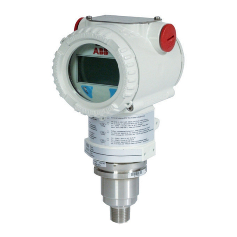
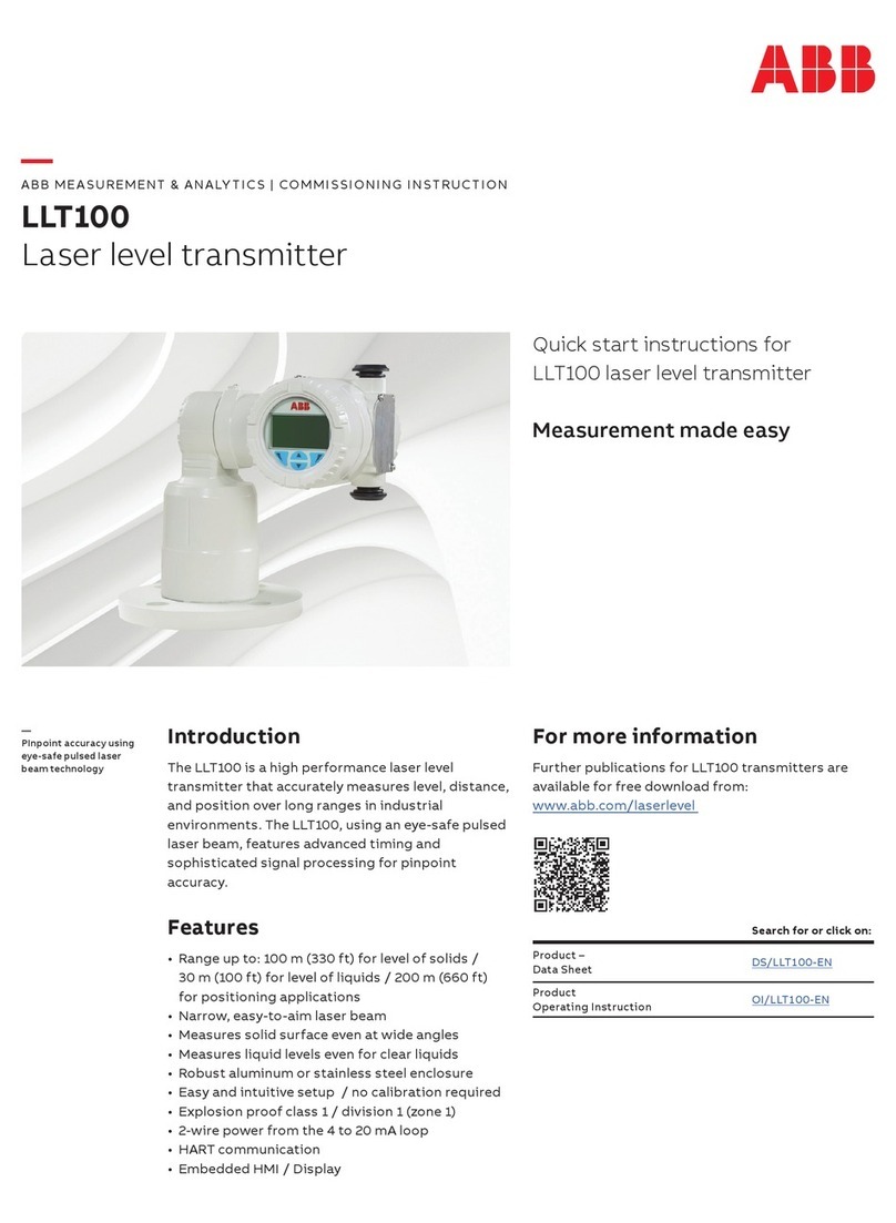
ABB TTF300 User manual

—
ABB MEASUREMENT & ANALYTICS |
COMMISSIONING INSTRUCTION | CI/TTF300-EN REV. H
TTF300
Field
-mount temperature transmitter
—
ABB Measurement & Analytics
For your local ABB contact, visit:
www.abb.com/contacts
For more
product information, visit:
www.abb.com/temperature
Temperature transmitter for all
communications protocols.
Redundancy thanks to two inputs.
Measurement made easy
CI/TTF300
-EN Rev. H 09.2022
—
TTF300
Introduction
The TTF300 is available with the HART,
PROFIBUS
PA and FOUNDATION Fieldbus
communication protocols.
The TTF300 has
global approvals for explosion
protection up to Zone
0.
The TTF300 implements various NAMUR
recommendations, including
NE 89 and NE 107.
Safety
-relevant applications up to SIL 3
(redundant) are supported in accordance with
IEC
61508.
Additional Info
rmation
Additional documentation on
TTF300 is available for
download free of charge at
www.abb.com/
temperature.
Alternatively simply scan this code:
—
We reserve the right to make technical changes or modify the contents of this document
without prior notice. With regard to purchase orders, the agreed particulars shall prevail.
ABB does not accept any responsibility whatsoever for potential errors or po
ssible lack of
information in this document.
We reserve all rights in this document and in the subject matter and illustrations contained
therein. Any reproduction, disclosure to th ird parties or utilization of its contents
– in whole
or in parts
– is forbidden without prior written consent of ABB.
© ABB 2022 3KXT221001R4401

2 TTF300 FIELD-MOUNT TEMPERATURE TRANSMITTER | CI/TTF300-EN REV. H
Table of contents
1Safety ........................................................................4
General information and instructions ............................... 4
Warnings............................................................................... 4
Intended use......................................................................... 5
Improper use ........................................................................ 5
Cyber security disclaimer.................................................... 5
Software downloads............................................................ 5
Manufacturer’s address ...................................................... 5
Customer service center ..................................................... 5
2Use in potentially explosive atmospheres in
accordance with ATEX and IECEx............................6
Ex marking............................................................................ 6
Transmitter...................................................................... 6
LCD indicator....................................................................7
Temperature data................................................................ 8
Transmitter...................................................................... 8
LCD indicator................................................................... 8
Electrical data....................................................................... 8
Transmitter...................................................................... 8
LCD indicator................................................................... 9
Installation instructions.....................................................10
ATEX / IECEx / EAC-Ex...................................................10
Cable entries...................................................................10
Electrical connections.................................................... 11
Commissioning...................................................................16
Operating instructions....................................................... 17
Damage to the ‘Flameproof (enclosure)– Ex d’ type of
protection ....................................................................... 17
Protection against electrostatic discharges............... 17
Repair ................................................................................... 17
3Use in potentially explosive atmospheres in
accordance with FM and CSA.................................18
Ex marking...........................................................................18
Transmitter.....................................................................18
LCD indicator..................................................................19
Installation instructions .................................................... 20
FM / CSA......................................................................... 20
Electrical connections................................................... 20
Commissioning................................................................... 21
Operating instructions....................................................... 21
Adverse effect on the ‘Explosionproof – XP’ type of
protection ....................................................................... 21
Protection against electrostatic discharges............... 21
Repair ................................................................................... 21
4Product identification ........................................... 22
Name plate ..........................................................................22
Explosion protection marking for devices with one
type of protection..........................................................22
Explosion protection marking for devices with several
types of protection ........................................................23
5Transport and storage...........................................24
Inspection............................................................................24
Transporting the device.....................................................24
Storing the device...............................................................24
Ambient conditions........................................................24
Returning devices ...............................................................24
6Installation .............................................................. 25
Ambient conditions ............................................................25
Mounting .............................................................................25
Opening and closing the housing .....................................26
Rotating the LCD indicator................................................26
7Electrical connections............................................ 27
Safety instructions .............................................................27
Protection of the transmitter from damage caused by
highly energetic electrical interferences ..........................27
Suitable protective measures.......................................28
Conductor material ............................................................28
Power supply cable ........................................................28
Cable glands........................................................................28
Shielding of the sensor connecting cable ........................29
Recommended shielding / grounding .........................29
Additional examples for shielding / grounding ......... 30
Terminal assignment..........................................................32
Resistance thermometers (RTD) / resistors
(potentiometer) .............................................................32
Thermocouples / voltages and resistance
thermometers (RTD) / thermocouple combinations .33
Terminal for sensor connection cable ..............................34
Electrical data for inputs and outputs..............................35
Input - resistance thermometer / resistances............35
Input - thermocouples / voltages.................................35
Functionality input.........................................................35
Output – HART®..............................................................36
Output – PROFIBUS PA® ................................................36
Output – FOUNDATION Fieldbus®................................37
Power supply ..................................................................37
Power supply – HART® ...................................................37
Power supply – PROFIBUS / FOUNDATION Fieldbus ..38
TTF300 FIELD-MOUNT TEMPERATURE TRANSMITTER | CI/TTF300-EN REV. H 3
8Commissioning .......................................................39
General................................................................................ 39
Checks prior to commissioning........................................ 39
Communication.................................................................. 39
HART® Communication................................................. 39
PROFIBUS® Communication......................................... 40
FOUNDATION Fieldbus® Communication....................41
Basic Setup..........................................................................41
9Operation ................................................................42
Safety instructions ............................................................ 42
Hardware settings ............................................................. 42
Menu navigation................................................................. 42
10 Maintenance............................................................43
Safety instructions ............................................................ 43
11 Recycling and disposal...........................................43
12 Specification ...........................................................43
13 Additional documents............................................43
14 Appendix ................................................................ 44
Return form ........................................................................ 44

4 TTF300 FIELD-MOUNT TEMPERATURE TRANSMITTER | CI/TTF300-EN REV. H
1Safety
General information and instructions
These instructions are an important part of the product and
must be retained for future reference.
Installation, commissioning, and maintenance of the product
may only be performed by trained specialist personnel who have
been authorized by the plant operator accordingly. The specialist
personnel must have read and understood the manual and must
comply with its instructions.
For additional information or if specific problems occur that are
not discussed in these instructions, contact the manufacturer.
The content of these instructions is neither part of nor an
amendment to any previous or existing agreement, promise or
legal relationship.
Modifications and repairs to the product may only be performed
if expressly permitted by these instructions.
Information and symbols on the product must be observed.
These may not be removed and must be fully legible at all times.
The operating company must strictly observe the applicable
national regulations relating to the installation, function testing,
repair and maintenance of electrical products.
Warnings
The warnings in these instructions are structured as follows:
DANGER
The signal word ‘DANGER’ indicates an imminent danger.
Failure to observe this information will result in death or
severe injury.
WARNING
The signal word ‘WARNING’ indicates an imminent danger.
Failure to observe this information may result in death or
severe injury.
CAUTION
The signal word ‘CAUTION’ indicates an imminent danger.
Failure to observe this information may result in minor or
moderate injury.
NOTICE
The signal word
‘NOTICE’
indicates possible material damage.
Note
‘Note’ indicates useful or important information about the
product.

TTF300 FIELD-MOUNT TEMPERATURE TRANSMITTER | CI/TTF300-EN REV. H 5
Intended use
This device is intended for the following uses:
• To measure the temperature of fluid, pulpy or pasty
substances and gases or resistance/voltage values.
The device has been designed for use exclusively within the
technical limit values indicated on the name plate and in the data
sheets.
• The maximum ambient temperature must not be exceeded.
• The IP rating of the housing must be observed during
operation.
• For use in potentially explosive atmospheres, follow the
associated guidelines.
• When using as a SIL-device in safety-relevant applications,
the corresponding SIL-Safety Manual should be observed.
Improper use
The following are considered to be instances of especially
improper use of the device:
• For use as a climbing aid, for example for mounting
purposes.
• For use as a bracket for external loads, for example as a
support for piping, etc.
• Material application, for example by painting over the
housing, name plate or welding/soldering on parts.
• Material removal, for example by spot drilling the
housing.
Cyber security disclaimer
This product is designed to be connected to and to
communicate information and data via a network interface. It is
operator’s sole responsibility to provide and continuously ensure
a secure connection between the product and your network or
any other network (as the case may be).
Operator shall establish and maintain any appropriate measures
(such as but not limited to the installation of firewalls,
application of authentication measures, encryption of data,
installation of anti-virus programs, etc.) to protect the product,
the network, its system and the interface against any kind of
security breaches, unauthorized access, interference, intrusion,
leakage and/or theft of data or information.
ABB and its affiliates are not liable for damages and/or losses
related to such security breaches, any unauthorized access,
interference, intrusion, leakage and/or theft of data or
information.
Software downloads
By visiting the web pages indicated below, you will find
notifications about newly found software vulnerabilities and
options to download the latest software. It is recommended that
you visit this web pages regularly:
www.abb.com/cybersecurity
ABB Library – TTF300 – Software downloads
Manufacturer’s address
ABB AG
Measurement & Analytics
Schillerstr. 72
32425 Minden
Germany
Tel: +49 571 830-0
Fax: +49 571 830-1806
Customer service center
Tel: +49 180 5 222 580
Email: automation.service@de.abb.com

6 TTF300 FIELD-MOUNT TEMPERATURE TRANSMITTER | CI/TTF300-EN REV. H
2Use in potentially explosive atmospheres in accordance with ATEX and IECEx
Ex marking
Note
• Further information on the approval of devices for use in potentially explosive atmospheres can be found in the explosion
protection test certificates (at www.abb.com/temperature).
• Depending on the design, a specific marking in accordance with ATEX or IECEx applies.
• A list of standards, including the output data to which the device conforms, can be found in the examination certificate or
manufacturer’s declaration supplied with the device.
• In devices with several types of protection, for example TTF300 -E4, observe the ‘Product Identification’ chapter in the operating
or commissioning instruction before commissioning.
Transmitter
ATEX intrinsic safety
The device fulfills the requirements of Directive 2014/34/EU in
case of corresponding purchase orders and is approved for use
in Zone 0, 1 and 2.
Model TTF300-E1H
To HW rev.
01.07:
Type Examination Test Certificate
From HW rev.
02.00:
Type Examination Test Certificate
PTB 05 ATEX 2017 X
PTB 20 ATEX 2008 X
Model TTF300-E1P and TTF300-E1F
Type
Examination Test Certificate
PTB 09 ATEX 2016 X
II 1 G
Ex ia IIC T6…T1 Ga
II 2 (1) G
Ex [ia IIC Ga] ib IIC T6…T1 Gb
II 2 G (1D)
Ex [ia IIIC Da] ib IIC T6…T1 Gb
ATEX increased safety and dust explosion protection
Approved for use in zone 2 and 22.
Model TTF300-E5
TTF300-E5H to HW rev. 01.07, TTF300-E5P, TTF300-E5F:
Manufacturer’s Declaration
II 3 G
Ex ec IIC T6...T1 Gc
II 3 D
Ex tc IIIB T133°C Dc
ATEX dust explosion protection
Approved for use in Zone 21 and 22.
TTF300-D5H model to HW rev. 01.07
Type Examination Test Certificate
BVS 06 ATEX E 029
II 2D
Ex tb IIIC T135°C Db
II 3D
Ex tc IIIC T135°C Dc
ATEX dust explosion protection | intrinsic safety
Permitted for zone 21, 22 | Zone 0, 1 and 2.
The ‘D6H’ coding combines ‘Dust explosion protection’ (TTF300-
D5H) and ‘Intrinsic safety’ (TTF300-E1H) types of protection.
Devices with several types of protection may only be operated in
one of the possible types of protection. For this purpose,
observe the ‘Product Identification’ chapter in the operating or
commissioning instruction before commissioning.
TTF300-D6H model to HW rev. 01.07
Type examination test certificate
“Dust explosion protection”, (TTF300-D5H)
BVS 06 ATEX E 029
Type examination certificate
“Intrinsic safety”, (TTF300-E1H)
PTB 05 ATEX 2017 X
II 1G
Ex ia IIC T6…T1 Ga
II 2D Ex tb IIIC T135°C Db
ATEX flameproof (enclosure)
Approved for use in Zone 1 and 2.
Model TTF300-E3
Type Examination Test
Certificate
PTB 99 ATEX 1144 X
II 1/2 G
Ex db IIC T6/T4 Ga/Gb

TTF300 FIELD-MOUNT TEMPERATURE TRANSMITTER | CI/TTF300-EN REV. H 7
ATEX flameproof (enclosure) | intrinsic safety
Permitted for zone 1 and 2 (flameproof enclosure) | Zone 0, 1 and
2 (intrinsic safety).
The ‘E4’ coding combines the following types of protection:
‘Intrinsic safety’ (TTF300-E1) and ‘Flameproof (enclosure)’
(TTF300-E3).
Devices with several types of protection may only be operated in
one of the possible types of protection. For this purpose,
observe the ‘Product Identification’ chapter in the operating or
commissioning instruction before commissioning.
Model TTF300-E4
Type Examination Test Certificate
PTB 99 ATEX 1144 X
TTF300
-E4P and TTF300-E4F:
Type Examination Test Certificate
PTB 05 ATEX 2016 X
TTF300
-E4H to HW rev. 01.07:
Type Examination Test Certificate
PTB 05 ATEX 2017 X
TTF300
-E4H from HW rev. 02.00:
Type Examination Test Certificate
PTB 20 ATEX 2008 X
II 1/2 G
Ex db IIC T6/T4 Ga/Gb
II 1 G Ex ia IIC T6…T1 Ga
IECEx intrinsic safety
Approved for use in Zone 0, 1, and 2.
Model TTF300-H1H
To HW rev.
01.07:
IECEx Certificate of Conformity
From HW rev.
02.00:
IECEx certificate of conformity
IECEx PTB 09.0014X
IECEx PTB 20.0035X
Model TTF300-H1P and TTF300-H1F
IECEx Certificate of Conformity
IECEx PTB 11.0108X
Ex ia IIC T6...T1 Ga
Ex [ia IIC Ga] ib IIC T6...T1 Gb
Ex [ia IIIC Da] ib IIC T6...T1 Gb
IECEx dust explosion protection
Approved for use in Zone 21 and 22.
TTF300
-J5H model to HW rev. 01.07
IECEx certificate of conformity
IECEx BVS 17.0065X
Ex tb IIIC T135°C Db
Ex tc IIIC T135°C Dc
IECEx flameproof (enclosure)
Approved for use in Zone 1 and 2.
Model TTF300-H5
IECEx Certificate of Conformity
IECEx PTB 12.0039 X
Ex db IIC T6/T4 Gb
LCD indicator
ATEX intrinsic safety
The device fulfills the requirements of Directive 2014/34/EU in
case of corresponding purchase orders and is approved for use
in Zone 0, 1 and 2.
Type Examination Test
Certificate
PTB 05 ATEX 2079 X
II 1G Ex ia IIC T6…T1 Ga
IECEx intrinsic safety
Approved for use in Zone 0, 1, and 2.
IECEx certificate of conformity
IECEx PTB 12.0028X
Ex ia IIC T6…T1 Ga

8 TTF300 FIELD-MOUNT TEMPERATURE TRANSMITTER | CI/TTF300-EN REV. H
… 2 Use in potentially explosive atmospheres in accordance with ATEX and IECEx
Temperature data
Transmitter
ATEX / IECEx intrinsic safety, ATEX increased safety as well
as dust explosion protection (Zone 22)
Temperature class
Permissible ambient temperature range
T6, T5
−50 to 56
°C
(−58 to 132.8 °F)
T4 to T1
−50 to 85
°C
(−58 to 185.0
°F)
ATEX / IECEx flameproof (enclosure)
Temperature class
Permissible ambient temperature range on the
connection head
T6
−40 to 67
°C
(−40 to 152 °F)
T4 to T1
−40 to 85
°C
(−40 to 185 °F)
LCD indicator
ATEX / IECEx intrinsic safety
Temperature class
Permissible ambient temperature range
T6
−50 to 56
°C
(−58 to 132.8
°F)
T4 to T1
−50 to 85
°C
(−58 to 185 °F)
Electrical data
Transmitter
Intrinsic safety type of protection Ex ia IIC (Part 1)
Supply circuit
TTF300-
E1H
TTF300-
H1H
TTF300-E1P/-
H1P
TTF300-E1F/-
H1F
FISCO*
ENTITY
Max. voltage
Ui= 30 V
Ui≤ 17.5 V
Ui≤ 24.0 V
Short-circuit current
Ii= 130 mA
Ii≤ 183 mA*
Ii≤ 250 mA
Max. power
Pi= 0.8 W
Pi≤ 2.56 W*
Pi≤ 1.2 W
Internal inductance
L
i
= 160 μH**
L
i
≤ 10 μH
L
i
≤ 10 μH
Internal capacitance
Ci= 0.57 nF***
Ci≤ 5 nF
Ci≤ 5 nF
*II B FISCO: Ii≤ 380 mA, Pi≤ 5.32 W
** Only applies to HART variant. From hardware rev. 02.00, previously 0.5 mH
*** Only applies for HART variants. From hardware rev. 1.07, previously 5 nF
Intrinsic safety type of protection Ex ia IIC (Part 2)
TTF300
-E1H, TTF300-H1H measurement current circuit model
Resistance
thermometers, resistors
Thermocouples, voltages
Max. voltage
Uo= 6.5 V
Uo= 1.2 V
Short-circuit current
Io= 17.8 mA1
Io= 50 mA
Max. power
Po= 29 mW2
Po= 60 mW
Internal inductance
Li
≈ 0 mH
(negligible)
Li
≈ 0 mH
(negligible)
Internal capacitance
Ci= 49 nF
Ci= 49 nF
Maximum permissible
external inductance
Lo
= 5 mH
Lo
= 5 mH
Maximum permissible
external capacitance
Co= 1.65 μF
3
Co= 1.15 μF
4
1 From Hardware rev. 02.00, previously 25 mA
2 From Hardware rev. 02.00, previously 38 mW
3 From Hardware rev. 02.00, previously 1.55 μF
4 From Hardware rev. 02.00, previously 1.05 μF

TTF300 FIELD-MOUNT TEMPERATURE TRANSMITTER | CI/TTF300-EN REV. H 9
Intrinsic safety type of protection Ex ia IIC (Part 2)
TTF300
-E1P, TTF300-H1P, TTF300-E1F, TTF300-H1F measurement current
circuit model
Resistance
thermometers,
resistors
Thermocouples, voltages
Max. voltage
U
o
= 6.5 V
U
o
= 1.2 V
Short
-circuit current I
o
= 25 mA
I
o
= 50 mA
Max. power
P
o
= 38 mW
P
o
= 60 mW
Internal inductance
Li≈ 0 mH (negligible)
Internal capacitance
C
i
= 49 nF
C
i
= 49 nF
Maximum permissible
external inductance
Lo
= 5 mH
Lo
= 5 mH
Maximum permissible
external capacitance
Co
= 1.55 μF
Co
= 1.05 μF
Intrinsic safety type of protection Ex ia IIC (Part 3)
LCD indicator interface
Max. voltage
U
o
= 6.2 V
Short-circuit current
Io= 65.2 mA
Max. power
P
o
= 101 mW
Internal inductance
Li≈ 0 mH (negligible)
Internal capacitance
C
i
≈ 0 nF (negligible)
Maximum permissible external
inductance
Lo
= 5 mH
Maximum permissible external
capacitance
Co
= 1.4 μF
Type of protection: flameproof (enclosure) Ex db IIC
Supply circuit
Maximum voltage
US= 30 V
Maximum current
Is= 32
mA, limited by the
upstream
fuse
(rated fuse current 32
mA)
Measurement current circuit
Maximum voltage
UO= 6.5 V
Maximum current
I
O
= 17.8
mA
Maximum power
PO= 39 mW
Type of protection: dust explosion protection
Ex tb IIIC T135°C Db, Ex tc IIIC T135°C Dc
Non-intrinsically safe power supply
Supply circuit
Maximum voltage
U
S
= 30 V
Maximum current
Is= 32
mA, limited by the
upstream
fuse
(rated fuse current 32
mA)
Measurement current circuit
Maximum
permissible power
dissipation in the measuring inset
(sensor)
Pi
= 0.5 W
Intrinsically safe power supply
If in the dust explosion protection type of protection, the
transmitter is supplied with power from a power supply unit
which is designed as intrinsically safe in the ‘Ex ia’ or ‘Ex ib’ type
of protection, a limitation of the power supply circuit by an
upstream fuse is not required.
In this case, the electric data of the transmitter for the intrinsic
safety type of protection Ex ia IIC (Part 1) for TTF300-E1H and
TTF300-H1H, Ex ia IIC (Part 2) as well Ex ia IIC (Part 3) should be
complied with.
Refer to Intrinsic safety type of protection Ex ia IIC (Part 1) on
page 8.
LCD indicator
Intrinsic safety type of protection Ex ia IIC
Supply circuit
Max. voltage
Ui= 9 V
Short
-circuit current I
i
= 65.2 mA
Max. power
Pi= 101 mW
Internal inductance
L
i
≈ 0 mH (negligible)
Internal capacitance
Ci≈ 0 nF (negligible)

10 TTF300 FIELD-MOUNT TEMPERATURE TRANSMITTER | CI/TTF300-EN REV. H
… 2 Use in potentially explosive atmospheres in accordance with ATEX and IECEx
Installation instructions
ATEX / IECEx / EAC-Ex
The installation, commissioning, maintenance and repair of
devices in potentially explosive atmospheres must only be
carried out by appropriately trained personnel. Works may be
carried out only by persons, whose training has included
instructions on different types of protection and installation
techniques, concerned rules and regulations as well as general
principles of zoning. The person must possess the appropriate
competences for the type of work to be conducted.
When operating with combustible dusts, comply with
EN 60079-31.
The safety instructions for electrical apparatus in potentially
explosive areas must be in accordance with Directive
2014/34/EU (ATEX) and IEC 60079-14 (Installation of electrical
equipment in potentially explosive areas).
Comply with the applicable regulations for the protection of
employees to ensure safe operation.
Cable entries
Devices with type of protection ‘Ex d’ without supplied cable
glands
For devices with the ‘Ex d – flameproof (enclosure)’ type of
protection which are supplied without cable glands, observe the
instructions in Flameproof (enclosure) – Zone 1 on page 15.
For information on the cable gland used, refer to the relevant
data sheet and operating instructions.
Devices with type of protection ‘Ex d’ with cable glands
If devices in ‘Ex d – flameproof (enclosure)’ type of protection
with cable gland are ordered, an Ex d certified cable gland is
factory-installed.
Cable gland data
• Thread: 2 × M20 × 1.5 or 2 × ½ in NPT
• Temperature range: −50 to 85 °C (−58 to 185 °F)
• External cable diameter: 3.2 to 8.7 mm (0.13 to 0.34 in)
• Material: Brass, nickel-plated
The cable entry is only suitable for fixed installations and non-
reinforced cables with round and smooth plastic sleeves and
suitable outside diameter. The cables must be attached
appropriately in order to prevent them being pulled out or
twisted.
The operating instruction and approvals supplied with the cable
glands, as well as any applicable requirements in accordance
with EN 60079-14 must be taken into account accordingly.
Installation instructions for cable glands
The sealing rings of the cable glands harden at low
temperatures. Before installation, bring the sealing rings to a
temperature of at least 20 °C for 24 hours. Before inserting the
sealing rings and fixing them onto the cable gland, knead the
rings to ensure they are soft and flexible.
IP rating IP66 / 67 is only achieved by installing the black
neoprene sealing ring between the cable gland and the housing
and by observing the tightening torque of 3.6 Nm (Figure 2,
item 2).
Cables must be protected against extreme mechanical loads
(caused by tension, torsion, crushing, and so on). Even under
operating conditions, it must be ensured that the cable entry
remains hermetically sealed. The customer must provide a strain
relief device for the cable.
A
40 mm
B
12 mm
C
Ø8.5 / 12 mm
Figure 1: Stripping the connection cables
1. Check that cable used is suitable (i.e., check the mechanical
resilience, temperature range, creep resistance, resistance to
chemicals, outside diameter, and so on).
2. Strip the cable in accordance with Figure 1.
3. Check the outer sleeve for damage and soiling.
4. Insert the cable in the cable gland.
Figure 2: Tightening the cable glands
5. Tighten the cable gland until the cable is firmly enclosed by
the sealing ring (Figure 2, item 1). Do not tighten more than
1.5--times of the specified torque on the housing (see
assembly instructions for cable gland)!

TTF300 FIELD-MOUNT TEMPERATURE TRANSMITTER | CI/TTF300-EN REV. H 11
Maintenance
Check the cable glands during each maintenance session. If the
cable is slack, retighten the cap(s) of the cable glands.
If it is not possible to retighten them, the cable gland will need
to be replaced.
M20 × 1.5 plastic cable gland for various types of protection
The optionally supplied M20 × 1.5 plastic cable gland has a
limited temperature range. The permissible ambient
temperature range of the cable gland is −20 to 80 °C
(−4 to 176 °F). When using the cable gland, make sure that the
ambient temperature is within this range.
The cable gland must be installed in the housing with a
tightening torque of 3.8 Nm. On the cable side, when installing
the connection of the cable gland and cable, check for integrity
to ensure that the required IP rating is met.
Electrical connections
Grounding
If, for functional reasons, the intrinsically safe circuit needs to be
grounded by means of a connection to the potential
equalization, it may only be grounded at one point.
Intrinsic safety installation check
If transmitters are operated in an intrinsically safe circuit, proof
that the interconnection is intrinsically safe must be provided in
accordance with IEC/EN 60079-14 as well as IEC/EN 60079-25.
The supply isolators / DCS inputs must feature intrinsically safe
input protection circuits in order to eliminate hazards (spark
formation).
In order to provide proof of intrinsic safety, the electrical limit
value must be used as the basis for the EC-type examination
certificates for the equipment (devices); this includes the
capacitance and inductance values of the cables.
Proof of intrinsic safety is said to have been provided if the
following conditions are fulfilled when a comparison is carried
out in relation to the limit values of the equipment:
Transmitter
(intrinsically safe equipment)
Supply isolator
/ DCS input
(related equipment)
Ui
≥
Uo
I
i
≥
Io
Pi
≥
Po
L
i
+ L
c
(cable)
≤
Lo
C
i
+ C
c
(cable)
≤
Co
Field (Ex area)
Control room (safe area)
A
Transmitter
B
Supply isolator / DCS input with
supply / segment coupler
Figure 3: Intrinsic safety proof
Installation in a potentially explosive atmosphere
Transmitters can be installed in all kinds of industrial sectors.
Potentially explosive systems are divided into zones,
meaning that a wide range of different instruments are also
required. For this, pay attention to the country-specific
guidelines and certificates!
Note
Ex relevant specifications must be taken from the EC-type
examination certificates and other relevant certificates that
apply in each case.
With transmitters for PROFIBUS PA and FOUNDATION
Fieldbus H1 applications, FISCO interconnection methods can be
used.

12 TTF300 FIELD-MOUNT TEMPERATURE TRANSMITTER | CI/TTF300-EN REV. H
… 2 Use in potentially explosive atmospheres in accordance with ATEX and IECEx
… Installation instructions
ATEX – Zone 0
Marking: II 1 G Ex ia IIC T6...T1 Ga
Ex area Zone 0
Safe area
A
Sensor
B
TTF300 transmitter
C
Supply isolator [Ex ia]
D
Interface for LCD indicator
Figure 4: Hookup in ATEX – Zone 0
The input for the supply isolator must be designed with ‘Ex ia’
type of protection.
Please make sure to avoid impermissible electrostatic charging
of the transmitter when using it in Zone 0.
As the user, it is your responsibility to ensure that the sensor
instrumentation meets the requirements of applicable explosion
protection standards.
WARNING
Risk of explosion!
When using the device in areas which require the ‘Ga’ equipment
protection level
- EPL (Zone 0), the TTF300 types should be
installed with aluminum housings to protect against mechanical
impact loads or friction.
Note
When operating the transmitter in Zone 0 (EPL ‘Ga’), the
compatibility of the device materials with the surrounding
atmosphere must be ensured.
Encapsulation material used for the transmitter:
Polyurethane (PUR)
ATEX – Zone 1 (0)
Marking: II 2 (1) G Ex [ia IIC Ga] ib IIC T6...T1 Gb
Zone 0 or 1
Ex area Zone 1
Safe area
A
Sensor
B
TTF300 transmitter
C
Supply isolator [Ex ib]
D
Interface for LCD indicator
Figure 5: Hookup in ATEX - Zone 1 (0)
The input for the supply isolator must be designed with ‘Ex ib’
type of protection.
As the user, it is your responsibility to ensure that the sensor
instrumentation meets the requirements of applicable explosion
protection standards. The sensor can be installed in Zone 1 or
Zone 0.
When using the transmitter in Zone 1, make sure that
impermissible electrostatic charging of the temperature
transmitter is avoided.

TTF300 FIELD-MOUNT TEMPERATURE TRANSMITTER | CI/TTF300-EN REV. H 13
ATEX – Zone 1 (20)
Marking: II 2 G (1D) Ex [ia IIIC Da] ib IIC T6...T1 Gb
Zone 20 or 21
Ex area Zone 1
Safe area
A
Sensor
B
TTF300 transmitter
C
Supply isolator [Ex ib]
D
Interface for LCD indicator
Figure 6: Hookup in ATEX - Zone 1 (20)
The input for the supply isolator must be designed with ‘Ex ib’
type of protection.
As the user, it is your responsibility to ensure that the sensor
instrumentation meets the requirements of applicable explosion
protection standards. The sensor can be installed in Zone 20 or
Zone 21.
When using the transmitter in Zone 1, make sure that
impermissible electrostatic charging of the temperature
transmitter is avoided.
ATEX – Zone 2 and Zone 22
Marking:
II 3 G Ex nA IIC T6...T1 Gc
II 3 G Ex ec IIC T6...T1 Gc
II 3 D Ex tc IIIB T133°C Dc
Ex area Zone 2 and Zone 22
Safe area
A
Sensor
B
TTF300 transmitter
C
Supply isolator with voltage limit
(30 V)
D
Interface for LCD indicator
E
TTF300-E5H*
Figure 7: Hookup in ATEX - Zone 2
*from HW rev. 02.00.00: Fuse, 32 mA
When using the transmitter in Zone 2 and Zone 22, observe the
following:
• The temperature transmitter must be installed in
accordance with IP rating IP 54 (in accordance with
EN 60529). Suitable cable glands must be used for this
purpose.
• External measures must be made for the power supply
circuit in order to prevent the rated voltage from being
up-scaled by more than 40 % in the event of transient
disturbances.
• The electrical connections must only be opened or closed
when there is no hazardous atmosphere.
• The temperature transmitter must be installed, operated
and maintained in such a way as to avoid the occurrence
of electrostatic charging.
• The temperature transmitter must be integrated into the
potential equalization of the system.
• The connection leads must be permanently installed and
secured against tensile load.

14 TTF300 FIELD-MOUNT TEMPERATURE TRANSMITTER | CI/TTF300-EN REV. H
… 2 Use in potentially explosive atmospheres in accordance with ATEX and IECEx
… Installation instructions
In addition, the following points must be observed for TTF300
HART (TTF300-E5H) from HW rev. 02.00.00:
The power supply circuit of the transmitter must be limited by
an upstream fuse with a fuse current rating of 32 mA and a fuse
rated voltage of ≥ 30 V. The fuse can be located in the associated
supply isolator or must be separately installed upstream. The
breaking capacity of the fuse must be the same or greater than
the maximum assumed short-circuit current at the installation
site (usually 1,500 A).
The display / service interface must not be used in type of
protection ‘nA’ and ‘ec’.
Note
Use in explosive hybrid mixtures, where explosive dusts and
gases are present simultaneously, is not currently permitted in
accordance with EN 60079-0 and EN 60079-31.
Dust explosion protection – Zone 21
Marking:
II 2D Ex tb IIIC T135°C Db
II 3D Ex tc IIIC T135°C Dc
Ex area Zone 21
Safe area
A
Sensor
B
TTF300 transmitter
C
Supply isolator with voltage limit
(30 V)
D
Fuse, 32 mA
E
Interface for LCD indicator
Figure 8: Hookup in Zone 21 (dust explosion protection)
The power supply circuit of the transmitter must be limited by
an upstream fuse with a fuse current rating of 32 mA. This is not
required if the power supply unit is designed as intrinsically safe
with a ‘Ex ia / Ex ib’ type of protection.
Maximum input terminal voltage of the transmitter: 30 V DC.
The maximum permissible power dissipation in the measuring
inset (sensor) is Pi= 0.5 W.
As the user, it is your responsibility to ensure that the sensor
instrumentation meets the requirements of applicable explosion
protection standards.

TTF300 FIELD-MOUNT TEMPERATURE TRANSMITTER | CI/TTF300-EN REV. H 15
Dust explosion protection – Zone 0/21
Housing design: ATEX II 2D Ex tb IIIC T135°C Db
Transmitter design: ATEX II 1G Ex ia IIC T6...T1 Ga
Ex-area
Zone 0
Ex area Zone 21 Safe area
A
Sensor
B
TTF300 transmitter
C
Intrinsically safe supply isolator in ‘Ex ia’ or ‘Ex ib’ type of protection
D
Interface for LCD indicator
Figure 9: Hookup in Zone 0/21 (dust explosion protection)
When using the sensor in Zone 0 and the transmitter in Zone 21,
the transmitter must be approved for Zone 21, while the sensor
circuit must be designed in the ‘Ex ia’ type of protection and the
supply circuit as well as the power supply unit in the ‘Ex ia’ or
‘Ex ib’ type of protection.
As the user, it is your responsibility to ensure that the sensor
instrumentation meets the requirements of applicable explosion
protection standards.
Flameproof (enclosure) – Zone 1
Housing design: ATEX II 2G Ex db IIC T6/T4 Gb
Ex area Zone 1
Safe area
A
Sensor
B
Transmitter in Ex d-housing
C
Supply isolator with voltage limit (30 V)
D
Fuse, 32 mA
E
Interface for LCD indicator
Figure 10: Hookup in Zone 1, ‘flameproof (enclosure)’ type of protection
The power supply circuit of the transmitter must be limited by
an upstream fuse with a fuse current rating of 32 mA.
Maximum input terminal voltage of the transmitter: 30 V DC.
The ‘flameproof enclosure’ type of protection is only achieved by
correctly installing a specially certified cable gland with the Ex d
type of protection with the corresponding marking.
The sensor instrumentation must be provided by the user in
accordance with the valid Ex-standards.
As far as the installation and mounting of components is
concerned (explosion-proof cable entries, connection parts),
only those components are approved which at the least
technically comply with the current version of the PTB 99 ATEX
1144 X type examination certificate and for which a separate
examination certificate exists. At the same time, it is imperative
that the operating conditions listed in the respective component
certificates are complied with.

16 TTF300 FIELD-MOUNT TEMPERATURE TRANSMITTER | CI/TTF300-EN REV. H
… 2 Use in potentially explosive atmospheres in accordance with ATEX and IECEx
… Installation instructions
The transmitter must be connected using suitable cable and
cable entries or pipeline systems that satisfy the requirements
of EN 60079-1 and for which a separate examination certificate
exists. If the transmitter is connected to pipeline systems, the
relevant sealing device must be affixed directly to the housing.
Cable entries (PG glands) and sealing plugs of simple design
must not be used.
Close unused cable entry in accordance with EN 60079.-1.
The connection lead must be routed securely and in such a way
as to ensure adequate protection against damage.
If the temperature on the entry parts is over 70° C, connection
leads with sufficient temperature resistance must be used.
The transmitter must be integrated into the local potential
equalization of the potentially explosive area.
Commissioning
The commissioning and parameterization of the device may also
be carried out in potentially explosive atmospheres using a
handheld terminal that has been approved accordingly under
consideration of an intrinsic safety installation check.
Alternatively, an Ex modem can be connected to the circuit
outside the potentially explosive atmosphere.

TTF300 FIELD-MOUNT TEMPERATURE TRANSMITTER | CI/TTF300-EN REV. H 17
Operating instructions
DANGER
Risk of explosion due to hot parts
Hot parts inside the device pose an explosion hazard.
• Never open the device immediately after switch-off.
• A waiting time of at least four minutes should be observed
before opening the device.
DANGER
Explosion hazard when opening the device
Explosion hazard when opening the device with activated
power supply.
• Before opening the device, switch off the power supply.
Damage to the ‘Flameproof (enclosure)– Ex d’ type of
protection
The cover thread is used as a flameproof joint for the
‘Flameproof (enclosure) – Ex d’ type of protection.
• During assembly / disassembly of the device, make sure that
the cover thread does not get damaged.
• Devices with damaged threads must no longer be used in
potentially explosive atmospheres.
Protection against electrostatic discharges
The painted surface of the housing and the plastic parts inside
the device can store electrostatic charges.
WARNING
Risk of explosion!
The device must not be used in areas in which process-related
electrostatic charging of the housing may occur.
• The device must be installed, maintained and cleaned such
that any dangerous electrostatic charge is avoided.
Repair
DANGER
Explosion hazard
Explosion hazard due to improper repair of the device. Faulty
devices must not be repaired by the operator.
• The device may only be repaired by the ABB Service
Department.
• Repairs on flameproof joints are not permitted.

18 TTF300 FIELD-MOUNT TEMPERATURE TRANSMITTER | CI/TTF300-EN REV. H
3Use in potentially explosive atmospheres in accordance with FM and CSA
Note
• Further information on the approval of devices for use in potentially explosive atmospheres can be found in the explosion
protection test certificates (at www.abb.com/temperature).
• Depending on the design, a specific marking in accordance with FM or CSA applies.
Ex marking
Transmitter
FM Intrinsically Safe
Model TTF300-L1H
To HW rev. 01.07:
Control Drawing
SAP_214832
From HW rev. 02.00:
Control Drawing
See attached information
Model TTF300
-L1P
Control Drawing
TTF300-
L1..P (IS)
Model TTF300-L1F
Control Drawing
TTF300-L1..F (IS)
Class I, Div. 1 +
2, Groups A, B, C, D
Class I, Zone 0, AEx ia IIC T6
FM Non-Incendive
Model TTF300-L2H
To HW rev. 01.07:
Control Drawing
SAP_214830 (NI_PS)
SAP_214828 (NI_AA)
From HW rev. 02.00:
Control Drawing
See attached information
Model TTF300-L2P
Control Drawing
TTF300-
L2..P (NI_PS)
TTF300-L2..P (NI_AA)
Model TTF300
-L2F
Control Drawing
TTF300-
L2..F (NI_PS)
TTF300-
L2..F (NI_AA)
Class I, Div. 2, Groups A, B, C, D
Class I Zone 2 Group IIC T6
FM Explosion proof
Model TTF300
-L3
XP, DIP Class I, II, III, Div. 1 + 2, Groups A-G, factory sealed
CSA Intrinsically Safe
Model TTF300-R1H
To HW rev. 01.07:
Control Drawing
SAP_214825
From HW rev. 02.00:
Control Drawing
See attached information
Model TTF300
-R1P
Control Drawing
TTF300-
R1..P (IS)
Model TTF300-R1F
Control Drawing
TTF300-R1..F (IS)
Class I, Div. 1 + 2, Groups A, B, C, D
Class I, Zone 0, Ex ia IIC
CSA Non-Incendive
Model TTF300-R2H
To HW rev. 01.07:
Control Drawing
SAP_214827 (NI_PS)
SAP_214895
(NI_AA)
From HW rev. 02.00:
Control Drawing
See attached information
Model TTF300-R2P
Control Drawing
TTF300-
R2..P (NI_PS)
TTF300-R2..P (NI_AA)
Model TTF300
-R2F
Control Drawing
TTF300-
R2..F (NI_PS)
TTF300-
R2..F (NI_AA)
Class I, Div. 2, Groups A, B, C, D
CSA Explosion proof
Model TTF300
-R3
XP, DIP Class I, II, III, Div. 1 + 2, Groups A-G, factory sealed

TTF300 FIELD-MOUNT TEMPERATURE TRANSMITTER | CI/TTF300-EN REV. H 19
CSA Explosion Proof and Intrinsically Safe
Model TTF300
-R7H (R1H + R3H)
To HW rev. 01.07:
Control Drawing
SAP_214825
From HW
rev. 02.00:
Control Drawing
See attached information
Model TTF300-R7P (R1P + R3P)
Control Drawing
TTF300-R1..P (IS)
Model TTF300-R7F (R1F + R3F)
Control Drawing
TTF300-R1..F (IS)
XP, DIP Class I, II, III, Div. 1 + 2, Groups A
-G, factory sealed
Class I, Div. 1 + 2, Groups A, B, C, D
Class I, Zone 0, Ex ia IIC
LCD indicator
FM Intrinsically Safe
Control Drawing
SAP_214 748
I.S. Class I Div 1 and Div 2, Group: A, B, C, D or
I.S. Class I Zone 0 AEx ia IIC T*
Ui/ Vmax = 9 V, Ii/ Imax < 65.2 mA, Pi= 101 mW, Ci= 0.4 μF, Li= 0
FM Non-Incendive
Control Drawing
SAP_214 751
N.I. Class I Div 2, Group: A, B, C, D or Ex nL IIC T**, Class I Zone 2
Ui/ Vmax = 9 V, Ii/ Imax < 65.2 mA, Pi= 101 mW, Ci= 0.4 μF, Li= 0
CSA Intrinsically Safe
Control Drawing
SAP_214 749
I.S. Class I Div 1 and Div 2; Group: A, B, C, D or
I.S Zone 0 Ex ia IIC T*
Ui
/ V
max
= 9 V, I
i
/ I
max
< 65.2 mA, P
i
= 101 mW, C
i
< 0.4 μF, L
i
= 0
CSA Non-Incendive
Control Drawing
SAP_214 750
N.I. Class I Div 2, Group: A, B, C, D or Ex nL IIC T**, Class I Zone 2
Ui
/ V
max
= 9 V, I
i
/ I
max
< 65.2 mA, P
i
= 101 mW, C
i
< 0.4 μF, L
i
= 0
*Temp. Ident: T6 Tamb 56 °C, T4 Tamb 85 °C
** Temp. Ident: T6 Tamb 60 °C, T4 Tamb 85 °C

20 TTF300 FIELD-MOUNT TEMPERATURE TRANSMITTER | CI/TTF300-EN REV. H
… 3 Use in potentially explosive atmospheres in accordance with FM and CSA
Installation instructions
FM / CSA
The installation, commissioning, maintenance and repair of
devices in areas with explosion hazard must only be carried out
by appropriately trained personnel.
The operator must strictly observe the applicable national
regulations with regard to installation, function tests, repairs,
and maintenance of electrical devices. (e. g. NEC, CEC).
M20 × 1.5 plastic cable gland for various types of protection
The optionally supplied M20 × 1.5 plastic cable gland has a
limited temperature range. The permissible ambient
temperature range of the cable gland is −20 to 80 °C
(−4 to 176 °F). When using the cable gland, make sure that the
ambient temperature is within this range.
The cable gland must be installed in the housing with a
tightening torque of 3.8 Nm. On the cable side, when installing
the connection of the cable gland and cable, check for integrity
to ensure that the required IP rating is met.
Electrical connections
Grounding
If, for functional reasons, the intrinsically safe circuit needs to be
grounded by means of a connection to the potential
equalization, it may only be grounded at one point.
Intrinsic safety installation check
If transmitters are operated in an intrinsically safe circuit, proof
that the interconnection is intrinsically safe must be provided in
accordance with IEC/EN 60079-14 as well as IEC/EN 60079-25.
The supply isolators / DCS inputs must feature intrinsically safe
input protection circuits in order to eliminate hazards (spark
formation).
In order to provide proof of intrinsic safety, the electrical limit
value must be used as the basis for the EC-type examination
certificates for the equipment (devices); this includes the
capacitance and inductance values of the cables.
Note
When operating the transmitter in Zone 0, the compatibility of
the device materials with the surrounding atmosphere must be
guaranteed.
Encapsulation material used for the transmitter:
Polyurethane (PUR)
Proof of intrinsic safety is said to have been provided if the
following conditions are fulfilled when a comparison is carried
out in relation to the limit values of the equipment:
Transmitter
(intrinsically safe equipment)
Supply isolator
/ DCS input
(related equipment)
Ui
≥
Uo
Ii
≥
Io
Pi
≥
Po
Li+ Lc(cable)
≤
Lo
C
i
+ C
c
(cable)
≤
Co
Field (Ex area) Control room (safe area)
A
Transmitter
B
Supply isolator / DCS input with
supply / Segment coupler
Figure 11: Intrinsic safety proof
Installation in a potentially explosive atmosphere
Transmitters can be installed in all kinds of industrial
sectors.Potentially explosive systems are divided into zones,
meaning that a wide range of different instruments are also
required.For this, pay attention to the country-specific
guidelines and certificates!
Note
Ex relevant specifications must be taken from the EC-type
examination certificates and other relevant certificates that
apply in each case.
With transmitters for PROFIBUS PA and FOUNDATION
Fieldbus H1 applications, FISCO interconnection methods can be
used.
Other manuals for TTF300
5
Table of contents
Other ABB Transmitter manuals

ABB
ABB AWT420 Training manual

ABB
ABB AquaMaster4 User manual

ABB
ABB AquaMaster 3 FET200 User manual

ABB
ABB 6X1EH User manual

ABB
ABB TTH300 Series User manual

ABB
ABB 266 DDS User manual

ABB
ABB 2600T Series User manual

ABB
ABB Endura ACA592-TC User manual

ABB
ABB 600T EN Series User manual

ABB
ABB Platinum standard Series User manual