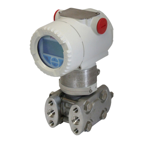
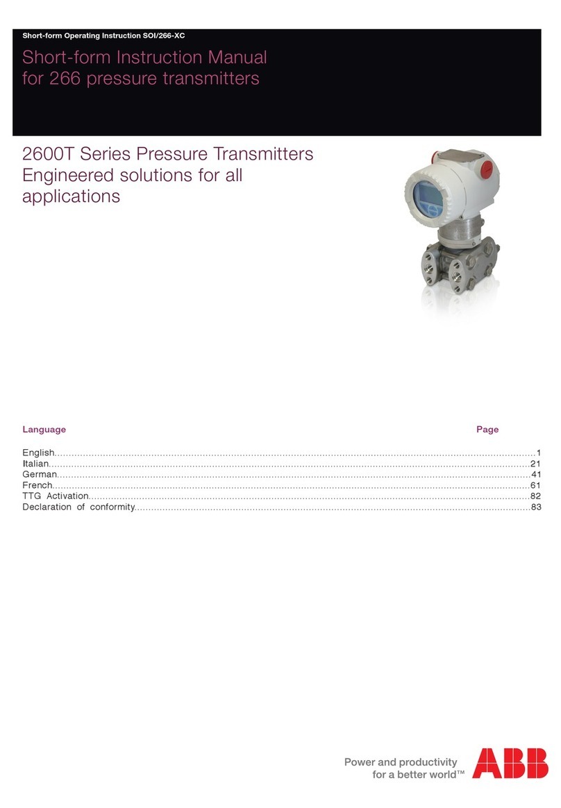
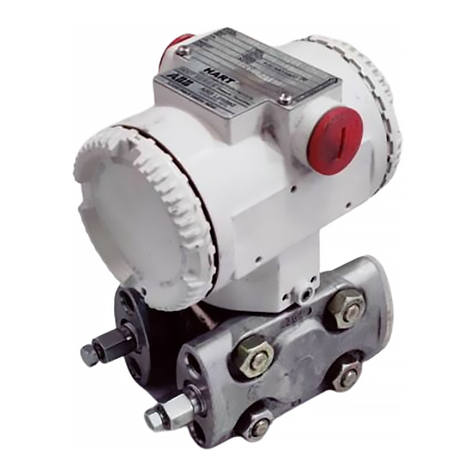
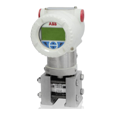
ABB 2600T Series Guide

- 1 -
Instruction for installation
and commissioning
PED/268H_2
2600T Series Safety Pressure
Transmitters
Models 268H/N

- 2 -
Health and Safety
To ensure that our products are safe and without risk to health, the following points must be noted:
1. The relevant sections of these instructions must be read carefully before proceeding.
2. Warning labels on containers and packages must be observed.
3. Installation, operation, maintenance and servicing must only be carried out by suitably trained personnel and in accordance with the
information given. Any deviation from these instructions, will transfer the complete liability to the user.
4. Normal safety precautions must be taken to avoid the possibility of an accident occurring when operating in conditions of hig h
pressure and/or temperature.
5. Chemicals must be stored away from heat, protected from temperature extremes and powders kept dry. Normal safe handling
procedures must be used.
6. When disposing of chemicals ensure that no two chemicals are mixed.
Safety advice concerning the use of the equipment described in this manual or any relevant hazard data sheets (where applicable) may
be obtained from the Company address on the back cover, together with servicing and spares information.
The Company
We are an established world force in the design and manufacture of
instrumentation for industrial process control, flow measurement, gas and
liquid analysis and environmental applications.
As a part of ABB, a world leader in process automation technology , we offer
customers application expertise, service and support worldwide.
We are committed to teamwork, high quality manufacturing, advanced
technology and unrivalled service and support.
The quality, accuracy and performance of the Company’s products result from
over 100 years experience, combined with a continuous program of innovative
design and development to incorporate the latest technology.
The NAMAS Calibration Laboratory No. 0255(B) is just one of the ten flow
calibration plants operated by the Company, and is indicative of our dedication
to quality and accuracy.
UseofInstructions
Warning.
An instruction that draws attention to the risk of injury or
death.
Caution.
An instruction that draws attention to the risk of damage
to the product, process or surroundings.
Although Warning hazards are related to personal injury , and Caution hazards are associated with equipment or property
damage, it must be understood that operation of damaged equipment could, under certain operational conditions, result in
degraded process system performance leading to personal injury or death. Therefore, comply fully with all Warning and
Caution notices.
Information in this manual is intended only to assist our customers in the efficient operation of our equipment. Use of this manual
for any other purpose is specifically prohibited and its contents are not to be reproduced in full or part without prior approval
of Technical Communications Department, ABB.
✶
Note.
Clarification of an instruction or additional information.
Information.
Further reference for more detailed information or
technical details.
ABB
EN ISO 9001: 1994
Cert. No. Q5907
ISO 9001: 2000
Cert. No. 9/90A
Cert. No. 0255
0255

- 3 -
Section Page
1. INTRODUCTION........................................................ 3
2. PHASE 1 - PRELIMINARY CHECKS
2.1 EXPLOSION PROTECTION ............................ 4
2.2 PRESSURE AND TEMPERATURE LIMITS .... 5
2.3 OPERATING VOLTAGE LIMITS ...................... 5
2.4 ENVIRONMETAL LIMITS ................................. 6
2.4.1 Electromagnetic compatibility (EMC) ........ 6
2.4.2 Humidity .................................................... 6
2.4.3 Vibration resistance .................................. 6
2.4.4 Shock resistance ...................................... 6
2.4.5 Wet and dust-laden atmospheres ............. 6
2.4.6 Fill fluid warning ........................................ 6
2.5 CORROSION ................................................... 6
2.6 SPECIAL SERVICES ....................................... 6
3. PHASE 2 - TRANSMITTER INSTALLATION
3.1 TRANSMITTER LOCATION ............................. 7
3.2 TRANSMITTER MOUNTING ............................ 9
3.3 ROTATION .................................................... 11
4. PHASE 3 - TRANSMITTER WIRING
4.1 PROTECTIVE GROUNDING ......................... 11
4.2 ELECTRICAL CONNECTIONS ...................... 11
4.3 SUPPLY WIRING REQUIREMENTS ............. 11
5. PHASE 4 - TRANSMITTER OPERATION
5.1 FLOW MEASUREMENT ................................ 12
5.2 LEVEL MEASUREMENT ................................ 13
DISMANTLING AND REASSEMBLY ..................... 14
CONTENTS 1. INTRODUCTION
This document provides basic instruction for the installation
and commissioning of the ABB 2600T. This transmitter is
connected to a process by means of impulse lines and can
measure Pressure or Absolute pressure. The measurement is
transmitted to a control system by means of a 4-20 mA signal
with a superimposed digital signal (HART) or by means of a
digital transmission protocols. The measure can also be
indicated by means of one of the (optional) local or remote
displays.
Instructions for preliminary checks, proper transmitter location,
installation, wiring, power-up and zero calibration (trimming) of
the transmitter are listed in the following.
In order to assure operator and plant safety it is essential that
the installation is carried out by personnel suitably trained on
the local applicable codes on hazardous location, electrical
wiring and mechanical piping. Please read these instructions
carefully before installing the transmitter. The protection
provided by the equipment may be impaired if the equipment
is used in a manner not specified.
For more information refer to the reference manual (document
268H/N HART Pressure Transmitters - Operating Instruction ).
These manuals are available also in electronic format on
www.abb.com searching for the keyword “IM/*26*” or from
local ABB representatives.

- 4 -
2. PRELIMINARY CHECKS
Before mounting the transmitter, check the compatibility with
the following measurement and safety requirements:
-Explosion protection
-Pressure rating
-Operating voltage limits
-Process and ambient Temperature limits
-Environmental limits
-Corrosion
2.1 EXPLOSION PROTECTION
Explosions could result in death or serious injury. Installation
of this transmitter in a Hazardous Area (i.e. a potentially
explosive atmosphere) must be in accordance with the
appropriate local, national, and international standards, codes,
and practices.
Please review the approvals and marking of the transmitter
shown on the label attached to the transmitter (see figure 1 -
Ref. C), note that this is a sample, read the values on the real
label; if this label is not present, the instrument is not suitable
for installation in Hazardous Areas. It is necessary to check
that all the parameters listed on this label (or on the certificates
enclosed with the transmitter) are in accordance with the
requirements of the area where the transmitter is going to be
installed. See the reference manual for an explanation of each
parameter related to "EX SAFETY". In case of any discrepancy
do not install the transmitter.
For pressure transmitter with ATEX combined approval, before
installation, the transmitter should be permanently marked with
the selected Protection Concept (e.g. intrinsically safe or
explosion proof) on the safety label. The transmitter can be
used only in accordance with this Protection Concept for its
whole life.
Note - The transmitter may be used as a safety
accessory (as defined by the Pressure Equipment
Directive 97/23/EC) i.e. as part of a shutdown system. In
this case it is recommended to select the correct fail safe
mode for the 4-20 mA signal (as per Namur NE43
recommendation). See also the instructions relevant to
fail safe selection (Up/Down scale mode) in the addendum
to the instruction manual on "Use of hardware links on the
secondary electronics" .
PHASE 1 - PRELIMINARY CHECKS
Fig. 1 - Product identification
Ref. B
Primary Unit
Ref. C
Ref. D
SERIAL
NUMBER
URL
DIAPHRAGM
MATERIAL
FILL
FLUID
Ref. A
not available for U.S.

- 5 -
2.2 PRESSURE AND TEMPERATURE LIMITS
The maximum allowable pressure (PS) and maximum/minimum
allowable temperature (TS) of the pressure transmitter, for
the European market are indicated on the tag plate (ref. D of
Figure 1), in the U.S. please refer to the instrument data sheets
available at: http://138.221.224.36 searching for "264 and
sheet" or from local ABB representatives.
PS and TS are defined according to the European Pressure
Equipment Directive 97/23/EC (PED). For Temperature, the
listing is for the min and max process temperature limits at
which the instrument can be exposed, for Pressure this listing
should be considered the maximum working pressure limit to
which the transmitter can be exposed without damage (to the
transmitter). These limits are valid when the transmitter is
installed according to the instructions in this manual.
WARNING ! - For potentially explosive atmosphere
applications see the temperature range specified in the
certificate/approval relevant to the intended type of
protection.
PS values
models 268HS, 268NS
- 14MPa, 140bar, 2030psi for sensor codes E, G, H, M1
- 21MPa, 210bar, 3045psi for sensor codes P, Q, S1
Proof pressure
The transmitter can be exposed without leaking to line pressure
of up to:
models 268HS, 268NS
- 28MPa, 280bar, 4060psi for sensor codes E, G, H, M1
- 40MPa, 400bar, 5800psi for sensor codes P, Q, S1
1 Sensor code is the 6th character of the product code on
label Ref. A
Meet ANSI/ISA–S 82.03 hydrostatic test requirements and
SAMA PMC 27.1.
Other 268Hx and 268Nx models using direct mount and/or
remote seal(s) are compliant to SEP (Sound Engineering
Practice).
PHASE 1 - PRELIMINARY CHECKS
WARNING ! - In order to assure the proper
containment of the process fluid by the transmitter, it is
recommended that any part, related to process fluid
containment, be supplied only by ABB or authorized agents.
The spare parts list is available at: http://138.221.224.36
searching for “SL/26*” or from local ABB representatives.
The storage conditions must be within the following limits,
Lower limit: –50°C (–58°F); –40°C (–40°F) for LCD indicators
Upper limit: +85°C (+185°F) otherwise some material such as
gaskets may be damaged and cannot assure proper fluid
containment.
2.3 OPERATING VOLTAGE LIMITS
The transmitter is designed to provide a current transmission
signal of 4 to 20 mA dc on the same wires that are carrying the
power supply (two-wire transmitter).
The transmitter operates on a minimum voltage of 10.5 Vdc to
a maximum of 42 Vdc and is protected against polarity inversion.
The transmitter operates from 10.5 to 42 Vdc with no load.
Some communication problems may occur, in cases the loop
resistance is increased by long wires or additional devices like
meters, safety barriers, surge protection, remote indicators,
etc.. If this is the case, please refer to the reference manual for
further details (the manual is available at www.abb.com inserting
in the “search” tool the keyword “IM/26X”) or from local ABB
representatives.
For EEx ia and intrinsically safe (FM, CSA and SAA) approvals,
the power supply must not exceed 30 Vdc. In some countries
the maximum power supply voltage is limited to a lower value.
The transmitter insulation resistance (terminals to earth) is
>100MΩ at 1000VDC.
CAUTION Do not arc-weld any pipe-connected to
the transmitter as this could break the electrical insulation
and damage the electronic part of the transmitter.
- 6 -
2.5 CORROSION
Be sure that the process fluid is compatible with the material of
the process flanges and sensor diaphragm.
A fluid / material compatibility table is available at www.abb.com
(inserting in the “search” tool the keyword “TB/COR”) or from
local ABB representatives.
NOTE
Data of the table are based on information from
manufacturers.
All data is based on a temperature of 20 °C, 70°F unless
noted otherwise.
Since corrosion involves many more variables than this
table considers, such as trace contaminants, aeration or
temperature-concentration profile, stress corrosion cracking
and pitting, the table should be used only as a reference in
narrowing the choice of materials that merit further
investigation. Suitability of a particular material is best
determined by field test. At this purpose, please contact our
local ABB representatives.
WARNING
For safety purpose the design corrosion allowance of
differential pressure instrument flanges is of about 1.5 mm
0.04 in. Therefore from the viewpoint of safe containment
of liquids compatible with a specific material according to
the table, the expected instrument lifetime is more than 10
years, but the previous note apply.
2.6 SPECIAL SERVICES
In case of Oxygen or Hydrogen or other special services, the
transmitter has to be handled with a special care in order to
prevent contamination with impure substances. It is
recommended to use “sterile” gloves and that the removal of
protection bags be done only immediately before the installation.
Do not flush with impure fluids.
PHASE 1 - PRELIMINARY CHECKS
2.4 ENVIRONMENTAL LIMITS
2.4.1 Electromagnetic compatibility (EMC)
Complies with EN 50081–1 for emission and EN 50082–2 for
immunity requirements and test;
Radiated electromagnetic immunity level: 30V/m (according to
IEC 1000-4-3, EN61000-4-3).
Conducted electromagnetic immunity level : 10V (according to
IEC 1000-4-6, EN 61000-4-6).
Surge immunity level (with surge protector): 4kV (according to
IEC 1000-4-5 EN 61000-4-5).
Fast transient (Burst) immunity level: 4kV (according to IEC
1000-4-4 EN 61000-4-4).
2.4.2 Humidity
Relative humidity: up to 100% annual average
Condensing, icing: admissible
2.4.3 Vibration resistance
Accelerations up to 2g at frequencies up to 1000Hz
(according to IEC 60068-2-26)
2.4.4 Shock resistance
Acceleration: 50g
Duration: 11ms (according to IEC 60068-2 27)
WARNING ! - Transmitters located in hazardous
areas must be installed in such a way to prevent the ignition
of explosive atmosphere because of impact and friction,
even in case of rare events.
2.4.5 Wet and dust-laden atmospheres
The transmitter is dust and sand tight and protected against
immersion effects as defined by IEC EN 60529 (1989) to IP 67
(that can be considered equivalent to NEMA 4X and JIS
C0920).
2.4.6 Fill fluid warning
Be sure that the fill fluid (indicated on label Ref. B) can mix safely
with the process fluid in case of rupture of the sensor membrane.

- 7 -
Min. Level
Max. Level
PHASE 2 - TRANSMITTER INSTALLATION
3. TRANSMITTER INSTALLATION
The following examples are standard mounting locations for instrumentation suitable for these main types of applications:
3.1 TRANSMITTER LOCATION
gate valve
Level measurement with open tanks
1. Mount the transmitter at the same height or below of the
lowest level to be measured.
2. Connect the transmitter to the bottom of the tank.
Pressure or absolute pressure measurement of a tank
1. Place the taps in the upper part of the tank.
2. Mount the transmitter above the elevation of the process
tap.
3. Connect the transmitter to the tank.
gate valve
Max. Level
Min. Level

- 8 -
E
S
PHASE 2 - TRANSMITTER INSTALLATION
Dirty fluids
Pressure or absolute pressure measurement of a liquid in
a pipe
1. Place the tap at the side of the line.
2. Mount the transmitter beside or below the tap for clean
fluids, above the tap for dirty fluids.
3. Connect the transmitter to the pipe.
gate valve
Clean
fluids
Pressure or absolute pressure measurement of a
condensable vapor in a pipe
1. Place the tap at the side of the line.
2. Mount the transmitter below the tap.
3. Connect the transmitter to the pipe.
4. Fill the vertical section of the connecting line to the tap with
a compatible liquid through the dedicated filling tee.
gate
valve
Pressure or absolute pressure measurement of a gas in a
pipe
1. Place the tap at the top or side of the line.
2. Mount the transmitter beside or above the tap.
3. Connect the transmitter to the pipe.
gate
valve
filling
tee
vent
valve

- 9 -
3.2 TRANSMITTER MOUNTING
Orient the process flanges to enable process connections to be
made.
It is important to mount the transmitter and to lay the process
piping so that gas bubbles, when measuring liquids, or
condensate when measuring gases, can flow back into the
process.
The vent/drain screw valves has to be ordered higher than the
taps on liquid service in order to allow the venting of entrapped
gas or below the taps on gas service in order to allow the drain
of condensate.
For safety reasons, orient the drain/vent valves so that process
fluid is directed down and away from technicians when the
valve is used. This can be accomplished by pointing the hole
in the outside valve body downward and away. In addition,
consider the need for a testing or calibration input, and provide
space for the housing covers to be removed for electrical wiring
and maintenance.
WARNING !
Process leaks may cause harm or result in death.
Install and tighten process connectors and all accessories
(including manifolds) before applying pressure.
In case of toxic or otherwise dangerous process fluid, take
any precautions as recommended in the relevant Material
Safety Data Sheet when draining or venting.
Use only a 12 mm (15/32 “) hexagonal spanner to tighten
the bracket bolts.
PHASE 2 - TRANSMITTER INSTALLATION
Traditional (Barrel) housing vertical mounting
with bracket for vertical (option B1 and B2).
Traditional (Barrel) housing direct mounting
for vertical or horizontal connections

- 10 -
PHASE 2 - TRANSMITTER INSTALLATION
3.3 ROTATION
Housing Rotation
To improve field access to wiring or the readability of the
optional LCD meter it is possible to rotate the Housing and the
Meters or the Integral display.
Housing Rotation
1. Unlock the housing rotation set screw by turning it 1 turn
(use the 3 mm Allen key supplied with the instrument)
2. Turn the housing clock wise or counterclockwise up to
180° from its original position.
Caution: over rotating will damage the transmitter.
3. Tighter the set screw.
Output Meters rotation
In case an optional meter is installed, it is also possible to rotate
the meter 90° degree clockwise or 255° counterclockwise with
15° steps.
Just turn it in the required position gripping around the complete
meter to avoid pulling the cover from the base of the meter.
set screw

- 11 -
PHASE 3 - TRANSMITTER WIRING
4. TRANSMITTER WIRING
4.1 PROTECTIVE GROUNDING
All transmitters are supplied with an external ground connection
for protective grounding.
Wire this ground connection marked with: to a suitable
earth ground.
For a transmitter measuring loop an earth ground should
maintain a resistance of 5 ohms or less.
Use a heavy conductor, at least 15 AWG / 1,6 mm2 Ø
WARNING ! - A protective grounding connection is
absolutely necessary to insure personnel protection, to
protect against surge (in case of installation of this option)
and to prevent explosions in potentially explosive
environment.
WARNING ! - In case the surge protection option is
present and the transmitter is installed in a Hazardous
area, the transmitter has to be power supplied from a
voltage source isolated from mains (galvanic separation).
Furthermore the potential equalization for the entire
powering cable must be guaranteed since the intrinsic
safety circuit of the transmitter is grounded.
4.2 ELECTRICAL CONNECTIONS
WARNING ! - Do NOT make electrical connections
unless the electrical code designation stamped on the
transmitter data plate agrees with the classification of the
area in which the transmitter is to be installed. Failure to
comply with this warning can result in fire or explosion.
The 4 to 20 mA dc output signal and the dc power supply to the
transmitter are carried from the same pairs of wires. The supply
voltage at the transmitter terminals must be between the limits
of 10,5 and 42V dc.
For Ex ia and intrinsically safe (FM, CSA and SAA) approval
power supply must not exceed 30 Vdc. In some countries the
maximum power supply voltage is limited to a lower value.
WARNING ! - Electrical shock can result in death or
serious injury. Avoid contact with the leads and terminals.
High voltage that may be present on leads can cause
electrical shock.
Follow these steps to wire the transmitter:
1. Remove the temporary plastic cap from one of the two
electrical connection ports located at both sides in the
upper part of the transmitter housing.
2. These connection ports have a 1/2 inch internal NPT
threads. Various adaptors and bushings can be fitted to
these threads to comply with plant wiring (conduit)
standards.
3. Remove the housing cover of the “field terminals” side. See
the indication on the label on top of the housing.
In an Explosion-Proof/Flame-Proof installation, do not remove
the transmitter covers when power is applied to the unit.
4. In case an Output meter is present it has to be removed by
pulling it out. Grip around the complete meter to avoid
pulling the cover from the base of the meter.
✶
5. Run the cable through the cable gland and the open port.
6. Connect the positive lead to the + terminal, and the negative
lead to the – terminal.
Note: Do not connect the power across the test
terminals. Power could damage the test diode in the test
connection.
7. Plug and seal the electrical ports. Make sure that when the
installation has been completed, the electrical ports are
properly sealed against entry of rain and corrosive vapors
and gases.
WARNING ! - Cable, cable gland and unused port
plug must be in accordance with the intended type of
protection (e.g. intrinsically safe, explosion proof, etc.) and
degree of protection (e.g. IP6x according to IEC EN 60529
or NEMA 4x). See also the addendum for "EX SAFETY"
ASPECTS AND "IP" PROTECTION. In particular, for
explosion proof installation, remove the red temporary
plastic cap and plug the unused opening with a plug
certified for explosion containment.
8. If applicable, install wiring with a drip loop. Arrange the drip
loop so the bottom is lower than the conduit connections
and the transmitter housing. In case an Output meter is
present, be sure that the by-pass connection is open, then
plug the meter into the appropriate socket.
9. Put back the housing cover, turn it to seat O-ring into the
housing and then continue to hand tighten until the cover
contacts the housing metal-to-metal.
In Ex-d (Explosion Proof) installation, lock the cover rotation
by turning the set nut (use the 2mm Allen key supplied with
the instrument).
4.3 SUPPLY WIRING REQUIREMENTS
For signal/power connection use twisted, stranded pairs of
wiring no 18 to 22 AWG / 0.8 to 0.35mm 2 ø up to 5,000 feet
(1500 meters). Longer loops require larger wire.
If a shielded wire is used the shield should be grounded only at
one end, not both ends. In case of wiring at transmitter end, use
the terminal located inside the housing marked with:

- 12 -
PHASE 4 - TRANSMITTER OPERATION
5. TRANSMITTER OPERATION
Use the following step to adjust the transmitter zero.
5.1 PRESSURE MEASUREMENT
1. Slowly open the gate valve to admit process fluid to primary of side H.
2. Vent all entrapped air (liquid service) or drain any condensate (gas service) from primary using the vent/drain valve.
3. Close the gate valve.
4. Bring the process to the desired zero reading condition, i.e.
as an example:
a. In case of dry leg open the drain valve to bring the primary to atmospheric pressure
b. In case of wet leg slowly open the filling tee (and make sure to have the wet leg completely filled-in).
5. The output should be 4mA dc. If not:
a. Rotate the nameplate to get access to the external push buttons.
b. Push the zero (Z) button on top of the transmitter (fig. 5.2) for at least 2 seconds.
c. The output goes to 4 mA, and if present the integralm display, the message "ZERO PASS" will appear.
d. If the output is not 4 Ma or the message "WRITE DISABLE" appears on the integral display, check the dip switches settings
(you need to open the cover on the electronic side and to pull out the integral display: see fig. 5.1).
e. In case of other diagnostic messages, see the reference manual.
6. Close any open filling tee and drain valve.
7. Open the gate valve.
Fig. 5.2 - Zero button
1
2
1
0
3
4
gate
valve
filling
tee
vent
valve
Fig. 5.1 - Default Dip switches setting

- 13 -
PHASE 4 - TRANSMITTER OPERATION
5.2 LEVEL MEASUREMENT
1. Vent all entrapped air from primary using vent/drain valves
on the transmitter, then close them.
2. Make sure to have the level in the tank at the required
reference (minimum) level .
Note - In case it is not possible to empty the tank, it is
possible to follow the Zero Raise/Lower adjustment
procedure described in the reference manual.
3. After venting, the output should be 4 mA dc. If not:
a. Rotate the nameplate to get access to the external push
buttons.
b. Push the zero (Z) button on top of the transmitter (fig. 5.2)
for at least 2 seconds.
c. The output goes to 4 mA, and if present the integral
display, the message "ZERO PASS" will appear.
d. If a "WRITE DISABLE" message appears on the integral
display, check the dip switches settings (you need to
open the cover on the electronic side and to pull out the
integral display: see fig. 5.1).
e. In case of other diagnostic messages, see the reference
manual.
Min. Level
Max. Level
gate valve
Max. Level
Min. Level

- 14 -
DISMANTLING AND REASSEMBLY
WARNING- Process fluids and/or pressure retained
in the transmitter primary unit can cause severe injury and
death or damage to the equipment. It is the user
responsibility to make sure that no pressure is applied
before removing the instrument from service or when
draining or venting.
Dangerous fluids.
In case of toxic or otherwise dangerous process fluid, take
any precautions as recommended in the relevant Material
Safety Data Sheet.
CAUTION- Dismantling and reassembly should not
be carried out on site because of the risk of damage to
components and printed circuits as a result of adverse
environmental conditions such as humidity,dust,etc. The
dismantling and reassembly procedures given below
should be carried out in the listed order to avoid instrument
damage.
Required tools
2 mm Allen key
3 mm Allen key
Small Phillips screwdriver
Small flat-bladed screwdriver
13 mm spanner
13 mm torque wrench - (Range > 17 Nm - 12.6 foot lbs)
Dismantling
a) Screw down completely the cover locking screw, electronics
side, using the 3 mm Allen key
b) Unscrew and remove the covers
c) Unscrew the two fixing screws and remove the
secondary electronic assembly
d) Unplug the sensor cable
e) Remove the tang grub screw using the 2 mm Allen key
f) Unscrew the housing taking care not to damage the
sensor cable or the connector.
Reassembly
WARNING - Assembling flanges with incorrect
fixing bolts and nuts and improper "O rings" can cause
fracture or overstressing of bolts and release of pressurized
process material. Use only official spare parts (*) included
in the supplementary documentation, follow the
reassembly procedure herebelow described and do not
exceed the specified torque limits. DO NOT REMOVE the
"O ring" fitted in the sensor neck: it provides the housing
a degree of protection.
a) Insert the sensor cable in its recess at the bottom of the
housing.
b) Screw the housing down completely until the nesting of
housing/sensor assy is reached, then unscrew by one
complete turn maximum. Rotate the topwork in the
desired position and lock it with the tang grub screw
previously removed.
c) Plug the sensor cable to the secondary electronics. Fix
the electronic circuit by its screws.
d) Refit the covers and tighten securely.
WARNING-ForHazardous Location installations,
atleast eight (8) threads on the cover must beengaged
in order to meet the flameproof (explosion-proof)
requirements.
e) Unscrew the cover locking screw to secure the covers.
This is mandatory to meet "Flameproof requirements"
for Hazardous Areas installation.
PRESSURE TEST WARNING
Once reassembled the process flanges and the transducer,
a pressure test is required. At this purpose, apply a hydrostatic
pressure of the maximum overrange pressure rating to both
process connections simultaneously. Wait for one minute,
then verify that no leakages occurred, otherwise repeat the
assembly procedure and the pressure test.
Transmitter Sectional View
Blind cover
Analog or digital
output indicator
Extended
windowed cover
Blind cover
Tang
screw
Terminal
blocks
assembly
Secondary electronic
Electronics screw
Sensor assembly
Nameplate
Calibration
screws

- 15 -

- 16 -

- 17 -

- 18 -

- 19 -
PRODUCTS & CUSTOMER SUPPORT
Products
Automation Systems
•for the following industries:
–Chemical & Pharmaceutical
–Food & Beverage
–Manufacturing
–Metals and Minerals
–Oil, Gas & Petrochemical
–Pulp and Paper
Drives and Motors
•AC and DC Drives, AC and DC Machines, AC Motors to 1kV
•Drive Systems
•Force Measurement
•Servo Drives
Controllers & Recorders
•Single and Multi-loop Controllers
•Circular Chart , Strip Chart and Paperless Recorders
•Paperless Recorders
•Process Indicators
Flexible Automation
•Industrial Robots and Robot Systems
Flow Measurement
•Electromagnetic Magnetic Flowmeters
•Mass Flow Meters
•Turbine Flowmeters
•Wedge Flow Elements
Marine Systems & Turbochargers
•Electrical Systems
•Marine Equipment
•Offshore Retrofit and Refurbishment
Process Analytics
•Process Gas Analysis
•Systems Integration
Transmitters
•Pressure
•Temperature
•Level
•Interface Modules
Valves, Actuators and Positioners
•Control Valves
•Actuators
•Positioners
Water, Gas & Industrial Analytics Instrumentation
•pH, conductivity, and dissolved oxygen transmitters and
sensors
•ammonia, nitrate, phosphate, silica, sodium, chloride,
fluoride, dissolved oxygen and hydrazine analyzers.
•Zirconia oxygen analyzers, katharometers, hydrogen purity
and purge-gas monitors, thermal conductivity.
Customer Support
We provide a comprehensive after sales service via a
Worldwide Service Organization. Contact one of the following
offices for details on your nearest Service and Repair Centre.
Italy
ABB S.p.A.
Business Unit Measurement Products
Tel: +39 0344 58111
Fax: +39 0344 56278
United Kingdom
ABB Limited
Tel: +44 (0)1453 826661
Fax: +44 (0)1453 827856
United States of America
ABB Inc.
Tel: +1 (0) 755 883 4366
Fax: +1 (0) 755 883 4373
Client Warranty
Prior to installation, the equipment referred to in this manual must
be stored in a clean, dry environment, in accordance with the
Company's published specification.
Periodic checks must be made on the equipment's condition. In
the event of a failure under warranty, the following
documentation must be provided as substantiation:
1. A listing evidencing process operation and alarm logs at time
of failure.
2. Copies of all storage, installation, operating and maintenance
records relating to the alleged faulty unit.

- 20 -
PED268H Rev 2
ABB Ltd
Howard Road, St. Neots
Cambridgeshire, PE19 8EU
UK
Tel: +44(0)1480 475321
Fax: +44(0)1480 217948
ABB Inc.
125 E. County Line Road
Warminster, PA 18974
USA
Tel: +1 215 674 6000
Fax: +1 215 674 7183
ABB S.p.A.
Via Statale 113.
22016 Lenno (CO)
Italy
Tel: +39 0344 58111
Fax: +39 0344 56278
ABB has Sales & Customer Support
expertise in over 100 countries worldwide
www.abb.com/instrumentation
The Company’s policy is one of continuous product
improvement and the right is reserved to modify the
information contained herein without notice.
Printed in Italy (01.2009)
© ABB 2012
Other manuals for 2600T Series
6
This manual suits for next models
1
Table of contents
Other ABB Transmitter manuals
Popular Transmitter manuals by other brands

EUTECH INSTRUMENTS
EUTECH INSTRUMENTS ALPHA PH 100 PHORP CONTROLLERTRANSMITTER instruction manual

Trikdis
Trikdis T7 user manual

RKI Instruments
RKI Instruments 65-2649RK-HC-04 Operator's manual

Extron electronics
Extron electronics DTP2 T 202 FB Setup guide

IFM
IFM efector600 TAD 61 Series operating instructions

Siemens
Siemens SITRANS P220 operating instructions