manuals.online logo
Brands
  1. Home
  2. •
  3. Brands
  4. •
  5. Abus
  6. •
  7. Control Unit
  8. •
  9. Abus FUMO50110 User manual

Abus FUMO50110 User manual

Other manuals for FUMO50110

1

Other Abus Control Unit manuals

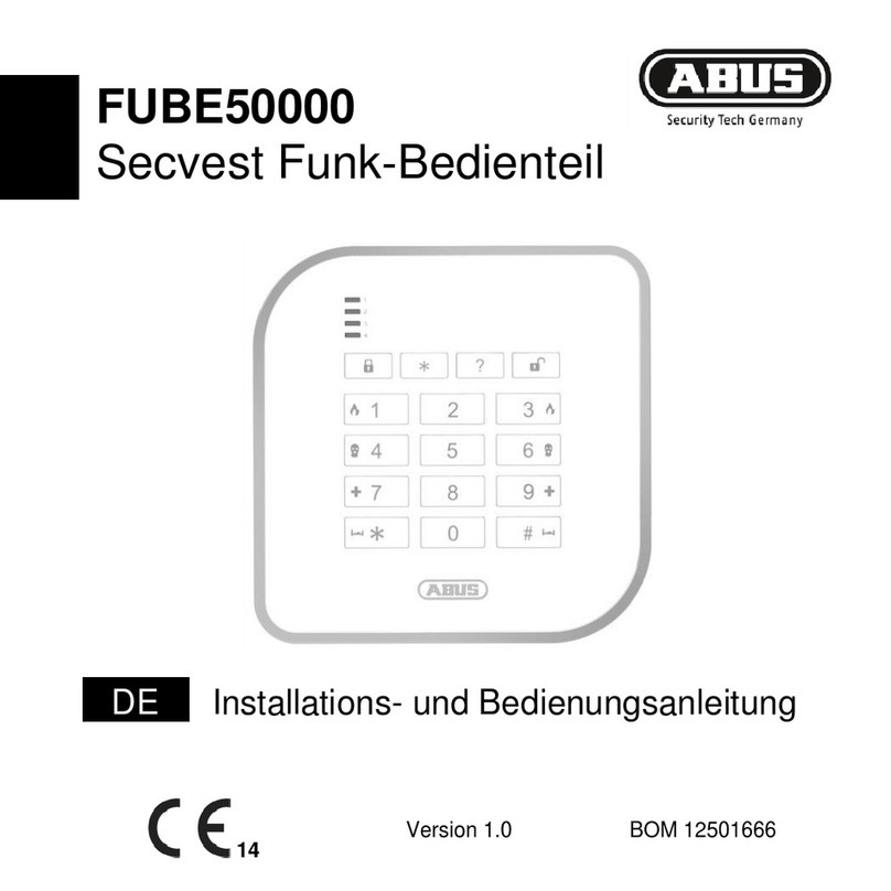
Abus FUBE50000 User manual

Abus

Abus FUBE50000 User manual

Abus Profiline AZ6451 User manual

Abus

Abus Profiline AZ6451 User manual

Abus PLHA10000 User manual

Abus

Abus PLHA10000 User manual

Abus Security Center AZ5140 User manual

Abus

Abus Security Center AZ5140 User manual

Abus FUMO50025 User manual

Abus

Abus FUMO50025 User manual

Abus FU8020 User manual

Abus

Abus FU8020 User manual

Abus ESMO50001 Mounting instructions

Abus

Abus ESMO50001 Mounting instructions

Abus FU8010 User manual

Abus

Abus FU8010 User manual

Abus PLAC90230 User manual

Abus

Abus PLAC90230 User manual

Abus ModuVis TVHS20340 User manual

Abus

Abus ModuVis TVHS20340 User manual

Abus FUMO50001 Mounting instructions

Abus

Abus FUMO50001 Mounting instructions

Abus PLHA10000 User manual

Abus

Abus PLHA10000 User manual

Abus FUMO50000 Mounting instructions

Abus

Abus FUMO50000 Mounting instructions

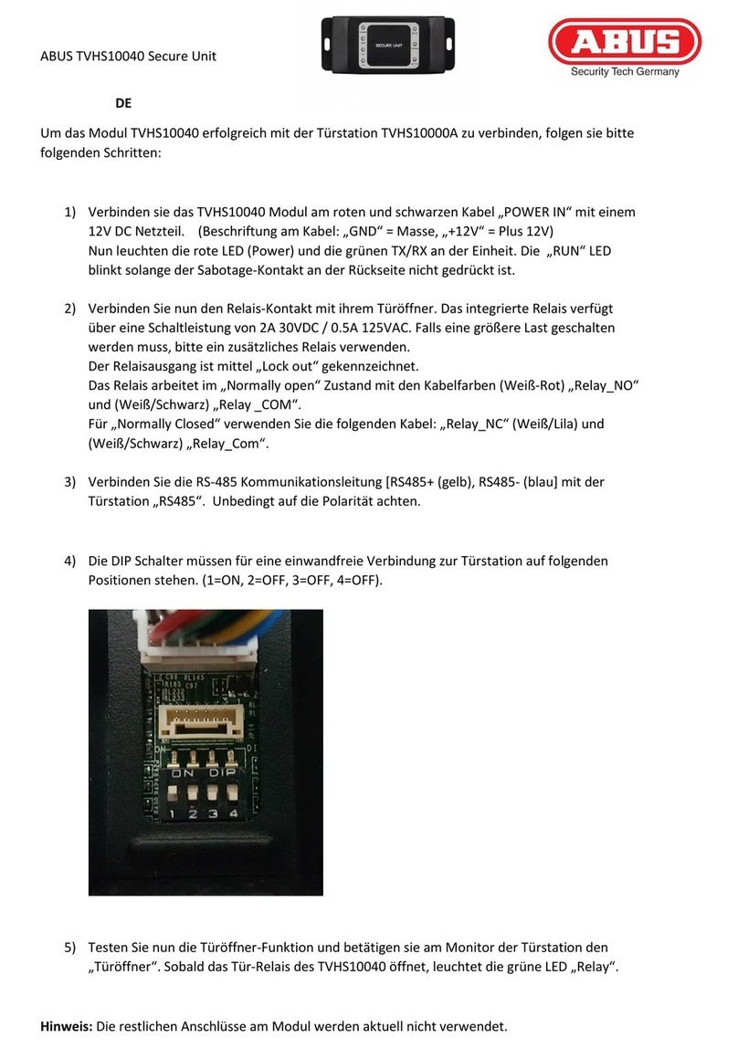
Abus TVHS10040 User manual

Abus

Abus TVHS10040 User manual

Abus FU8211 User manual

Abus

Abus FU8211 User manual

Abus FUMO50110 Mounting instructions

Abus

Abus FUMO50110 Mounting instructions

Popular Control Unit manuals by other brands

Seitz 14A80 user manual

Seitz

Seitz 14A80 user manual

Wilo RS485 Installation and operating instructions

Wilo

Wilo RS485 Installation and operating instructions

Becker CentralControl CC41 Commissioning Instruction

Becker

Becker CentralControl CC41 Commissioning Instruction

SICK CDB650 operating instructions

SICK

SICK CDB650 operating instructions

Panduit NetKey NKP5E88M Series installation instructions

Panduit

Panduit NetKey NKP5E88M Series installation instructions

MX Options Concentric Petite Fitting instructions

MX

MX Options Concentric Petite Fitting instructions

Clean Water Systems Fleck 2510 Installation & start?up guide

Clean Water Systems

Clean Water Systems Fleck 2510 Installation & start?up guide

Fairchild FSB44104A user guide

Fairchild

Fairchild FSB44104A user guide

LEGRAND Wattstopper LMIN-104 installation instructions

LEGRAND

LEGRAND Wattstopper LMIN-104 installation instructions

PMK ATT10BNCS instruction manual

PMK

PMK ATT10BNCS instruction manual

Tektronix TDS3FFT user manual

Tektronix

Tektronix TDS3FFT user manual

Woodward easYgen Technical manual

Woodward

Woodward easYgen Technical manual

Balluff BNI EIP-502-105-R015 user guide

Balluff

Balluff BNI EIP-502-105-R015 user guide

NXP Semiconductors TWR-LS1021A Getting started

NXP Semiconductors

NXP Semiconductors TWR-LS1021A Getting started

Advantech PCM-3117 Startup manual

Advantech

Advantech PCM-3117 Startup manual

Danfoss MCO 101 manual

Danfoss

Danfoss MCO 101 manual

Moons' Lin Engineering R701P user manual

Moons'

Moons' Lin Engineering R701P user manual

Aventics RV1 operating instructions

Aventics

Aventics RV1 operating instructions

manuals.online logo
manuals.online logoBrands
  • About & Mission
  • Contact us
  • Privacy Policy
  • Terms and Conditions

Copyright 2025 Manuals.Online. All Rights Reserved.

Eine alternative Inbetriebnahme sowie detaillierte Informationen erhalten Sie in
der Bedienungsanleitung erhältlich auf der Website: abus.com/product/FUMO50110
Vous trouverez une alternative de mise en service ainsi que des informations
détaillées dans le manuel d’utilisateur disponible sur le site Internet:
abus.com/product/FUMO50110
Een alternatieve ingebruikname en gedetailleerde informatie vindt u in
de gebruikershandleiding op de website: abus.com/product/FUMO50110
Per informazioni su una messa in funzione alternativa o sui dettagli del
prodotto, consultare le istruzioni per l‘uso disponibili all‘indirizzo:
abus.com/products/FUMO50110
An alternative installation as well as detailed information can be found in the
user manual which is available on the website: abus.com/product/FUMO50110
Alternativ idritagning samt detaljerede oplysninger ndes i
betjeningsvejledningen, som ndes på hjemmesiden:
abus.com/product/FUMO50110
ABUS Security-Center • Linker Kreuthweg 5
86444 Aing • Germany • abus.com
FUMO50110
QUICK GUIDE
V1.0
13112216
1x 3x
1x 1x
Quick Guide Safety Instructions
Lieferumfang • Scope of delivery • Contenu de la livraison •
Leveromvang • Indhold i kassen • Fornitura
1x
Hybrid Modul Output Kontakt Beschreibung
Zentrale OP1 NO
Input Zone Beschreibung C
Z1 NC
Z2 OP2 NO
Z3 C
Z4 NC
Z5 OP3 NO
Z6 C
Z7 NC
Z8 OP4 NO
Z9 C
Z10 NC
13112899
Anschlüsse • Connections • Raccordements • Aansluitingen •
Tilslutninger • Collegamenti
2
1
1
3
4
5 6 7 8
4
9
3
10
11
1. OP1, OP2, OP3, OP4: Schaltausgangsklemme (NO, C, NC)
2. Sabotagekontakt
3. 0-V-, 12-V-AUX-Klemme: Spannungsausgang
4. Z1, Z2, Z3, Z4, Z5, Z6, Z7, Z8, Z9, Z10: Drahtzonenklemme
5. 0V, 12V IN: Spannungsversorgungsklemme 0 V, 12 V
6. MAINS FAIL: Netzausfall-Klemme für externes Netzteil
7. LOW BATT: Klemme „Batterie schwach“
für externes Netzteil
8. -LS+: Klemme für 16-Ohm-Lautsprecher
9. Rückseitigen Sabotageschutz: Steckbrücke zum
Deaktivieren des rückseitigen Sabotageschutzes
10. TR: negativer Sabotageingang für Drahtsirene
11. TX TEST: Anzeige-LED für Senden und Test
1. OP1, OP2, OP3 OP4: Switching outputs terminal (NO, C, NC)
2. Tamper switch
3. 0V, 12V Aux terminal: voltage output
4. Z1, Z2, Z3, Z4, Z5, Z6, Z7, Z8, Z9, Z10: Wired zones terminal
5. 0V, 12V IN: Terminal for power supply 0V, 12V
6. MAINS FAIL: Mains fail terminal for external PSU
7. LOW BATT: Low battery terminal for external PSU
8. -LS+: Terminal for 16 Ohm loudspeaker
9. Disable rear tamper: Jumper for deactivating rear tamper
10. TR: negative tamper input for wired siren
11. TX TEST: Indicator LED for sending and test
1. OP1, OP2, OP3, OP4: Borne de sortie de
commutation (NO, F, NF)
2. Interrupteur anti-vandalisme
3. Borne AUX 0 V, 12 V: tension de sortie
4. Z1, Z2, Z3, Z4, Z5, Z6, Z7, Z8, Z9, Z10: Borne
de zones câblées
5. 0 V, 12 V IN: Borne pour tension d’alimentation 0 V, 12 V
6. PANNE SECTEUR: Borne panne secteur pour
bloc d’alimentation externe
7. BATTERIE FAIBLE: Borne batterie faible pour
bloc d’alimentation externe
8. -LS+: Borne pour haut-parleur 16 ohms
9. Désactivation interrupteur anti-vandalisme arrière:
Cavalier permettant de désactiver l’interrupteur
anti-vandalisme arrière
10. TR: Entrée négative anti-vandalisme pour sirène câblée
11. TEST TX: Indicateur LED d’envoi et de test
1. OP1, OP2, OP3 OP4: Geschakelde uitgangen
(normaal geopend, gesloten, normaal gesloten)
2. Sabotageschakelaar
3. 0 V-, 12 V-hulpaansluiting: uitgaande spanning
4. Z1, Z2, Z3, Z4, Z5, Z6, Z7, Z8, Z9, Z10: Aansluitblok
voor bedrade zones
5. 0V, 12V IN: Aansluitblok voor 0 V- resp. 12 V-voeding
6. MAINS FAIL: Aansluitblok voor externe voeding
als de netspanning mocht uitvallen
7. LOW BATT: Aansluitblok voor externe voeding
als de acculading laag mocht zijn
8. -LS+: Aansluiting voor een luidspreker met
een impedantie van 16 Ohm
9. Disable rear tamper: Stop voor het buiten werking
stellen van de sabotagefunctie aan de achterzijde
10. TR: negatieve sabotage-ingang voor
draadgebonden sirene
11. TX TEST: LED-indicator voor zenden en testen
1. OP1, OP2, OP3 OP4: Koblingsudgange terminal (NO, C, NC)
2. Sabotagekontakt
3. 0 V, 12 V Aux terminal: spændingsudgang
4. Z1, Z2, Z3, Z4, Z5, Z6, Z7, Z8, Z9, Z10: Trådforbundne
zoner terminal
5. 0 V, 12 V IN: Terminal til spændingsforsyning 0 V, 12 V
6. NETSPÆNDINGSFEJL: Netspændingsfejl terminal til
ekstern PSU
7. LAVT BATT: Lavt batteri terminal til ekstern PSU
8. -LS+: Terminal til højtaler på 16 ohm
9. Deaktiver sabotage bag: Jumper til deaktivering
af sabotage bag
10. TR: negativ sabotageindgang til trådforbundet sirene
11. TX TEST: Indikator LED til at sende og teste
1. Terminali di uscita (NO, C, NC) degli
switch OP1, OP2, OP3 OP4
2. Interruttore antimanomissione
3. 0V, 12V terminale Aux: tensione di uscita
4. Z1, Z2, Z3, Z4, Z5, Z6, Z7, Z8, Z9, Z10: Terminali
zone cablate
5. 0V, 12V IN: Terminale per alimentazione di
tensione 0V, 12V
6. MAINS FAIL: (alimentazione assente) Terminale
alimentazione assente per PSU esterna
7. LOW BATT: (batteria scarica) Terminale
batteria scarica per PSU esterna
8. -LS+: Terminale per altoparlante 16 Ohm
9. Disabilita manomissione posteriore Jumper per
disattivare manomissione posteriore
10. TR: Ingresso manomissione negativa per sirena cablata
11. TX TEST: Indicatore LED per invio e test
1 2
3
1
1
2
1
2
3
6
2
2
1
4
Montageanleitung • Installation instructions • Instructions
de montage • Montagehandleiding • Monteringsvejledning •
Istruzioni di montaggio
5
2
12V DC
1
1 1
1 2
Alarm contacts
Tamper contacts
FSL wiring
FSL
Verdrahtung
CC wiring
CC
Verdrahtung
2K2
4K7
Alarm contactsA larm contacts
Tamper contactsT amper contacts
Max 10 devices per circuit (not recommended)
2K2 EOL
4K7
Alarm contacts
Tamper contacts
2K2 EOL
4K7
Alarm contacts
Tamper contacts
100 Ohms
Beispiele Verdrahtung • Examples wiring • Exemples
de câblage • Voorbeelden van bedrading • Eksempler
ledninger • Esempi di cablaggio
HINWEIS ZUR INBETRIEBNAHME:
Die detaillierte Anleitung zur
Inbetriebnahme nden Sie in der
Installationsanleitung auf der abus.com
AANWIJZING VOOR DE MONTAGE:
De gedetailleerde handleiding
voor inbedrijfname vindt u in de
installateurshandleiding op abus.com.
SETUP INFORMATION:
You can nd a detailed guide
to commissioning in the
installation manual at abus.com
BEMÆRKNING VEDR. IDRIFTTAGNING:
Detaljeret vejledning vedr
idritagningen ndes i
intallationsvejledniny på abus.com
CONSIGNES DE MISE EN SERVICE:
Vous trouverez les instructions de mise
en service détaillées dans les instructions
d’installation, sur abus.com
INFORMAZIONI SULLA MESSA IN FUNZIONE:
Indicazioni dettagliate al riguardo
si trovano nelle istruzioni
d’installazione su abus.com
Z7 Z8 Z9 Z10 Z7 Z8 Z9 Z10
Z7 Z8 Z9 Z10
Zone 4
Zone 4
Zone 7
Zone 7
Zone 8
DE
Abmessungen (BxHxT): 136 x 227 x 45 mm
Gewicht
Gehäuse: 350 g
Leiterplatte: 130 g
Betriebstemperatur: -10 °C bis +55 °C
Umweltklasse II: (EN 50131-1 §7, EN 50131-3 §7)
Lufeuchtigkeit: 0–93 % RH nicht kondensierend
Schutzart: IP30
Funkfrequenz: 868,6625 MHz
Funkleistung: 10 mW
Funkreichweite: 500 m im Freien
Funk-Identikationscode: 16.777.214 (224 – 2) Varianten
Sicherheitsgrad 2
(EN 50131-1 §6, EN 50131-3 §6)
Bei Verwendung eines externen Netzteils der Ausführungsart A und B in Übereinstimmung mit EN 50131-1: 2006 + A1:
2009 + A2: 2017 §9.2 und EN 50131-6: 2008 + A1: 2014
Sabotageschutz (Erkennung/Schutz)
Ausführungsart B (EN 50131-3 §8.7)
Spannungsversorgung: 9–15 VDC
Stromaufnahme: 35mA in Ruhe / 100mA max. (Relais OP1-4 aus)
Anschlüsse für externes Netzteil
Eingang MAINS FAIL: Anschluss an potenzialfreien Netzausfall-Ausgang an externem Netzteil
Eingang LOW BATT: Anschluss an potenzialfreien Ausgang „Schwache Batterie“ an externem Netzteil
0V 12V IN: Anschluss der Spannungsversorgung
Anzahl der Spannungsausgänge: 4 - 0 V 12 V AUX bis 400 mA gesamt
Anzahl der Relaisausgänge
4 - potenzialfreie Relaisausgänge, Wechselkontakt NO / C / NC
1 A bei 24 VAC e. oder 30 VDC
Drahtzonen
10 (2-Draht-FSL/DEOL oder 2-Draht-CC)
5 (4-Draht-CC)
Negativer Sabotageeingang
TR – Der Eingang wird durch die verbundene Sirene in den inaktiven LOW-Zustand (Bezugspotenzial) geschaltet.
Die Schwellenspannung ist aktiv bei > 4V, inaktiv bei <3,6 V.
Lautsprecherklemme
Min. Impedanz: 16 Ohm
Max. Strom bei Alarm: 280 mA
Konformität
Konform mit EN 50131-1, EN 50131-3: 2009, EN 50131-5-3 und EN 50131-6
Sicherheitsgrad 2 bei ordnungsgemäßer Installation in Verbindung mit der Secvest Funkalarmanlage FUAA50xxx
EU-Richtlinien
RED: 2014/53/EU
RoHS: 2011/65/EU
WEEE: 2012/19/EU
Technische Daten • Technical data • Données techniques •
Technische specificaties • Tekniske data • Dati tecnici
EN
Dimensions (WxHxD): 136 x 227 x 45mm
Weight
Housing 350g
PCBA 130g
Operating Temperatures: -10°C to +55°C
Environmental class II: (EN50131-1 §7, EN50131-3 §7)
Humidity: 0-93 % RH non-condensing
Protection class: IP30
Radio frequency: 868.6625 MHz
Radio Power: 10mW
Wireless Range: 500m outdoors
Wireless identication code: 16.777.214 (224 – 2) variants
Security level 2
(EN50131-1 §6, EN50131-3 §6)
When using external power supply of types A and B compliant with EN50131-1: 2006 + A1: 2009 + A2: 2017 §9.2
and EN50131-6: 2008 + A1: 2014
Tamper protection (detection/protection)
Type B (EN50131-3 §8.7)
Power supply: 9-15V DC
Power consumption: 35mA quiescent / 100mA max. (relay OP1-4 o)
Connections for external power supply
MAINS FAIL input. Connect to mains fail voltage free output on external PSU.
LOW BATT input. Connect to low batt voltage free output on external PSU.
0V 12V IN - Power supply connection
Number of voltage outputs: 4 - 0V 12V AUX up to 400mA total
Number of Relay outputs
4 - relay output potential-free, changeover contact NO / C / NC
1A @ 24 V AC rms or 30 V DC
Wired Zonen
10 (2-wire FSL/DEOL or 2-wire CC)
5 (4-wire CC)
Negative sabotage entrance
TR - The input is switched to the inactive low state (ground potential) through the connected siren.
The threshold voltage is active for> 4 V, for inactive <3.6 V.
Loudspeaker terminal
Min impedance 16 ohms
Max current in alarm 280mA
Conformity
is compliant with EN 50131-1, EN50131-3: 2009, EN50131-5-3 and EN50131-6
Security level 2 when properly installed in conjunction with the Secvest wireless alarm system FUAA50xxx.
EU Directives
RED: 2014/53/EU
RoHS: 2011/65/EU
WEEE: 2012/19/EU
FR
Dimensions (L x H x P): 136 x 227 x 45 mm
Poids
Boîtier 350 g
Circuit imprimé 130 g
Températures de fonctionnement: -10 °C à +55 °C
Classe d’environnement II: (EN50131-1 §7, EN50131-3 §7)
Humidité: 0 à 93 % d’humidité relative (sans condensation)
Classe de protection: IP30
Fréquence radio: 868,6625 MHz
Puissance radio: 10 mW
Portée radio: 500 m en extérieur
Code d’identication radio: 16.777.214 (224 – 2) variantes
Degré de sécurité 2
(EN50131-1 §6, EN50131-3 §6)
En cas d’utilisation d’une tension d’alimentation externe de type A et B conforme à EN50131-1: 2006 + A1: 2009 + A2: 2017
§9.2 et EN50131-6: 2008 + A1: 2014
Protection anti-vandalisme (détection/protection)
Type B (EN50131-3 §8.7)
Tension d’alimentation: 9 à 15 V CC
Consommation d’énergie: 35mA au repos / 100mA max. (relais OP1-4 désactivé)
Connexions pour tension d’alimentation externe
Entrée PANNE SECTEUR. Connexion à la sortie panne secteur sans tension sur bloc d’alimentation externe.
Entrée BATTERIE FAIBLE. Connexion à la sortie batterie faible sans tension sur bloc d’alimentation externe.
0 V, 12 V IN – Connexion pour tension d’alimentation
Nombre de sorties tension: 4 - 0 V 12 V AUX jusqu’à 400 mA au total
Nombre de sorties relais
4 - sortie relais sans potentiel, contact inverseur NO/F/NF
1 A à 24 V CA rms ou 30 V CC
Zones câblées
10 (FSL/DEOL à 2 ls ou CC à 2 ls)
5 (CC à 4 ls)
Entrée négative sabotage
TR – L’entrée est commutée sur l’état inactif (potentiel de terre) via la sirène connectée.
La tension seuil est active pour > 4 V, inactive pour > 3,6 V.
Borne de haut-parleur
Impédance min. 16 ohms
Courant max. en alarme 280 mA
Conformité
Conforme aux normes EN 50131-1, EN50131-3: 2009, EN50131-5-3 et EN50131-6
Degré de sécurité 2 si installation correcte associée au système d’alarme sans l Secvest FUAA50xxx.
Directives UE
RED : 2014/53/UE
RoHS : 2011/65/UE
WEEE : 2012/19/UE
NL
Afmetingen (b x h x d): 136 x 227 x 45mm
Massa
Behuizing: 350 g
Samengestelde printkaart: 130 g
Bedrijfstemperaturen: -10 ... +55 °C
Milieuklasse II: (EN50131-1 §7, EN50131-3 §7)
Vochtigheid: 0 ... 93% relatieve luchtvochtigheid, niet-condenserend
Beschermklasse: IP30
Radiofrequentie: 868,6625 MHz
Zendvermogen: 10 mW
Draadloos bereik: 500 m buitenshuis
Draadloze identicatiecode: 16.777.214 (224 – 2) varianten
Veiligheidsniveau 2
(EN50131-1 §6, EN50131-3 §6)
Bij gebruik van een externe voeding van type A of B in overeenstemming met de norm EN50131-1: 2006 + A1: 2009 + A2:
2017 §9.2 en met de norm EN50131-6: 2008 + A1: 2014
Sabotagebescherming (detectie resp. bescherming)
Type B (EN50131-3 §8.7)
Voeding: 9 ... 15 V=
Opgenomen vermogen: 35mA in rust / 100mA max. (relais‘ OP1 ... 4 afgevallen)
Aansluitingen voor externe voeding
"MAINS FAIL"-ingang. Aansluiting voor externe voeding als de netspanning mocht uitvallen.
"LOW BATT"-ingang. Aansluiting voor externe voeding als de acculading laag mocht zijn.
0V, 12V IN - Aansluiting voor voeding
Aantal spanningvoerende uitgangen: 4 - 0 V, 12 V AUX tot maximaal 400 mA (totaal)
Aantal relaisuitgangen
4 - potentiaalvrije relaisuitgangen, wisselcontacten normaal geopend / gesloten / normaal gesloten
1 A @ 24 Ve of 30 V=
Bedrade zones
10 (tweedraads FSL/DEOL of tweedraads CC)
5 (vierdraads CC)
Negatieve sabotage-ingang
TR - De ingang wordt naar een inactieve, logisch lage status geschakeld (aardpotentiaal) en wel via een daarop
aangesloten sirene. De drempelspanning bedraagt in actieve modus > 4 V, en <3,6 V in inactieve modus..
Aansluitblok voor luidspreker
Minimale impedantie: 16 Ohm
Maximaal opgenomen stroom in alarmmodus: 280 mA
Overeenstemming
In overeenstemming met de normen EN 50131-1, EN50131-3: 2009, EN50131-5-3 en EN50131-6
Veiligheidsgraad 2 mits correct geïnstalleerd in combinatie met het draadloze alarmeersysteem Secvest FUAA50xxx
Europese Richtlijnen
RED: 2014/53/EU
RoHS: 2011/65/EU
WEEE: 2012/19/EU