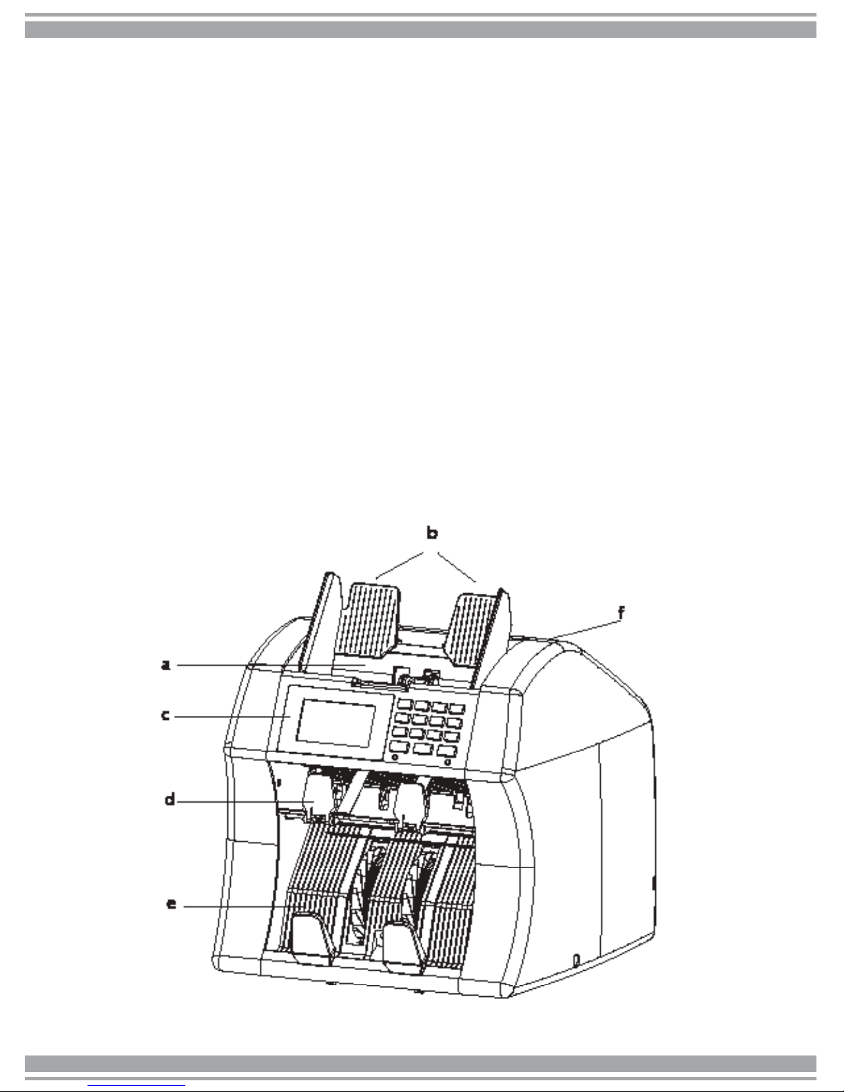
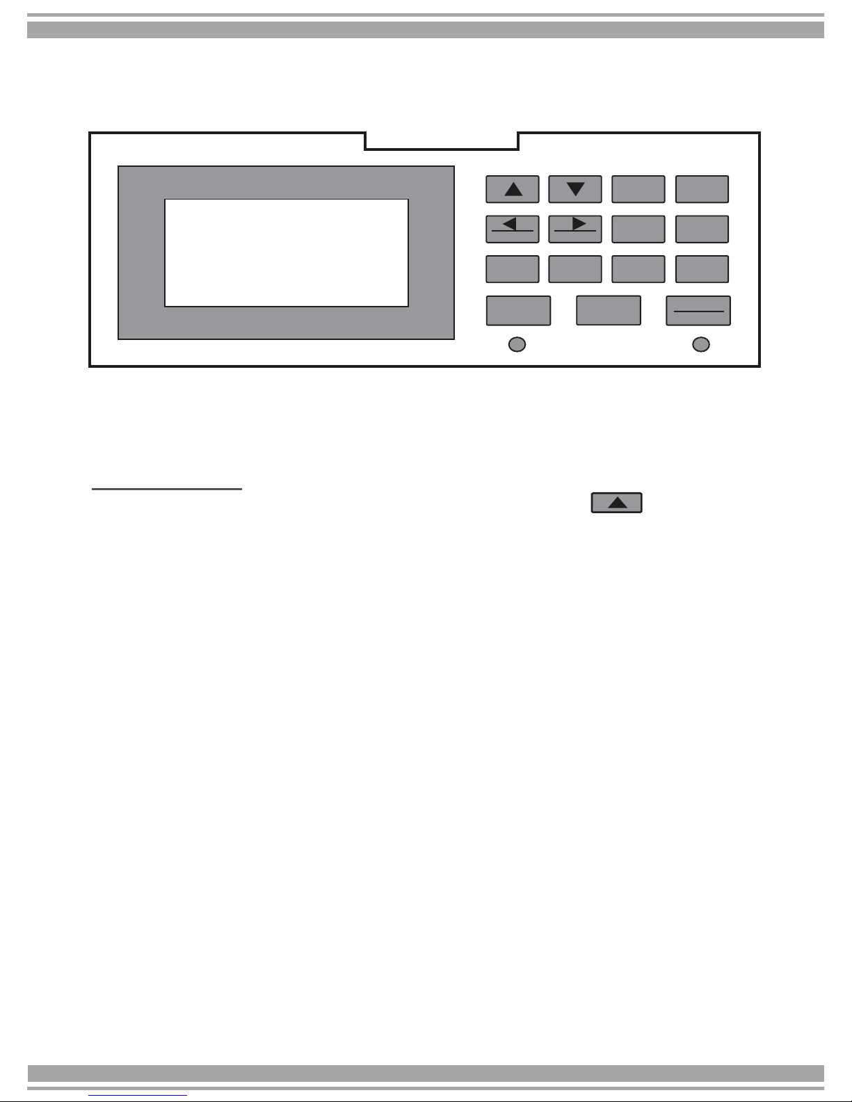
AccuBANKER AB7500 User manual
Other AccuBANKER Cash Counter manuals

AccuBANKER
AccuBANKER D585 User manual

AccuBANKER
AccuBANKER LED420 User manual

AccuBANKER
AccuBANKER AB5200 User manual

AccuBANKER
AccuBANKER AB630 User manual

AccuBANKER
AccuBANKER AB1050 User manual

AccuBANKER
AccuBANKER AB610 User manual

AccuBANKER
AccuBANKER SILVER S6500 User manual

AccuBANKER
AccuBANKER AB5800 User manual

AccuBANKER
AccuBANKER AB550 User manual

AccuBANKER
AccuBANKER AB-1100 Plus UV User manual