1-5
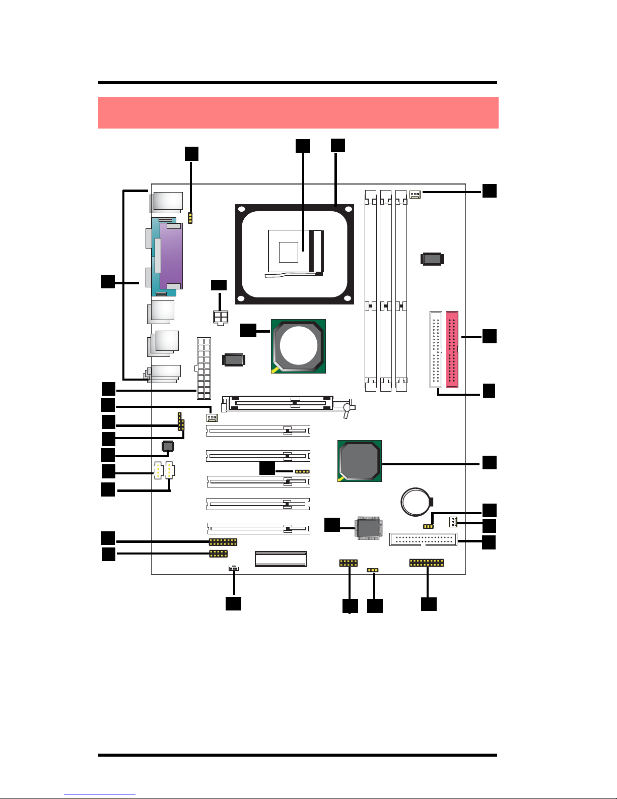
Chapter 1 Motherboard 4S648/4S648N
The 4S648/4S648N motherboard is an integration of Intel
P4 CPUs in Socket-478 packaging and the North Bridge
SiS648 supporting 533/400 MHz Front Side Bus.
North Bridge SiS648 on board also supports DDR 333/
266/200 DRAMs and the integrated AGP 8X/4X Interface,
while the South Bridge SiS963L provides stable supports of
ULTRA ATA 133/100, 6-channel Audio playback, integrated
Digital Audio Controller, LPC Super I/O, USB 2.0/1.1 interfac.
PCI interface as well as integrated 10/100Mbit Fast Ethernet
LAN Controller.
The resulting architecture will provide an ideal multi-task
environment to support operating systems such as MS-DOS,
Windows, Windows NT , Windows ME, Windows 2000, Novell,
OS/2, Windows 95/98, Windows 98SE, Windows XP, UNIX,
Liunx, SCO UNIX etc. This user-friendly manual is to de-
scribe in detail how to install, configure and use this
motherboard with drivers and BIOS setup illustrations.
Chapter 1
4S648/4S648N
1.1 Introduction
1. 4S648/4S648N Specifications
This manual is a general reference of the first release of this
motherboard which is subject to update without notice. If any differ-
ence is found between this manual and the motherboard you are
using, please refer to the Web Site.