INTRODUCTION
Table of Contents
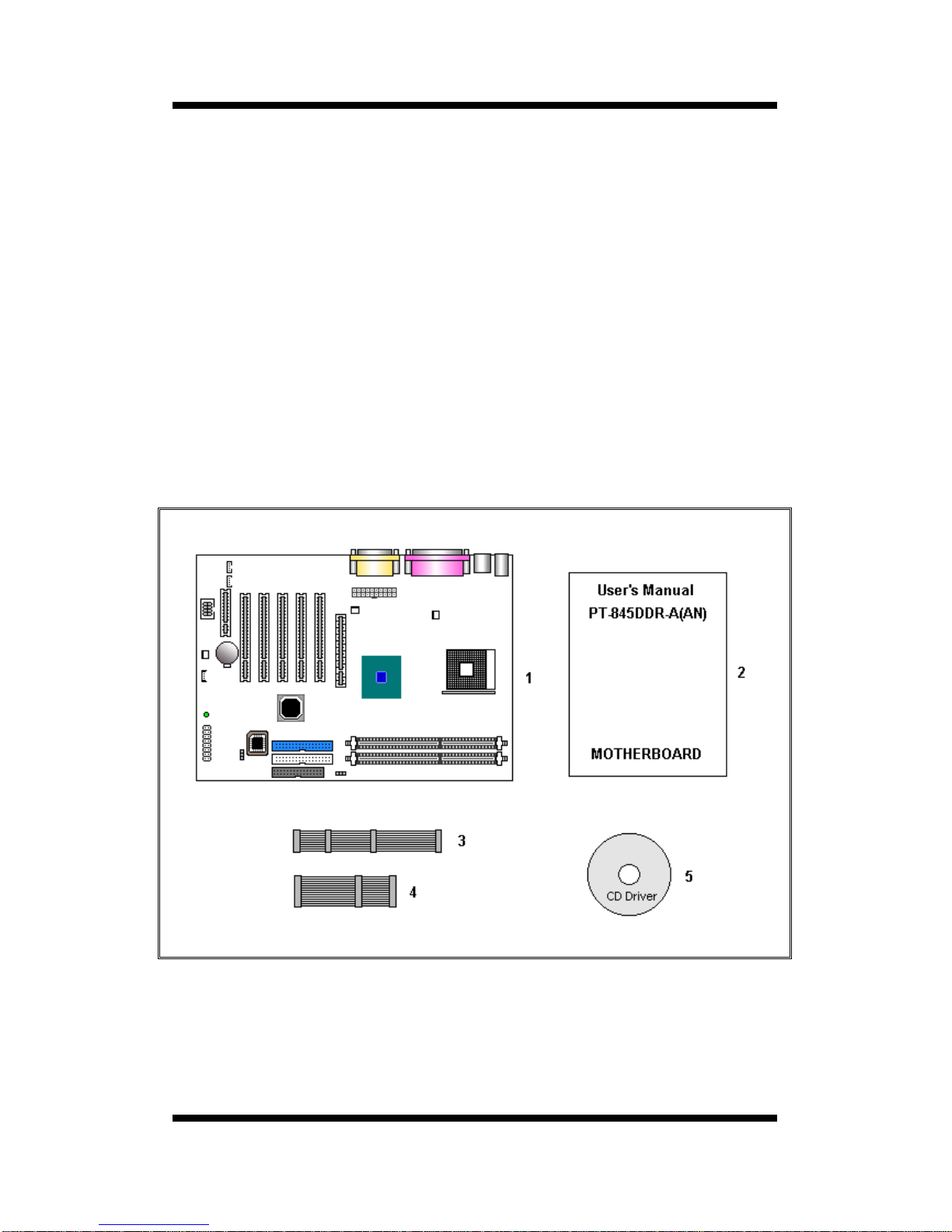
PACKAGE CHECKLIST
CHAPTER 1
1. INTRODUCTION OF 4D533 MOTHERBOARD................
1.1 Product Description..................................................................................
1.2 System Block Digram...............................................................................
1.3 Features & Specifications .............................................................................
1.4 Board Level Feature.....................................................................................
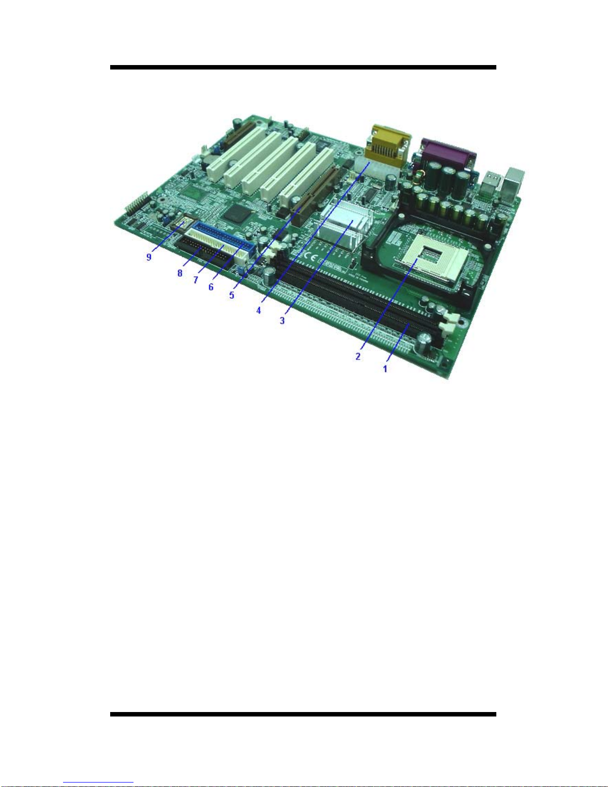
1.5 Comprehensive Mainboard View ............................................................
2. HARDWARE INSTALLATION ..........................................................................
2.1 Jumper Setting .............................................................................................
2.1 .1 Setting the Jumpers ............................................................................
2.1 .2 Clear CMOS................................................................................................
2.1.3 Flash BIOS Write Protect/Enable (JP4) .......................................................
2.1.4 SMART Card....................................................................................
2.2 Connect ions............................................................................................
2.2.1 Installing the CPU ...................................................................................
2.2.2 Installing the Heatsink and Fan. ..........................................................
2.2.3 Cooling Fan............................................................................................
2.2.4 Installing the Memory Modules (DIMM)........................................................
2.2.5 Floppy Drives......................................................................................
2.2.6 IDE Hard Drivers and CD-ROMs Drives ................................................
2.2.7 Power LED Connections ........................................................................
2.2.8 Power Supply Connector ......................................................................
2.2.9 IrDA-Compliant Infrared Module Connector...........................................
2.2.10 LAN Wake-up Connector..........................................................................
2.2.11 External Connectors.............................................................................
2.2.12 Installing an AGP Card ........................................................................
2.2.13 Installing an PCI Card.....................................................................
2.2.14 Installing an CNR Card ........................................................................
2.2.15 Onboard LED..............................................................................................
3. MAINBOARD BIOS SETUP................................................................................
3.1 About the BIOS .......................................................................................
3.2 Main Menu ...............................................................................................
3.3 Standard CMOS Features .....................................................................
7
7
8
9
10
12
13
13
13
14
14
15
13
16
17
18
19
20
20
21
22
22
23
23
27
27
28
28
29
29
31
32
User's Manual
4