6 / Chapter 1 Motherboard Description6 / Chapter 1 Motherboard Description
6 / Chapter 1 Motherboard Description6 / Chapter 1 Motherboard Description
6 / Chapter 1 Motherboard Description
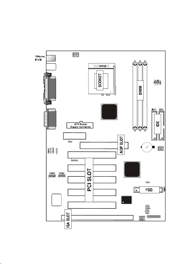
1.3 Motherboard Connectors
12
7
8
10
9
6
13
USB1
IR
FAN2
JP2
FAN1
JACK1
JACK2
JACK3
GAME1
VIA
VIA
J1
1
FAN3
LAN CHIP
AMR SLOT
AGP SLOT
JP1
ISA SLOT
PCI1
PCI2
PCI3
PCI4
PCI5
DIMM3
DIMM2
DIMM1
462
BIOS
COM1
VGA1
Printer
15
4,5
1.Back Pannel I/O Connectors1.Back Pannel I/O Connectors
1.Back Pannel I/O Connectors1.Back Pannel I/O Connectors
1.Back Pannel I/O Connectors 2.CD Audio-In Connector2.CD Audio-In Connector
2.CD Audio-In Connector2.CD Audio-In Connector
2.CD Audio-In Connector
3.AMR CODEC Fuction(JP1)3.AMR CODEC Fuction(JP1)
3.AMR CODEC Fuction(JP1)3.AMR CODEC Fuction(JP1)
3.AMR CODEC Fuction(JP1) 4.Wake-On MODEM Connector4.Wake-On MODEM Connector
4.Wake-On MODEM Connector4.Wake-On MODEM Connector
4.Wake-On MODEM Connector
5.Wake-On-LAN Connector5.Wake-On-LAN Connector
5.Wake-On-LAN Connector5.Wake-On-LAN Connector
5.Wake-On-LAN Connector 6.Front Two USB Connector6.Front Two USB Connector
6.Front Two USB Connector6.Front Two USB Connector
6.Front Two USB Connector
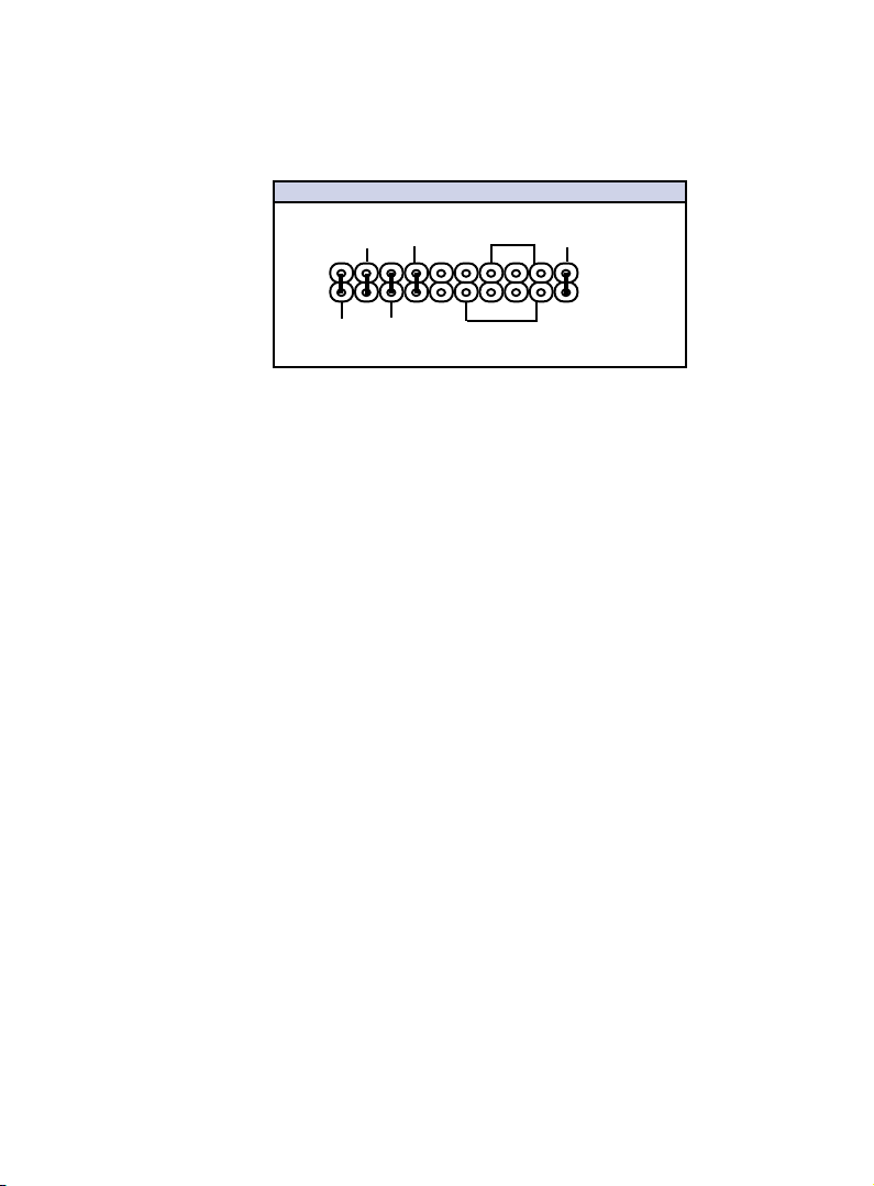
7.Front Panel Connector7.Front Panel Connector
7.Front Panel Connector7.Front Panel Connector
7.Front Panel Connector 8.Fan connectors(Fan1/2/3)8.Fan connectors(Fan1/2/3)
8.Fan connectors(Fan1/2/3)8.Fan connectors(Fan1/2/3)
8.Fan connectors(Fan1/2/3)
9.IDE Connectors9.IDE Connectors
9.IDE Connectors9.IDE Connectors
9.IDE Connectors 10.Floppy Connector10.Floppy Connector
10.Floppy Connector10.Floppy Connector
10.Floppy Connector
11.CPU Clock Selection(SW1)11.CPU Clock Selection(SW1)
11.CPU Clock Selection(SW1)11.CPU Clock Selection(SW1)
11.CPU Clock Selection(SW1) 12.IR Connector12.IR Connector
12.IR Connector12.IR Connector
12.IR Connector
13.ATX Power Connector13.ATX Power Connector
13.ATX Power Connector13.ATX Power Connector
13.ATX Power Connector
14.CMOS Function Selection(JP2)14.CMOS Function Selection(JP2)
14.CMOS Function Selection(JP2)14.CMOS Function Selection(JP2)
14.CMOS Function Selection(JP2)
15.Front Two COM Connector15.Front Two COM Connector
15.Front Two COM Connector15.Front Two COM Connector
15.Front Two COM Connector
1
11
14
2
3