Acorp 4845GLM User manual

0-1
Contents Motherboard 4845GLM
Motherboard
4845GLM
1. 4845GLM Specifications...................4
1.1Introduction ............................................................ 4
1.2 Package Contents .................................................. 4
1.3 Specifications and Features .................................. 5
CPU Processor ...........................................................................5
Chipset ........................................................................................5
PCI ..............................................................................................5
DDR SDRAMMemory...............................................................5
VGAOnBoard ............................................................................5
Bus Slots.....................................................................................5
Universal Serial Bus ..................................................................5
WOL(WakeOnLAN) ................................................................5
AwardBIOS ................................................................................6
ATA100 OnBoard .....................................................................6
PCI-Based AC 97 Digital Audio Processor ...............................6
1.4 4845GLM Layout Diagram ................................. 7
1.5 CPU and CPU Fan Installation.............................. 9
1.5.1 CPU Installation with Socket 478 .....................................9
1.5.2CPU Fan Installation with P4 Fan Base...........................10
1.6 DDR SDRAM Installation ................................. 11

0-2
Contents Motherboard 4845GLM
1.7 Connectors & Jumpers Setting ........................... 12
1.7.1 Back Panel I/O Connectors.............................................12
1.7.1.1 PS/2 Mouse / Keyboard CONN. .............................................. 12
1.7.1.2 USB Port Connector: USB1..................................................... 12
1.7.1.3 Serial Interface Port: COM1 .................................................. 13
1.7.1.4 VGA Interface Connector: VGA(15 Pin)............................. 13
1.7.1.5 Parallel Interface Port .............................................................. 13
1.7.1.6 Joystick / Midi Connector........................................................ 13
1.7.1.7 Audio Port Connectors ............................................................. 13
1.7.2ATX MainPower Connectors:PW1/PW2 ......................14
1.7.3Floppy DiskConnector:FDD..........................................15
1.7.4Hard DiskConnectors:IDE1/IDE2 ................................15
1.7.5Fan Connectors: FAN1~3 ................................................15
1.7.6CDAudio-InConnectors:CD_IN/AUX ...........................16
1.7.7 USB Pin Headers: USB2 & USB3...................................17
1.7.8FrontPanelConnectors:PANEL1 ..................................18
1.7.9 IRinfraredmodule:IRConnector ...................................19
1.7.10 CMOS Function Selector: JP8 .....................................20
1.7.11 CNR Selector: JP6 ........................................................20
1.7.12 CPU Clock Frequency Selector: JP1 ............................21
2. BIOS Setup ..................................... 22
2.1 BIOS Support....................................................... 22
2.2 Main Menu .......................................................... 25
2.3 Standard CMOS Features .................................. 28
2.4 Advanced BIOS Features ................................... 31

0-3
Contents Motherboard 4845GLM
2.5 Advanced Chipset Features ................................ 35
2.6 Integrated Peripherals......................................... 38
2.7 Power Management Setup .................................. 46
2.8PnP/PCIConfigurations....................................... 50
2.9 PC Health Status ................................................. 53
2.10 Miscellaneous Control ...................................... 55
2.11 Load Optimized Defaults ................................... 56
2.12 Load Standard Defaults .................................... 57
2.13 Set Supervisor / User Password ........................ 58
2.14 Save & Exit Setup ............................................. 60
2.15 Exit Without Saving ........................................... 61
3. Drivers & Utilities ........................... 62
3.1Auto-runMenu .................................................... 62
3.2 Installing Intelinf.................................................. 63
3.3InstallingApplicationAccelerator ...................... 66
3.4 Installing Audio Driver ........................................ 69
3.5 Installing VGA Driver ......................................... 71
3.6 Installing USB 2.0 Device ................................... 75
3.6.1 Install USB2.0 driver for Win 2000................................75
3.6.2 Install USB2.0 driver for Win XP ...................................75

1-4
Chapter 1 Motherboard 4845GLM
The 4845GLM motherboard is an integration of Intel
P4 CPUs in Socket-478 packaging and the North Bridge
i845GL supporting 400 MHz Front Side Bus.
North Bridge i845GL on board also supports DDR 266/
200DRAMsinDDR266MHzmainbandwidth,whiletheSouth
Bridge ICH4 provides stable supports of ULTRA ATA 100,
6-channel Audio playback and USB 2.0/1.1 interface.
The resulting architecture will provide an ideal multi-
task environment to support operating systems such as MS-
DOS, Windows, Windows NT , Windows ME, Windows
2000, Novell, OS/2, Windows 95/98, Windows 98SE, Win-
dows XP, UNIX, Liunx, SCO UNIX etc. This user-friendly
manual is to describe in detail how to install, configure and
usethis motherboard with drivers andBIOS setup illustrations.
Chapter 1
Motherboard 4845GLM
HDD UDMA66/100 Cable.
FDD Cable.
Flash Memory with BIOS.
USB2/3 Cable (Optional).
Fully Setup Driver CD with built in utilities.
User Manual.
1.1Introduction
1.2 Package Contents
1. 4845GLM Specifications

1-5
Chapter 1 Motherboard 4845GLM
CPU Processor
| Support 400MHz System Interface speed.
| Single Socket 478 for Intel P4TM 1.5 to 2.4GHz or higher
(Northwood Processor).
| Support Intel NetburstTM Micro-architecture.
Chipset
| Intel 845GL North Bridge.
| Intel ICH4 South Bridge.
PCI
| Supports 33MHz PCI Bus speed.
DDR SDRAM Memory
| Supporting 64/128/256/512....MB DDR module
| Supporting Synchronous DRAM(2.5V)
| Supporting a maximum memory size of 2GB with DDR
SDRAM.
VGAOn Board
| 2D, 3D Graphics display supported on board
| 15-pin Connector on board for VGA CRT display
Bus Slots
| 3 32-bit PCI slots.
Universal Serial Bus
| Supporting two on-board Universal Serial Bus(USB)Ports
and four external Universal serial Bus(USB)Ports.
| Supporting USB 2.0/1.1
WOL (Wake On LAN)
| Supporting system power-on by LAN Ring-up signal.
1.3 Specifications and Features

1-6
Chapter 1 Motherboard 4845GLM
Award BIOS
| Supporting Plug & Play specification which detects the
peripheral devices and expansion cards automatically
| Supporting CD-ROM, SCSI, LAN BOOT, Temperature sen-
sor, LAN, Alarm Bus CLK setup
| Supporting Desktop Management Interface (DMI) func-
tion for recording mainboard specification
ATA 100 On Board
| Supporting four IDE devices.
| Supporting PIO Mode 5, Master Mode, high performance
hard disk drives.
| Supporting Ultra DMA 33/66/100 Bus Master Mode.
| Supporting IDE interface with CD-ROM.
| Supporting high capacity hard disk drives.
| Supporting LBA mode.
PCI-Based AC 97 Digital Audio Processor
| AC 97 2.1Audio interface.
| 16-bit Stereo Full-Duplex Codec with up to 48 KHz samp-
ling rate
| 4 Analog Line-level Stereo inputs for connection from Line,
CD, Viedo and AUX
| 2 Analog Line-level Stereo inputs for speakerphone and PC
beep

1-7
Chapter 1 Motherboard 4845GLM
Intel
ICH4
LPC I/O
Chip
mPGA478B
Socket 478
Intel
845GL
Battery
BIOS
W83194BR
16 17
1
1411
6
15
12
20
13
4
9
8
3
1.4 4845GLM Layout Diagram
10
19
18
7
PCI 1
PCI 2
PCI 3
DIMM 1
DIMM 2
2
21
25 2324 22
5
26

1-8
Chapter 1 Motherboard 4845GLM
7. USB2: Pin Header for 2 USB ports
8. AC’97 Audio Codec
9. IR: Connector for Infrared transfer mode
10. LPC I/O Chip
11. CNR Slot: Slot for CNR Riser cards
12. JP6: Jumper as CNR Slot Selector
13. Floppy: Floppy Drive Connector
14. WOL: Wake-On-LAN Connector
15. USB3: Pin Header for two USB ports
16. JP8: Jumper for clear CMOS RAM
17. Front Panel Connectors: PWRLED, SPK, RST, SMI, HDLED,
PSON
18. FAN 3: Cooling Fan Connector
19. IDE1: Primary IDE Connector
20. IDE2: Secondary IDE Connector
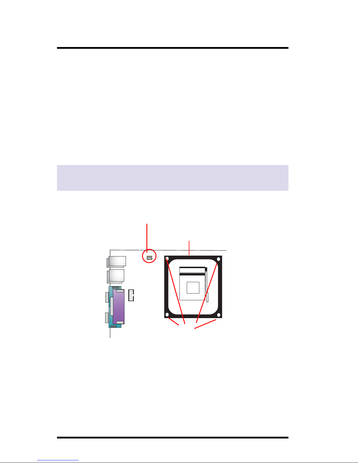
21. CPU Fan Base
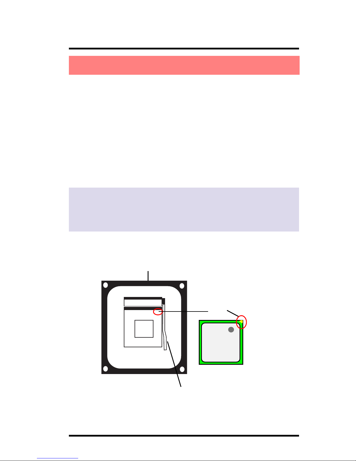
22. mPGA478B: Socket 478 for P4 CPUs
23. FAN 3: Cooling Fan Connector
24. PW1: +12V Power Connector
25. COM2: Connector for Serial port
26. Back Panel: Back Panel I/O Connectors (Mouse, Keyboard,
USB1, COM1, VGA, Printer, MIC in, Line in, Speaker-
out, Game stick)
1. PW2: Main Power Connector
2. Fan 2: Cooling Fan Connector
3. JP1: Jumper as CPU Clock Selector
4. AUX: Audio-in Connector
5. CD_IN: CD Audio-in Connector
6. Front Audio: Front Audio Connector
4845GLM Component Layout Description:

1-9
Chapter 1 Motherboard 4845GLM
mPGA478B
Socket 478
This motherboard is designed with Socket 478 for
Intel P4TM processor.
Pin 1
1.5CPUandCPUFanInstallation
1. Pull the lever sideways away from the socket then raise the
lever to a 90-degree angle.
2. Locate Pin 1 in the socket Pin 1 of CPU is marked by the
yellow corner or cut edge on the CPU. Match Pin 1 of
Socket 478 and Pin 1 of CPU.
3. Pull up the lever of Socket 478 to let the CPU in and press
the lever down to lock the CPU.
4. Make sure that Pin 1 of Socket 478 is matching with Pin 1 of
CPU.
5. Make sure that all CPU pins are completely in socket before
pressing down the socket lever.
Intel
pentium 4
Level of Socket 478
Cooling Fan Base
1.5.1 CPU Installation with Socket 478

1-10
Chapter 1 Motherboard 4845GLM
1.5.2 CPU Fan Installation with P4 Fan Base
1. P4 CPU Fan is typically made of 4 latches and mounted with
a thick heatsink. Please do not use other type of CPU fan
which cannot match the P4 Fan base on board.
2. Install the P4 CPU fan into the Fan base in such a way that
the 4 latches of the CPU Fan match with the 4 Supporters of
the CPU Fan Base.
3. Press down the latches to lock CPU Fan to the Fan Base.
4. Then connect the Fan Power Cable to one of the Fan con-
nectors on board.
5. Make sure that the Fan Power Cable is correctly connected
to Fan Connector.
mPGA478B
Socket 478
Fan Base
4 Latch Supporters
Fan Connector for Fan Power Cable
Mainboard

1-11
Chapter 1 Motherboard 4845GLM
This motherboard supports a maximized 2GB DDR 266/
200 SDRAM. It provides two184-pin unbuffered DDR
sockets. It supports 64MB to 1GB DDR memory module.
DDRSDRAMInstallationProcedures:
1. The DDR socket has a “Plastic Safety Tab” and the DDR
memory module has an asymmetrical notch”, so the DDR
memory module can only fit into the slot in one direction.
2. Push the tabs out. Insert the DDR memory modules into the
socket at a 90-degree angle then push down the module
vertically to fit it into place.
3. The Mounting Holes and plastic tabs should fit over the
edge and hold the DDR memory modules in place.
Warning: Be sure to turn off system power whenever to insert or
remove a Memory Module. Otherwise, the power will damage the
module or even the system.
1.6DDRSDRAMInstallation
Bank Memory module
DIMM 1 64MB, 128MB, 256MB, 512MB, 1GB
184 pin, 2.5V DDR SDRAM
DIMM 2 64MB, 128MB, 256MB, 512MB, 1GB
184 pin , 2.5V DDR SDRAM
Total System Memory (Max 2GB)
184-pin DDR Module
DDR Module Notch
DDR Module Rib

1-12
Chapter 1 Motherboard 4845GLM
1.7.1 Back Panel I/O Connectors
This motherboard provides the following back panel
connectors:
1.7 Connectors & Jumpers Setting
1.7.1.1 PS/2 Mouse / Keyboard CONN.
The motherboard provides a standard PS/2 mouse / Keyboard
mini DIN connector for attaching a PS/2 mouse. You can
plug a PS/2 mouse / Keyboard directly into this connector.
1.7.1.2 USB Port Connector: USB1
The motherboard provides a OHCI(Open Host Controller
Interface)Universal Serial Bus Roots for attaching USB
devices such as a keyboard, mouse and other USB devices.
You can plug the USB devices directly into this connector.
PS/2 Keyboard
(6-pin Female) Serial Port
COM1 VGA SPEAKER MIC
LINE IN
PS/2 Mouse
(Optional)
LAN
USB1
Parallel (Printer) Port
(25-pin Female)
MIDI/(GAME) Port
(15-pin Female)

1-13
Chapter 1 Motherboard 4845GLM
1.7.1.3 Serial Interface Port: COM1
The serial interface port is sometimes referred to as an RS-
232 port or an asynchronous communication port. Mice,
printers, modems and other peripheral devices can be
connected to a serial port. The serial port can also be used
to connect computer systems together . If you like to transfer
the contents of your hard disk to another system, it can be
accomplished with serial port.
1.7.1.4 VGA Interface Connector: VGA(15 Pin)
This connector is for output to CRT display devices.
1.7.1.5 Parallel Interface Port
Unlike serial ports, parallel interface ports have been
standardized and should not present any difficulty interfacing
peripherals to your system. Sometimes called a Centronics
port, the parallel port is almost exclusively used with printers.
The parallel port on your system is a 25-pin, DB 25 connector.
1.7.1.6 Joystick / Midi Connector
You can connect a joystick or game pad to this connector.
1.7.1.7 Audio Port Connectors
Speaker out is a connector for Speakers or Headphones.
Line in is used for external CD player, Tape player, or other
audio devices. Mic is a connector for the microphones.
COM1
VGA

1-14
Chapter 1 Motherboard 4845GLM
Note:
When you set up P4 power supply, both PW1 and PW2
must be connected to power.
Important:
To switch on your power supply, please make sure:
1. Memory Module is properly installed.
2. Power supply setup is OK.
Pin PW2 Signal Pin PW2 Signal
1 3.3V 11 3.3V
2 3.3V 12 -12V
3 GND 13 GND
4 5V 14 PS-ON
5 GND 15 GND
6 5V 16 GND
7 GND 17 GND
8 PW-OK 18 -5V
9 5V_SB 19 5V
10 12V 20 5V
1.7.2 ATX Main Power Connectors: PW1/PW2
This connector supports the power button on-board. Using
the ATX power supply, functions such as Modem Ring Wake-
Up and Soft Power Off are supported on this motherboard .
This power connector supports instant power-on
functionality, which means that the system will boot up
instantly when the power connector is inserted on the board.
ATX 4-pin power connector only support +12V voltage.
Pin PW1 Signal Pin PW1 Signal
1 GND 2 GND
3 +12V 4 +12V
4
31
2
1
10
11
20

1-15
Chapter 1 Motherboard 4845GLM
1.7.3 Floppy Disk Connector: FDD
This connector supports the provided floppy drive ribbon
cable. After connecting the single end to the board, connect
the two plugs on the other end to the floppy drives.
1.7.4 Hard Disk Connectors: IDE1/IDE2
These connectors are provided with IDE hard disk ribbon
cable into the package . After connecting the end of cable
with single connector to the mainboard, connect the other
two connectors at the other end to your hard disk. If you
install two hard disks, you must configure the second drive
to Slave mode by setting its jumper settings. BIOS now
supports SCSI device or IDE CD-ROM boot up (see "HDD
Sequence SCSI/IDE First" & "Boot Sequence" in the BIOS
Features Setup of the BIOS SOFTWARE).
1.7.5 Fan Connectors: FAN1~3
FAN 3
Connector
Pin Definition
1 Signal
2 +12VDC
3 Ground
1
3
2
FAN1
Connector
FAN2
Connector
Intel
ICH4
LPC I/O
Chip
mPGA478B
Socket 478
Intel
845GL
Battery
BIOS
W83194BR
FAN2
Connector
FAN1, FAN2 and FAN3 connectors

1-16
Chapter 1 Motherboard 4845GLM
1.7.6 CD Audio-In Connectors: CD_IN/AUX
CD_IN and AUX are the connectors for CD-Audio Input
signal. Please connect them to CD-ROM CD-Audio output
connector.
AUX
These Fan connectors support cooling fans of 1Amp or less.
Depending on the fan manufacturer, the wiring and fan cable
connector may be different. The red wire should be positive,
while the black should be ground. Connect the fan cable
connector to the board taking into consideration the polarity
of the connector.
Pin CDIN1 Definition
1 GND
2 CD-L
3 GND
4 CD-R
Intel
ICH4
LPC I/O
Chip
mPGA478B
Socket 478
Intel
845GL
Battery
BIOS
W83194BR
CD_IN
Pin CDIN2 Definition
1 CD-L
2 GND
3 GND
4 CD-R

1-17
Chapter 1 Motherboard 4845GLM
1.7.7 USB Pin Headers: USB2 & USB3
USB2
1
3
5
7
9
VCC
P2-
P2+
GND
GND
2
4
6
8
10
GND
GND
P3+
P3-
VCC
USB3
1
3
5
7
9
VCC
P4-
P4+
GND
GND
2
4
6
8
10
GND
GND
P5+
P5-
VCC
Intel
ICH4
LPC I/O
Chip
mPGA478B
Socket 478
Intel
845GL
Battery
BIOS
W83194BR
USB2and USB3 are 2x5Pin Headers for support of external USB
ports. Each USB pin header requires a USB cable for expansion
of two USB ports. This optional USB cable is available from
your mainboard dealer or vendor.

1-18
Chapter 1 Motherboard 4845GLM
1.7.8 Front Panel Connectors: PANEL1
Intel
ICH4
LPC I/O
Chip
mPGA478B
Socket 478
Intel
845GL
Battery
BIOS
W83194BR
PSON
The system power is controlled by a momentary switch
connected to this lead. Pushing the button once will switch
the system ON.
PowerLEDLead(P_LED)
The system power LED lights when the system power is on.
Speaker Connector (SPEAKER)
The speaker (onboard or offboard) provides error beep code
information during the Power Self-Test when the computer
cannot use the video interface. The speaker is not connected
to the audio subsystem and does not receive output from
the audio subsystem.
HardDrive LEDConnector (HD_LED)
This connector supplies power to the cabinet IDE activity
LED. Read and write activity by devices connected to the
Primary or Secondary IDE connectors will cause the LED to
light up.
PSON
HDLED
SMI
RST
PWRLED
SPK
Front Panel Connectors

1-19
Chapter 1 Motherboard 4845GLM
SMI Suspend Switch Lead (G-BUN) (Disabled)
The connector can be connected to a reset switch. Press this
reset switch to restart system.
This allows the user to manually place the system into a
suspend mode of Green mode. System activity will be
instantly decreased to save electricity and expand the life of
certain components when the system is not in use. This 2-
pin connector (see the figure) connects to the case-mounted
suspend switch. If you do not have a switch for the
connector, you may use the "Turbo Switch” instead since it
does not have a function. If you want to use this connector,
the "Suspend Switch" in the Power Management Setup of
the BIOS SOFTWARE section should be enabled.
Reset Switch Lead (RST)
Intel
ICH4
LPC I/O
Chip
mPGA478B
Socket 478
Intel
845GL
Battery
BIOS
W83194BR
1.7.9 IR infrared module: IRConnector
This connector supports the optional wireless transmission
and reception infrared module. You must configure the setting
through the BIOS setup to use the IR function.
Pin Assignment
1 +5V
2 N/A
3 IRRX
4 GND
5 IRTX
15

1-20
Chapter 1 Motherboard 4845GLM
1.7.10 CMOS Function Selector: JP8
Pin JP8 Function
1-2 Normal
(Default)
2-3 Clear CMOS
Intel
ICH4
LPC I/O
Chip
mPGA478B
Socket 478
Intel
845GL
Battery
BIOS
W83194BR
When you have problem with booting system, you may clear
CMOS to restore the optimum default BIOS data.
1. Remove the Jumper cap of JP8 from 1-2.
2. After 1 or two seconds, set JP8 to 2-3 closed with the jumper
cap.
3. After 1 or two seconds, restore the JP8 to 1-2 closed.
Now, the CMOS RAM has restored to the optimum default
setting.
1.7.11 CNR Selector: JP6
Pin JP6 Function
1-2 CNR Selected
(Default)
2-3 CNR Disabled
Intel
ICH4
LPC I/O
Chip
mPGA478B
Socket 478
Intel
845GL
Battery
BIOS
W83194BR
JP6 is designed for enable or disable the use of CNR slot.
Table of contents
Other Acorp Motherboard manuals