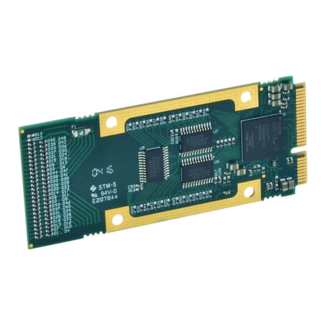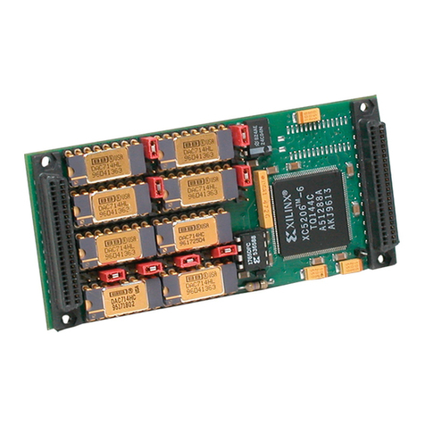
SERIES IOS-445 I/O SERVER MODULE 32 CHANNEL ISOLATED SSR OUTPUT MODULE
____________________________________________________ _____________________________________
-
-
Acromag,
Inc.
Tel:248-
295-0310 Fax:248-624-9234 Email:[email protected] http://www.acromag.com
4.0 THEORY OF OPERATION
This section contains information regarding the basic
functionality of the circuitry used on the IOS-445. Refer to the IOS-
445 BLOCK DIAGRAM located at the end of this manual as you
review this material.
OUTPUT PORTS
The field I/O interface to the carrier board is provided through
connector P2 (refer to Table 2.1). Individual Solid State Relays
(SSR‟s) for each channel isolate the field from the control logic for
the IOS-445. Channels are isolated from each other in groups of
eight. There are eight channels to a group or port. Because the
output lines of a single port share a common connection, individual
outputs are not isolated from each other within the same port.
However, separate port commons are provided to facilitate port-to-
port isolation.
32 Single Pole Single Throw - Normally Open (SPST-NO,
“1 Form A”) SSR outputs are controlled by this module. Each
group of eight channels can be connected directly to positive or
negative supplies for high (hot) side switching. Alternatively, each
group of eight channels can be connected to common for low side
switching. Socketed pull-up resistors are provided for low side
switching applications. These resistors should be removed if high
side switching is needed. In low side switching applications the
resistor values can be changed (e.g. lower values will provide a
faster pull-up while a higher values will keep power dissipation from
becoming a problem at higher voltages) - see Specifications in
Chapter 6 for details.
The SSR‟s are controlled by output registers within the FPGA.
Writing a „1‟ to the output register will turn the switch ON (closed-
circuit) while writing a „0‟ will turn it OFF (open-circuit). Readback
of the output state is accomplished by reading the output registers.
However, for complete confidence in output control, loopback
should be performed. This may be accomplished using the IOS-
440 isolated digital input module (refer to IOS-440/IOS-445
LOOPBACK CONNECTIONS).
The SSR‟s employed are rated for a much higher voltage than
specified. However, the field connector and printed circuit board
foil spacings limit applied voltages to +/-60VDC or AC peak. Each
port (group of eight channels) has a single common. Since the
connectors and cables are rated to 1A maximum per pin, then each
port is limited to that total current. Thus, the sum of currents
conducted by the 8 channels must stay below that total (see
specifications in Chapter 6 for details). The low on resistance of
the SSR‟s helps reduce their power dissipation when they conduct
high currents; however, given the large number of channels on the
board adequate air circulation must be maintained. The SSR‟s
used in the IOS-445 are very rugged and contain built-in current
limiting for their protection. They provide clean, bounce free
switching and can replace electromechanical relays in many
applications. SSR switching speeds are comparable to
electromechanical relays (1mS. typical) but are slow compared to
high speed optocouplers.
Output operation is “Fail-safe”. That is, the outputs are always
OFF upon power-up reset, and are automatically cleared following
a software (control register) or system software reset. This is done
for safety reasons to ensure reliable control of the output state
under all conditions.
5.0 SERVICE AND REPAIR
SERVICE AND REPAIR ASSISTANCE
Surface-Mounted Technology (SMT) boards are generally
difficult to repair. It is highly recommended that a non-functioning
board be returned to Acromag for repair. The board can be
damaged unless special SMT repair and service tools are used.
Further, Acromag has automated test equipment that thoroughly
checks the performance of each board. When a board is first
produced and when any repair is made, it is tested, placed in a
burn-in room at elevated temperature, and retested before
shipment.
Please refer to Acromag's Service Policy Bulletin or contact
Acromag for complete details on how to obtain parts and repair.
PRELIMINARY SERVICE PROCEDURE
Before beginning repair, be sure that all of the procedures in
Section 2, Preparation For Use, have been followed. Also, refer to
the documentation of your carrier board to verify that it is correctly
configured. Verify that there are no blown fuses. Replacement of
the carrier and/or IOS with one that is known to work correctly is a
good technique to isolate a faulty board.
CAUTION: POWER MUST BE TURNED OFF BEFORE
REMOVING OR INSERTING BOARDS
WHERE TO GET HELP
If you continue to have problems, your next step should be to
visit the Acromag worldwide web site at http://www.acromag.com.
Our web site contains the most up-to-date product and software
information.
Go to the “Support” tab to access:
Application Notes
Frequently Asked Questions (FAQ‟s)
Product Knowledge Base
Tutorials
Software Updates/Drivers
An email question can also be submitted from within the
Knowledge Base or directly from the “Contact Us” tab.
Acromag‟s application engineers can also be contacted directly
for technical assistance via telephone or FAX through the numbers
listed below. When needed, complete repair services are also
available.
Phone: 248-295-0310
Fax: 248-624-9234
Email: solutions@acromag.com


