ACS Alert J5 Use and care manual

Calibration manual
BREATH ALCOHOL TESTER


Alcohol Countermeasure Systems Corp
60 International Boulevard
Toronto, Ontario M9W 6J2 CANADA
T +1 416 619 3500
F +1 416 619 3501
acs-corp.com
ACS, ALCOHOL COUNTERMEASURE SYSTEMS, ALCOSIM, ALERT and the “Molly” are trademarks of
Alcohol Countermeasure Systems (International) Inc. and are used under license. Alcohol Countermeasure
Systems is the trading style of Alcohol Countermeasure Systems (International) Inc.
© 2013 - 2015 Alcohol Countermeasure Systems
The information disclosed in this document is the valuable property of Alcohol Countermeasure Systems and
all copyright and other proprietary rights to this document are reserved. No reproduction of this document is
permitted without the prior written consent of Alcohol Countermeasure Systems.

ALERT J5 HANDSET COMPONENTS
FRONT VIEW BACK VIEW
Left
navigational
button
Right
navigational
button
Red
plastic tab
Battery
cover
Main
button
Exhaust grid
BOTTOM VIEWTOP VIEW
USB port
Mouthpiece
port
Graphic display

TABLE OF CONTENTS
Safety and precautions................................................................................................ 1
General.................................................................................................................... 1
Compressed gas safety........................................................................................... 1
ALCOSIM setup, usage and disassembly............................................................... 1
Alcohol reference solution....................................................................................... 2
Cleaning the ALCOSIM breath alcohol simulator.................................................... 3
Calibration types .......................................................................................................... 3
Gas standard calibration ............................................................................................. 3
Calibration materials................................................................................................ 3
Dry gas calibration process..................................................................................... 3
Alcohol Reference Standard (ARS) calibration ......................................................... 6
Calibration materials................................................................................................ 6
ALCOSIM breath alcohol simulator – overview....................................................... 7
Parts diagram................................................................................................... 7
Kit connection diagram..................................................................................... 8
Alcohol reference solution – overview..................................................................... 8
ALCOSIM setup and operation steps...................................................................... 9
ARS calibration process.......................................................................................... 9
Troubleshooting ......................................................................................................... 10

ALERT J51
SAFETY AND PRECAUTIONS
WARNING! Failure to comply with the warnings and precautions in this manual
may cause personal injury, product damage, voiding of product warranty or a
failed calibration.
GENERAL
•The ALCOSIM breath alcohol simulator is intended for authorized technicians only
•Use the ALCOSIM simulator for its intended purpose only
•Use parts specied by ACS only
•Before use, check that the simulator power supply rating (24Vdc, 2.5A) conforms to
local supply ratings
•Do not disassemble product, except as specied
•Do not attempt to repair product; you must contact an authorized service provider
•It is recommended that calibration be done indoors, in a service facility
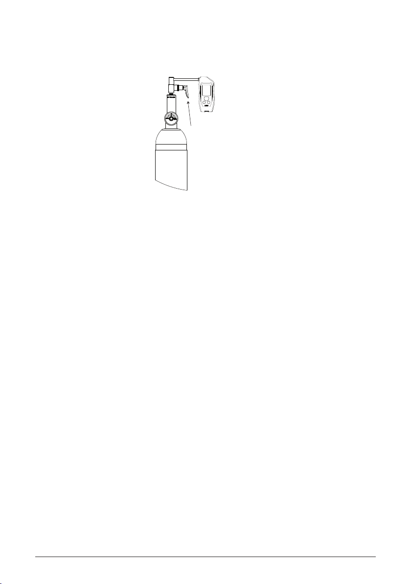
COMPRESSED GAS SAFETY
•Damaged or broken valves can turn a canister into a dangerous projectile. Attach
the valve in a safe location
•Calibration should be performed indoors, in a service facility, where the gas
standard cylinder can be properly stored
•Transportation and storage of compressed gases in vehicles is dangerous and
should be avoided
•Examine the canister and valve for any damage; pay close attention to the
expiration date on the label
•Observe all cautions and safety warnings found on the canister
•Never remove or alter canister labels
•Never modify the delivery tubing in any way
•Always remove the valve and install the protective cap on cylinders when not in use
•Store cylinders in a cool, well ventilated area, away from sources of heat
ALCOSIM SETUP, USAGE AND DISASSEMBLY
•CAUTION! When assembling, disassembling or preparing the ALCOSIM breath
alcohol simulator for use, ensure that it is not plugged into an electrical outlet
•CAUTION! Hot surface – avoid contact with the heating element
•Place the ALCOSIM simulator on a at surface, free from obstruction
•Do not expose the simulator to direct sunlight for extended periods of time
•Do not use the simulator with any toxic or ammable liquids, or in explosive
atmospheres

CALIBRATION MANUAL 2
•Recommended: Use the simulator within room temperature environments
(23 °C ± 2 °C and approx. 50% RH)
•The solution container, tubing and mouthpieces must be completely dry; even slight
condensation may disrupt calibration
•Fit tubing on an aquarium air pump or a similar setup for drying
•CAUTION! Never connect the simulator to an electrical outlet without rst adding
solution and attaching the top housing
•The simulator requires 500 mL of solution; the ll line is marked on the simulator
container
•Do not under or over ll the simulator container
•Do not over tighten the top housing
•Connect the simulator cables neatly to ensure simple disconnection after use
•Do not force a misaligned cable connector into place
•If solution overheats considerably beyond 34 °C, disconnect the simulator power
immediately
•Disconnect the simulator power after use
•CAUTION! After disconnecting the simulator power, allow 10 to 15 minutes for the
heating element to cool before detaching the top housing
•Empty out the solution container at the end of a work day
•Store the simulator in an environment of 5 to 40 °C and 10 to 85% RH
ALCOHOL REFERENCE SOLUTION
•Use the solution concentration specied in the manual for breath testing devices
•Replace solution every 5 days or 20 tests
•Use of solution over time affects alcohol concentration
•Do not use a solution bottle with a broken seal, or an expired bottle
•Never use articial methods to reheat or cool solution, or the solution container
•Keep solution at room temperature
•Do not freeze or refrigerate solution
•Do not ingest solution
•Keep solution away from eyes
•If solution comes in contact with eyes, ush eyes with water; if irritation continues,
contact your local poison control centre
•Refer to your local environmental regulations for more information about safe
solution-disposal amounts

ALERT J53
CLEANING THE ALCOSIM BREATH ALCOHOL SIMULATOR
•Disconnect the ALCOSIM breath alcohol simulator power before cleaning
•CAUTION! After disconnecting the ALCOSIM simulator power, allow 10 to 15
minutes for the heating element to cool off before detaching the top housing
•Do not submerge the top housing in water
•Clean the top housing by wiping with a water dampened cloth
•Wash the solution container with plain water and dry with paper towel
CALIBRATION TYPES
There are 2 methods of calibration for the ALERT J5 breath alcohol tester:
•Gas Standard, which uses a gas standard cylinder. See “Gas Standard Calibration”
•Alcohol Reference Standard (ARS), which uses at least 2 ALCOSIM breath alcohol
simulators. See “Alcohol Reference Standard (ARS) Calibration”
4 tests are required to ensure proper calibration. The rst cycle starts the calibration
and subsequent cycles are used to ensure that the same threshold is met.
GAS STANDARD CALIBRATION
CALIBRATION MATERIALS
•105 L, 260PPM cylinder of gas standard (100 mg/dL),
ACS #95-000430
•Regulator valve assembly (6 L/min ow rate): ACS #94-000225 (trigger);
ACS #94-000226 (push button)
DRY GAS CALIBRATION PROCESS

CALIBRATION MANUAL 4
1. Remove the protective cap of the canister and screw on the regulator valve
assembly.
2. Attach the delivery tubing to the regulator valve.
3. Press the main button to power on the ALERT J5 tester.
4. In the main menu, scroll to the Settings icon with the navigation buttons and press
the main button to select. Scroll to the Device Settings icon with the navigation
buttons and select with the main button. Scroll to the entry labelled PCB serial
number.
The last 4 digits of the PCB serial number will be used as a password for the next
step.
5. In the main menu, scroll to the Troubleshooting icon with the navigation buttons
and select with the main button. Scroll to the Advanced option with the navigation
buttons and select with the main button.
The password eld will ash on the display. Enter the password with the navigation
buttons and enter with the main button. Select OK with the main button to conrm.
6. The current screen displays the different calibration types. Scroll to Dry Gas with
the navigation buttons and select with the main button.
NOTE: You must input the altitude prior to a gas standard calibration. Check
the altitude of your exact location online.
7. Wait until the tester returns to Ready and displays CALIBRATION ST.1. The
number indicates the sample number you are providing.
4 samples are required to calibrate this device.
8. Attach the delivery tubing to the mouthpiece port of the tester. Hold the tester in
place for the next step.

ALERT J55
9. Press and hold the regulator valve down to release the gas while still holding the
tester. A tone will be heard.
10. Release the regulator valve when the tone ends and the results are displayed.
11. Repeat the calibration process as indicated by the device (4 times total).
When the test is accepted and the calibration is completed, CALIBRATION DONE
will be displayed.
NOTE: If the calibration fails on numerous attempts, the sensor may need to
be replaced. Contact an authorized service provider for return instructions.
Hold handset
Press valve

CALIBRATION MANUAL 6
ALCOHOL REFERENCE STANDARD (ARS)
CALIBRATION
CALIBRATION MATERIALS
•Alcohol Reference Solution, 100 mg% ACS #95-000310
•ALCOSIM kit (includes the ALCOSIM breath alcohol simulator and all accessories):
- Australian kit ACS #94-001200
- UK kit ACS #94-001210
- European kit ACS #90-001220
- North American kit ACS #94-001230
- Japanese kit ACS #94-001240
- Brazilian kit ACS #94-001250
•ALCOSIM kit contents include:
- ALCOSIM breath alcohol simulator ACS #79-007600
- AC power cord: Part number depends on your region
- Power supply (24Vdc, 2.5A) ACS #07-000075
- 1.5 feet of vinyl tubing ACS #70-000002
- Square mouthpiece ACS #95-000121
- Round mouthpiece ACS #95-000250

ALERT J57
ALCOSIM BREATH ALCOHOL SIMULATOR – OVERVIEW
At least 2 ALCOSIM simulators must be used to properly calibrate the ALERT J5.
PARTS DIAGRAM
BACK
Optional
thermometer port
24V power input
Communication
port
Solution
container
Top housing

CALIBRATION MANUAL 8
KIT CONNECTION DIAGRAM
ALCOHOL REFERENCE SOLUTION – OVERVIEW
2 bottles of 100 mg% solution must be used to properly calibrate the
ALERT J5. The ARS solution is:
•Supplied in 500 mL tamper-sealed bottles
•Premixed and ready for immediate use with the ALCOSIM simulator
For availability, pricing and ordering, contact your local authorized
service provider or visit acs-corp.com.
(A)
(D)
(C)
(B2)
(B3)
(B1)
A Round mouthpiece (for manually blowing into the simulator)
B1, B2, B3 Vinyl tubing (cut to size by a technician)
CSquare mouthpiece (connects to a breath tester)
D Power cord

ALERT J59
ALCOSIM SETUP AND OPERATION STEPS
1. With both ALCOSIM breath alcohol simulators power disconnected, turn the top
housings counter clockwise and detach them from each container.
2. Add the entire contents of a 500 mL bottle of 100 mg% alcohol reference solution
into each ALCOSIM solution container.
Each bottle contains the exact liquid volume required for calibration, which is also
marked on each ALCOSIM container.
3. Return the top housings onto each container; be careful not to over tighten.
4. Connect vinyl tubing with the round mouthpiece to the rst ALCOSIM simulator air
inlet and another piece of tubing to the vapor outlet. Connect the piece of tubing
from the vapor outlet of the rst simulator to the air inlet of the second. Place
another piece of tubing with a square mouthpiece to the vapor outlet of the second
simulator.
5. Perform a leak check by blocking the open end of the square mouthpiece with your
thumb and blowing into the round mouthpiece.
Air bubbles should not appear in the solution. In case of bubbling, refer to the
“Troubleshooting” section in this manual.
6. Connect the power cable to each simulator power input and to a wall outlet.
7. Switch on each simulator. The following occurs:
•Each LCD display illuminates
•The propellers rotate and each heating element activates
•Cold is displayed until solution reaches 32 ºC, wherein the LCD screens display
actual solution temperature
•Each simulator maintains solution at a constant 34 ºC ± 0.2 ºC
Solution heat-up takes about 10 minutes. When 34 ºC ± 0.2 ºC is displayed, the
simulators are ready to provide a breath sample.
ARS CALIBRATION PROCESS
1. Press the main button to power on the ALERT J5 tester.
2. In the main menu, scroll to the Settings icon with the navigation buttons and press
the main button to select. Scroll to the Device Settings icon with the navigation
buttons and select with the main button. Scroll to the entry labelled PCB serial
number.

CALIBRATION MANUAL 10
The last 4 digits of the PCB serial number will be used as a password for the next
step.
3. In the main menu, scroll to the Troubleshooting icon with the navigation buttons
and select with the main button. Scroll to the Advanced option with the navigation
buttons and select with the main button.
The password eld will ash on the display. Enter the password with the navigation
buttons and enter with the main button. Select OK with the main button to conrm.
4. The current screen displays the different calibration types. Scroll to Wet
Calibration with the navigation buttons and select with the main button.
5. Wait until the tester returns to Ready and displays CALIBRATION ST.1. The
number indicates the sample number you are providing.
4 samples are required to calibrate the device.
6. Insert the tip of the square mouthpiece from the simulator into the sensor inlet of
the tester.
7. Blow into the round mouthpiece of the simulator. Keep blowing until the tone ends
and the results are displayed. The tester will emit a tone to indicate proper breath
ow.
8. Repeat the calibration process as indicated by the device (4 times total).
When the test is accepted and the calibration is completed, CALIBRATION DONE
will be displayed.
NOTE: If the calibration fails on numerous attempts, the sensor may need to
be replaced. Contact an authorized service provider for return instructions.
TROUBLESHOOTING
In the event of a calibration failure using the ALCOSIM simulator, consult the
“Troubleshooting — Error Codes” section of the ALCOSIM Breath Alcohol Simulator
Instruction Manual (ACS #60-000180).
If a calibration fails while using a gas standard cylinder, it may be due to the following:
•Vinyl tubing has been overused or condensation is present
•The gas standard cylinder is expired or is empty
•Connections to and from the gas valve are not secured properly

CAM-ENG-60-000633-B
© 2013 - 2015
Other manuals for Alert J5
3
Table of contents
Other ACS Test Equipment manuals

ACS
ACS ALERT J4X User manual

ACS
ACS ALCOLOCK LR Programming manual

ACS
ACS UK1401 User manual

ACS
ACS ALCOSIM User manual

ACS
ACS Alert J5 User manual

ACS
ACS Alcocheck User manual

ACS
ACS A1212 MASTER User manual

ACS
ACS A1208 User manual

ACS
ACS DRIVESAFE Use and care manual

ACS
ACS ALCOHOL INTERLOCK V3 User manual

ACS
ACS ALERT J4X.ec User manual

ACS
ACS Alcolock L OEM User manual

ACS
ACS ALCOCHECK Use and care manual

ACS
ACS ALCOLOCK V3 B-2 WI-FI Series User manual

ACS
ACS ALCOLOCK V3 B-2 WI-FI Series Use and care manual

ACS
ACS ALCOSENTRY User manual

ACS
ACS Alert J5 User manual

ACS
ACS DRIVESAFE User manual

ACS
ACS ALCOLOCK B-2 Series Use and care manual

ACS
ACS WR3 User manual