manuals.online logo
Brands
  1. Home
  2. •
  3. Brands
  4. •
  5. ADC
  6. •
  7. Medical Equipment
  8. •
  9. ADC Diagnostix 2100 Manual

ADC Diagnostix 2100 Manual

ADC®Diagnostix™ 2100 Fingertip
Pulse Oximeter
Directions for use
®
ADC® Fingertip Pulse Oxi eter
Thank you for purchasing an ADC DiagnostixTM Brand Fing rtip Puls Oxim t r. W ’r proud of th car
and quality that go s into th manufactur of v ry product that b ars our nam . With prop r car and
maint nanc your DiagnostixTM Fing rtip Puls Oxim t r will provid many y ars of d p ndabl s rvic .
Device Description and Intended Use
This d vic is int nd d for m dical diagnostic purpos s only. It is us d to indir ctly m asur th func-
tional oxyg n saturation (SpO2) of an adult or p diatric pati nt’s blood. It is int nd d for us on fing rs
with a thickn ss of 8mm-20mm (.31”-.79”). This is th distanc b tw n th fing rnail (top), and th
fing r pad (bottom). Functional oxyg n saturation r f rs to th ratio of oxyh moglobin to all h moglobin
that is capabl of carrying oxyg n. This oxim t r is not int nd d for continuous monitoring. Th Puls
Oxim t r r quir s no routin calibration or maint nanc oth r than r plac m nt of batt ri s.
Puls oxim try combin s th principl s of optical pl thysmography and sp ctrophotom try to
d t rmin art rial oxyg n saturation valu s. Optical pl thysmography us s light absorbanc t chnol-
ogy to r produc wav forms produc d by pulsating blood. Sp ctrophotom try us s various wav -
l ngths of light to p rform quantitativ m asur m nts about light absorption. Photo l ctric
Oxyh moglobin Insp ction T chnology is combin d with Capacity Puls Scanning and R cording
T chnology, so that two b ams of diff r nt wav l ngths of light (660nm glow and 940nm n ar in-
frar d light) can b focus d onto th human nail tip through a fing r-tip s nsor. Th s two LED’s ar
chos n b caus th light absorption vari s with th oxyg n conc ntration of h moglobin in th s fr -
qu nci s. Th puls amplitud s of th r d and n ar infrar d signals ar d t ct d using photo l ctric
s nsors and run through a microproc ssor which conv rts th r adings to num rical valu s.
Contraindications:
Th pati nt suff rs from significant l v ls of dysfunctional h moglobins (such as carbonxy-•
h moglobin or m th moglobin).
Intravascular dy s such as indocyanin gr n or m thyl n blu hav b n inj ct d into th•
pati nt.
Us d in th pr s nc of high ambi nt light (i , dir ct sunlight). Shi ld th s nsor ar a with a•
surgical tow l if n c ssary.
Th r is xc ssiv pati nt mov m nt.•
Th pati nt xp ri nc s v nous pulsations.•
Th pati nt has hypot nsion, s v r vasoconstriction, s v r an mia, or hypoth rmia.•
Th pati nt is in cardiac arr st or is in shock.•
Pati nts hav fing rnail polish or fals fing rnails as th y may caus inaccurat SpO2 r adings.•
General Warnings
A warning stat m nt in this manual id ntifi s a condition or practic which, if not corr ct d or dis-
continu d imm diat ly, could l ad to pati nt injury, illn ss, or d ath.
WARNING: B for us , car fully r ad th manual.
WARNING: Do not us th puls oxim t r in an MRI or CT nvironm nt.
WARNING: Th op ration of Puls Oxim t r may b aff ct d by th us of an l ctrosurgical unit (ESU).
WARNING: F d ral law r stricts this d vic to sal by or on th ord r of a physician or lic ns d
h althcar practition r.
WARNING: Th puls oxim t r is int nd d only as an adjunct in pati nt ass ssm nt. It must b us d in
conjunction with oth r m thods of ass ssing clinical signs and symptoms.
WARNING: Follow local ordinanc s and r cycling instructions r garding disposal or r cycling of
th d vic and d vic compon nts, including batt ri s.
WARNING: This product may contain a ch mical known to th stat of California to caus canc r,
birth d f cts, or oth r r productiv harm.
CAUTION: Do not use the pulse oxi eter in an explosive at osphere.
CAUTION: SpO2 and puls rat data is display d for informational purpos s only and do s not con-
stitut a diagnosis or m dical advic of any kind. Only a qualifi d h althcar prof ssional should in-
t rpr t th data obtain d on this d vic .
CAUTION: Ch ck th puls oxim t r s nsor application sit fr qu ntly to d t rmin th positioning
of th s nsor and circulation and skin s nsitivity of th pati nt.
CAUTION: Th puls oxim t r is not for continuous monitoring.
CAUTION: Prolong d us or th pati nt's condition may r quir changing th s nsor sit p riodically.
Chang s nsor sit and ch ck skin int grity, circulatory status, and corr ct alignm nt at l ast v ry 4 hours.
CAUTION: Inaccurat m asur m nts may b caus d by autoclaving, thyl n oxid st rilizing, or im-
m rsing th s nsors in liquid.
CAUTION: Th d vic should not b us d on an xtr mity with a blood pr ssur cuff, art rial
cath t r, or intravascular lin .
Brief Description of Front Panel
Included Pulse Oxi eter Accessories
• On (1) lanyard
• Two (2) AAA batt ri s
• On (1) us r manual
Battery Installation
1. R mov batt ry compartm nt cov r by d -•
pr ssing button on batt ry cov r top, th n
slid cov r in th dir ction of th arrow, th n
tilt upward on hing .
2. Ins rt two AAA batt ri s into batt ry com-•
partm nt b ing sur to obs rv th corr ct po-
lariti s.
3. R plac th batt ry cov r by r v rsing st p•
1. (Figur 1)
Note: Be sure to observe correct battery polar-
ity. Failure to do so might damage the device. If
device will not be used for an e tended period of time, remove batteries. Replace batteries
when low battery symbol appears on display. Always replace BOTH batteries at the same time.
SpO2
Pulse Rate Signal
Intensity Bar Graph
Pulse Rate
Power Switch
Low Power
Indicator
SpO2
Waveform
(Figur 1)
Operating Instructions
B sur to ins rt two AAA batt ri s b for at-1.
t mpting to op rat .
Cl an insid surfac of oxim t r and pati nt’s2.
fing r with isopropyl alcohol b for us .
Squ z th nd opposit th pow r switch b -3.
tw n th thumb and for fing r in ord r to op n
th d vic (th r is a t xtur d surfac on th bat-
t ry cov r sid to facilitat grip). (Figur 2)
Ins rt pati nt’s fing r, nail sid up into th d -4.
vic . (b sur to fully ins rt th pati nt’s fing r so that th s nsors ar compl t ly cov r d by th fin-
g r.) Ind x or middl fing r is r comm nd d.
R l as th d vic allowing it to clamp down on th pati nt’s fing r.5.
Pr ss th pow r switch on th front (top) pan l to activat .6.
Hav pati nt k p still for optimal accuracy 7.
D p nding upon nvironm ntal and pati nt conditions, th d vic will b gin to display r adings in8.
about 4 s conds.
Not r adings on th display.9.
R mov th pati nt’s fing r from th d vic by squ zing b tw n for fing r and thumb as indicat d10.
in Figur 2.
Th display will indicat fing r out.11.
Th unit will pow r off approximat ly 10 s conds aft r th pati nt’s fing r is r mov d from th d vic .12.
Changing Oxi eter Display Mode
Th r ar six diff r nt display mod s. Th display mod s alt r th ori ntation of th display to facilitat
r ading by th obs rv r. Horizontal mod s display th puls wav form along with SPO2 and puls rat
whil v rtical mod s display a puls rat bar graph along with th SPO2 and puls rat r adings.
To alter the display ode:
1. Aft r th unit is pow r d on ach bri f pr ss of th pow r switch will cycl through to th n xt
display mod in th s qu nc shown. Note: th d fault s tting is display mod 1.
Display Mode Cycle
(Figur 2)
Handstand Horizontal
(4th click)
Pulse Tone Active
Alarm Tone Active
Normal V rtical
(5th click)
Pulse Tone Active
Alarm Tone Active
Handstand V rtical
(6th click)
Pulse Tone Active
Alarm Tone Active
Normal Horizontal
Wav Display
(D fault S tting)
No Pulse Tone
Alarm Tone Active
Normal Horizontal
Wir Display
(2nd click)
Pulse Tone Active
Alarm Tone Active
Normal Horizontal
(3rd click)
Pulse Tone Active
Alarm Tone Active
Alar
On mod ls quipp d with an alarm, th alarm condition will app ar wh n:
SPO2 < 90% / PR <60 or >100bpm
If th unit is in display mod 1 (sil nt mod ), th param t r (SPO or PR) flash s and an audibl
b p is h ard if it xc ds th alarm condition. If th unit is in display mod s 2-6 (audibl mod ),
th unit will signal an alarm condition with both visual and audibl al rts.
Note: Th alarm can b d activat d for 30 s conds by pr ssing th pow r button onc .
Note: This d vic is not int nd d for continuous pati nt monitoring. Alarm sounds ar for
r f r nc purpos s only.
Changing the Display Brightness (10 adjustable brightness settings)
To change the brightness setting:
1. Aft r th unit is pow r d on, hold and d pr ss th pow r switch. It will cycl
through from BR4 up to BR10, th n start back at BR1.
Note: Th d fault s tting is l v l 4 (BR4).
Lanyard Attach ent
1. Thr ad thinn r nd of th lanyard through th hanging hol at th r ar nd of th d vic .
2. Thr ad thick r nd of th lanyard through th thr ad d nd b for pulling it tightly.
Care and Maintenance
1. R plac th batt ri s promptly wh n low voltag indicator app ars.
2. Cl an surfac of th fing rtip and oxim t r with isopropyl alcohol b for it is us d in
diagnosis for pati nts.
3. R mov th batt ri s if unit will not b op rat d for xt nd d p riod of tim .
4. It is b st to stor this product in a plac wh r ambi nt t mp ratur is -10°C -40°C
(14°F -104°F) and humidity is 10%-80%.
5. It is r comm nd d that th product should b k pt in a dry nvironm nt at all tim s.
6. Pl as follow local ordinanc s wh n disposing of batt ri s.
Cleaning the Pulse Oxi eter
Cl an th rubb r touching th fing r insid of th Oxim t r with a soft damp n d cloth with 70%
isopropyl alcohol, and cl an th t st fing r using alcohol b for and aft r ach t st.
Note: Do not pour or spray any liquids onto th Oxim t r, and do not allow any liquids to nt r any
op nings in th d vic . Allow th Oxim t r to dry thoroughly b for r using.
Troubleshooting Possible Proble s
Proble
SpO2% or puls rat do not display
normally.
SpO2% or puls rat is shown un-
stably.
Possible Reason
1. Fing r is not ins rt d corr ctly.
2. Pati nt SpO2 valu is too low
to b m asur d.
1. Fing r might not b ins rt d
d p nough.
2. Exc ssiv pati nt mov m nt.
Solution
1. R try ins rting th fing r.
2. Th r is xc ssiv illumination.
3. M asur mor tim s. If you d t rmin th
product is working corr ctly, s your h alth-
car provid r for an xact diagnosis.
1. R try ins rting th fing r.
2. Sit calmly and r try.
Th monitor cannot b pow r d
on.
Indication is sudd nly off.
“Err 3” or “Err 4”
“Err 6”
“Err 7”
1. No batt ry or low batt ry
pow r.
2. Batt ry not install d corr ctly.
3. Th monitor may b damag d.
1. Th Oxim t r is automatically
pow r d off, wh n no signal was
d t ct d aft r 8 s conds.
2. Th batt ry pow r is too low to
op rat .
1. ERR 3 m ans th r d mission
LED is damag d.
2. Err 4 m ans th infra-r d
mission LED is damag d.
Err 6 m ans crystal damag .
Err 7 m ans all th mission LED
or r c ption dioxid is damag d.
1. R plac batt ry.
2. R mov and r install batt ry.
3. Contact custom r s rvic c nt r.
1. Normal.
2. R plac batt ri s.
1. Ch ck th r d mission LED.
2. Ch ck th infra-r d mission LED.
3. R turn to S rvic C nt r
1. R turn to S rvic C nt r
Guidance and Manufacturer’s Declaration: Electro agnetic E issions
Guidanc and Manufactur r’s d claration - l ctromagn tic nvironm nt sp cifi d b low.
Th custom r or th us r of th PULSE OXIMETER should assur that it is us d in such an nvironm nt.
E ission Test
RF Emissions CISPR11
Harmonic missions
IEC 61000-3-2
Voltag fluctuations/
Flick r missions
IEC 61000-3-2
Co pliance Level
Group 1
Class B
Not applicabl
Not applicabl
Electronic Environ ent Guidance
Th PULSE OXIMETER us s v ry low RF n rgy
only and is not lik ly to caus int rf r nc to n arby
l ctronic quipm nt.
Th PULSE OXIMETER is suitabl for us in all s-
tablishm nts,including dom stic and thos dir ctly
conn ct d to th public low-voltag pow r supply
which pow rs buildings us d for dom stic pur-
pos s.
I unity
Test
El ctrostatic Dis-
charg (ESD)
IEC 61000-4-2
Pow r Fr qu ncy
(50/60 Hz) Mag-
n tic Fi ld
IEC 61000-4-8
IEC 60601
Test Level
+/- kV contact
+/- 8kV air
3A/m
Co pliance
Level
+/- kV Contact
+/- 8kV air
3A/m
Guidance and Manufacturer’s Declaration - Electro agnetic I unity
For all Equip ent and Syste s
Guidanc and Manufactur r’s d claration - l ctromagn tic nvironm nt sp cifi d b low.
Th custom r or th us r of th PULSE OXIMETER should assur that it is us d in such an nvironm nt.
Electronic Environ ent
Guidance
Floors should b wood, concr t , or c ramic til .
If floor is cov r d with synth tic mat rial, th r la-
tiv humidity should b at l ast 30%.
Pow r fr qu ncy magn tic fi lds should b at l v-
ls charact ristic of a typical location in a typical
comm rcial or hospital nvironm nt.
Reco ended Separation Distance Between Portable and Mobile RF
co unication equip ent and the Equip ent or Syste s
For all equip ent and Syste s that are not Life-Supporting -- Reco ended separation distances
between portable and obile RF co unications equip ent and Pulse Oxi eter
Th Puls Oxim t r is int nd d for us in l ctromagn tic nvironm nt in which radiat d RF disturbanc s ar
controll d. Th custom r or th us r of th Puls Oxim t r can h lp pr v nt l ctromagn tic int r f r nc by
maintaining a minimum distanc b tw n portabl and r comm nd d b low, according to th maximum out-
put pow r of th communications quipm nt.
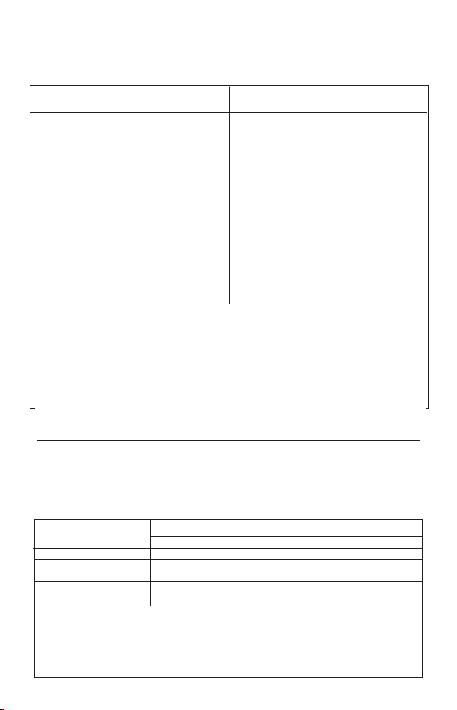
Rated axi u Output
power of trans itter (W)
Separation distance according to frequency of trans itter ( )
For transmitt rs rat d at a maximum output pow r not list d abov , th r comm nd d s partaion distanc (d) in m t rs (m)
can b stimat d using th quation applicabl to th fr qu ncy of th transmitt r, wh r (p) is th maximum output pow r
rating of th transmitt r in watts (w) according to th transmitt r manufactur r.
NOTE 1: At 80 MHz and 800 MHz, th s paration distanc for th high r fr qu ncy rang appli s.
NOTE 2: Th s guid lin s may not apply in all situations. El ctromagn tic propagation is aff ct d by absorption
and r fl ction from structur s, obj cts, and p opl .
I unity
Test
Radiat d RF
IEC 61000-4-3
IEC 60601
Test Level
3 V/m
80 MHz to 2.5 GHz
Co pliance
Level
3 V/m
Guidance and Manufacturer’s Declaration - Electro agnetic I unity
For all Equip ent and Syste s that are not Life-Supporting
Guidanc and Manufactur r’s d claration - l ctromagn tic nvironm nt sp cifi d b low.
Th custom r or th us r of th PULSE OXIMETER should assur that it is us d in such an nvironm nt.
Electronic
Environ ent Guidance
Portabl and mobil RF communications quipm nt should not
b us d clos to any part of th Puls Oxim t r, including cabl s.
Th r comm nd d s paration distanc should b calculat d
from th quation applicabl to th fr qu ncy of th transmitt r.
R comm nd d s paration distanc
80MHZ to 800MHZ
800MHZ to 2.5GHz
Wh r P is maximum output pow r rating of th transmitt r
in watts (W) according to th transmitt r manufactur r and (d) is
th r comm nd d s paration distanc in m t rs (m).
Wh r P is th maximum output pow r rating of th transmitt r in
watts (W) according to th transmitt r manufactur r and d is th
r comm nd d s paration distanc in m t rs (m).
Fi ld str ngths from fix d RF transmitt rs, as d t rmin d by an
l ctromagn tic sit surv y. should b l ss than th complianc
l v l in ach fr qu ncy rang .
NOTE 1: At 80MHz and 800MHz, th high r fr qu ncy rang appli s.
NOTE 2: Th s guid lin s may not apply in all situations. El ctromagn tic propagation is aff ct d by absorption and
r fl ction structur s, obj cts and p opl .
A. Fi ld str ngths from fix d transmitt rs, such as bas stations for radio, (c llular/cordl ss) t l phon s, and land mobil radios,
amat ur radio, AM/FM radio, and TV broadcasts cannot b pr dict d th or tically with accuracy. To ass ss th l ctromagn tic
nvironm nt du to fix d RF transmitt rs, an l ctromagn tic sit surv y should b consid r d. If m asur d fi ld str ngth in th
location in which th Puls Oxim t r should b obs rv d to v rify normal op ration. If abnormal p rformanc is obs rv d, ad-
ditional m asur m nts may b n c ssary, such as r ori nting th location of th Puls Oxim t r.
B.Ov r th fr qu ncy rang 150kHz to 80MHz, fi ld str ngths should b l ss than 3V/m.
80 MHz to 800 MHz 800 MHz to 2.5 GHz
0.01 0.1167 0.2334
0.1 0.3689 0.7378
1 1.1667 2.3334
10 3.6893 7.3786
100 11.6667 23.3334
Technical Specifications
Display Typ : OLED Display
SPO2 display rang : 0-100%
PR Display Rang : 30-235 BPM
PR Display Mod : Bargraph
Data Updat Tim : < 15 s
LED Wavelengths
R d: 660nm
Infrar d: 940nm
Measure ent range:
SPO2: 70-99% - 100% ±3%; s ≤70%
no d finition
Puls Rat : 30-235 BPM, ±2 bpm during th
puls rat rang of 30-99 bpm
and 2% during th puls rat
rang of 100-235 bpm.
Accuracy: ±2% on th stag of 80%-99%;
±3% on th stag of 70%-80%;
Accuracy: ±2 BPM or ±2% (larg r)
Puls Int nsity: Bargraph Indicator
Pow r R quir m nts: Two AAA alkalin Batt ri s
Pow r consumption: L ss than 40mA
Low power indication:
Batt ry Lif : (2) ”AAA” 1.5V, 600mAh alkalin batt ri s
Can op rat as long as 30 hours (continious).
Di ension:
L ngth: 2.3” (58mm)
Width: 1.3” (32mm)
H ight: 1.3” (34mm)
W ight: 1.8oz. (50g)
(including two AAA batt ri s)
Environ ent:
Op ration T mp ratur : 41°F - 104°F (5°C - 40°C)
Storag T mp ratur : 14°F - 104°F (-10°C - 40°C)
R lativ Humidty: 15%-80% in op ration /10%-80% in storag
Fing r Rang : 8mm-20mm (.31”-.79”)
Minimum W ight: 20lbs. (13kg)
Sy bol Definitions
Sy bol Definition
Important Warning/Caution
Lat x-Fr
Equipm nt typ is BF
H moglobin Saturation
H art Rat (BPM)
Low Pow r Indication
Not for Continuous Monitoring
Conforms to EU Standards
Authoriz d Europ an R pr s nativ ’s Information
Manufactur r’s Information
S rial Numb r
D claration: EMC of this product comply with IEC60601-1-2 standard.
M asur m nt P rformanc in Low P rfusion Condition: r quir d th t st quipm nt (BIO-
TEK INDEX Puls Oxim t r t st r) th puls wav is availabl without failur wh n th simu-
lation puls wav amplitud is at 6%.
Int rf r nc R sistanc Capacity against Ambi nt Light: D vic work normally wh n mix d
nois produc d by BIO-TEK INDEX Puls Oxim t r t st r.
Warranty
Am rican Diagnostic Corporation (ADC®) warrants its products against d f cts in mat rials and
workmanship und r normal us and s rvic as follows:
1. Warranty s rvic xt nds to th original r tail purchas r only and comm nc s with th dat
of d liv ry.
2. Your Puls Oxim t r is warrant d for two (2) y ars from dat of purchas (all parts).
What is Covered: R plac m nt of parts, and labor.
What is Not Covered: Transportation charg s to and from ADC®. Damag s caus d by abus ,
misus , accid nt, or n glig nc . Incid ntal, sp cial, or cons qu ntial damag s. Som stat s
do not allow th xclusion or limitation of incid ntal, sp cial, or cons qu ntial damag s, so
this limitation may not apply to you.
ADC
55 Commerce Drive
Hauppauge, NY 11788
U.S.A.
ADC (UK) Ltd.
Unit 6, PO14 1TH
United Kingdom
Inspected in the U.S.A.
Made in China
tel: 631 273 9600, 1 800 232 2670
fax: 631 273 9659
www.adctoday.com
email: info@adctoday.com
IB p/n 93 2100 00 rev 7 english
To Obtain Warranty Service: S nd it m(s) postag paid to ADC®, Attn: R pair D pt., 55
Comm rc Dr., Hauppaug , NY 11788. Pl as includ your nam and addr ss, phon no.,
proof of purchas , and a bri f not xplaining th probl m.
I plied Warranty: Any impli d warranty shall b limit d in duration to th t rms of this
warranty and in no cas b yond th original s lling pric ( xc pt wh r prohibit d by law).
This warranty giv s you sp cific l gal rights and you may hav oth r rights which vary from
stat to stat .

Other manuals for Diagnostix 2100

3

Other ADC Medical Equipment manuals

ADC PG-PLUS PLL-734 User manual

ADC

ADC PG-PLUS PLL-734 User manual

ADC Diagnostix 752M User manual

ADC

ADC Diagnostix 752M User manual

ADC Advantage 2200 Manual

ADC

ADC Advantage 2200 Manual

ADC Adscope Sprague Maintenance manual

ADC

ADC Adscope Sprague Maintenance manual

ADC ADView 2 9005BPSTO User manual

ADC

ADC ADView 2 9005BPSTO User manual

ADC Adscope Sprague Maintenance manual

ADC

ADC Adscope Sprague Maintenance manual

ADC Diagnostix 750W User manual

ADC

ADC Diagnostix 750W User manual

ADC Diagnostix 2100 Manual

ADC

ADC Diagnostix 2100 Manual

ADC Adscope Stethoscope 600 User manual

ADC

ADC Adscope Stethoscope 600 User manual

ADC Adscope 600 User manual

ADC

ADC Adscope 600 User manual

ADC Adscope 641 Sprague Maintenance manual

ADC

ADC Adscope 641 Sprague Maintenance manual

ADC Dermascope Maintenance manual

ADC

ADC Dermascope Maintenance manual

ADC DIAGNOSTIX 922 series Instruction Manual

ADC

ADC DIAGNOSTIX 922 series Instruction Manual

ADC Diagnostix ADSTATION User manual

ADC

ADC Diagnostix ADSTATION User manual

ADC Diagnostix 752M User manual

ADC

ADC Diagnostix 752M User manual

ADC Satin Mac 0 Manual

ADC

ADC Satin Mac 0 Manual

ADC DIAGNOSTIX 972 Maintenance manual

ADC

ADC DIAGNOSTIX 972 Maintenance manual

ADC Satin Mac 0 User manual

ADC

ADC Satin Mac 0 User manual

ADC e-sphyg 3 User manual

ADC

ADC e-sphyg 3 User manual

ADC ADSCOPE Series Maintenance manual

ADC

ADC ADSCOPE Series Maintenance manual

ADC Diagnostix Otoscope PMV Series User manual

ADC

ADC Diagnostix Otoscope PMV Series User manual

ADC Adimals 2150 Manual

ADC

ADC Adimals 2150 Manual

ADC 5110N Series Maintenance manual

ADC

ADC 5110N Series Maintenance manual

ADC Diagnostix 2100 User manual

ADC

ADC Diagnostix 2100 User manual

Popular Medical Equipment manuals by other brands

Steeper Espire Pro Elbow Quick setup guide

Steeper

Steeper Espire Pro Elbow Quick setup guide

Renfert SYMPRO instruction manual

Renfert

Renfert SYMPRO instruction manual

Medline MDS3003 manual

Medline

Medline MDS3003 manual

Integra MAYFIELD A1023 instruction manual

Integra

Integra MAYFIELD A1023 instruction manual

uniprox JT40 instruction manual

uniprox

uniprox JT40 instruction manual

Atmos LC 27 operating instructions

Atmos

Atmos LC 27 operating instructions

Med-Mizer EX8000 user manual

Med-Mizer

Med-Mizer EX8000 user manual

GE Invenia ABUS 2.0 Technical publication

GE

GE Invenia ABUS 2.0 Technical publication

mychway LY-2191 user manual

mychway

mychway LY-2191 user manual

Atmos iQam operating instructions

Atmos

Atmos iQam operating instructions

GlideScope Titanium Operation & maintenance manual

GlideScope

GlideScope Titanium Operation & maintenance manual

MedTec AutoBlot 3000 Guide to operations

MedTec

MedTec AutoBlot 3000 Guide to operations

Masimo ALERT quick start guide

Masimo

Masimo ALERT quick start guide

WISAP Cervix Coagulator user manual

WISAP

WISAP Cervix Coagulator user manual

Datex-Ohmeda S/5 M-COPSv Technical Reference Manual Slot

Datex-Ohmeda

Datex-Ohmeda S/5 M-COPSv Technical Reference Manual Slot

HYPERICE Normatec 3 Let's get started

HYPERICE

HYPERICE Normatec 3 Let's get started

Rosie Connectivity Solutions Scan Assembly guide

Rosie Connectivity Solutions

Rosie Connectivity Solutions Scan Assembly guide

Stryker Flosteady Arthroscopy Pump 200 manual

Stryker

Stryker Flosteady Arthroscopy Pump 200 manual

manuals.online logo
manuals.online logoBrands
  • About & Mission
  • Contact us
  • Privacy Policy
  • Terms and Conditions

Copyright 2025 Manuals.Online. All Rights Reserved.