manuals.online logo
Brands
  1. Home
  2. •
  3. Brands
  4. •
  5. ADTRAN
  6. •
  7. Transceiver
  8. •
  9. ADTRAN DDM+ H2TU-C User manual

ADTRAN DDM+ H2TU-C User manual

C A U T I O N
!
SUBJECT TO ELECTROSTATIC DAMAGE
OR DECREASE IN RELIABILITY.
HANDLING PRECAUTIONS REQUIRED.
For more information, refer to the Installation and Maintenance Practice (P/N 61221002L1-5) available online at www.adtran.com.
©2006 ADTRAN, Inc.
All Rights Reserved.
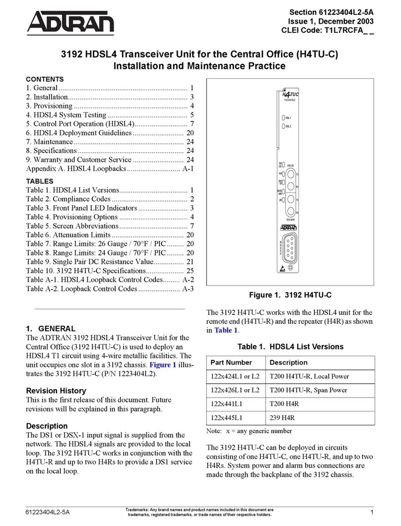
HDSL2
H2TU-C
P/N: 1221002L2
CLEI: SLL5R36G_ _
H TUC
DSL
1221002L2 NB
STAT
RLOS
HLOS
HCRC
ARM
LBK
B8ZS
AHDSL2
*61221002L2-22E*
TROUBLESHOOTING GUIDE
CARD EDGE PINOUT
ADTRAN uses negative ground-referenced span powering voltage (–190 VDC) on the
HDSL2 loop. If desired, disable H2TU-R span powering to allow locally powered H2TU-R
applications.
H2TU-C for Litespan plugs directly into a Litespan channel bank assembly channel unit slot.
Litespan system software must be version 11.0.0 or higher. The tip and ring connections
from the H2TU-C to the shelf are made through card edge pins A3 (Narrowband Tip) and A4
(Narrowband Ring).
H2TU-C for Litespan supports narrowband cabling on the Litespan RT shelf. For more
information regarding the cabling, refer to Alcatel document OSP 363-405-270.
COMPLIANCE
Condition Solution
Power up: all
front panel
indicators off
1. Verify that the channel bank or ONU BPS power LEDs are on.
2. Make sure that unit is fully and correctly inserted into the channel bank or ONU.
3. If step 1 fails, contact Alcatel customer service (800-848-0333). If step 1 passes,
but step 2 fails, replace the H2TU-C.
STAT LED
Red.
1. Verify that the channel bank or ONU BPS power LEDs are on.
2. Verify that the equipment type for the Litespan H2TU-C slot is AHDSL2. Using
TL1, equipment type is shown with the command rtrv-eqpt::AID, where AID is
the access identifier (i.e., cot-1-15).
3. If step 1 fails, contact Alcatel customer service. If step 1 and step 2 pass, replace
the H2TU-C. If step 1 passes but step 2 fails, delete the equipment record (i.e.,
dlt-eqpt::cot-1-15 with TL1) and reinsert the card, or equip the slot with the
currently reserved equipment type.
STAT LED
off; HLOS
LED Red
1. Confirm that the HDSL2 loop is not open.
2. Confirm that the HDSL2 loop is not shorted.
3. Verify the loop conforms to CSA guidelines and is not too long. Loop loss at 196
kHz should be less than 35 dB.
4. Verify that the HDSL2 loop has acceptable noise limits.
5. Verify that tip and ring of each HDSL2 loop belongs to the same twisted pair.
6. If steps 1 through 5 pass, but the HLOS LED remains red, replace the H2TU-C.
7. If step 6 fails, replace the H2TU-R.
STAT LED
off; RLOS
LED Red.
1. Check that framing line coding are set appropriately for T1 data at the H2TU-R.
2. Check that the RLOS LED at the H2TU-R is off.
3. If step 1 fails, change the appropriate framing and line coding. If step 1 passes,
but step 2 fails, a problem may exist at the H2TU-R T1 interface. If the problem
does not exist at the T1 interface, replace the H2TU-C.
Code Input Output
Power Code (PC) F C
Telecommunication Code (TC) – X
Installation Code (IC) A –
FRONT PANEL LEDS
INSTALLATION
After unpacking the unit, inspect it for damage. If damage is noted, file a claim
with the carrier and then contact ADTRAN. Refer to Warranty.
Follow the steps below to install the H2TU-C for Litespan:
1. If present, remove the Access Module Blank from the appropriate access
module slot of the chassis.
2. Pull the ejector latch, located on the lower right-hand side of the H2TU-C
for Litespan front panel, from its closed position.
3. Hold the H2TU-C for Litespan by the front panel while supporting the
bottom edge of the module with the ejector latch opened to engage the
chassis edge. Align the module edges to fit in the lower and upper guide
grooves for the access module slot.
4. Slide the module into the access module slot. Simultaneous thumb pressure
at the top and at the bottom of the module ensures that the module is firmly
positioned against the backplane of the chassis. Secure the module in place
by pushing up and in on the ejector latch.
When installed, the H2TU-C for Litespan runs a series of self-tests. Once the
self-tests are complete, the status LEDs reflect the true state of the hardware.
Label Status Description
DSL z
z
z
2
Green
Yellow
Red
Flashing Red
HDSL2 SNR quality is optimum (6 dB or higher)
HDSL2 SNR quality is marginal (1-5 dB)
HDSL2 SNR quality is poor (0 dB)
HDSL2 Pulse Attenuation is >30 dB
STAT {
z
2
z
Off
Green
Flashing Green
Red
Indicates loss of power to the H2TU-R
Normal; HDSL2 synchronization with H2TU-R
Acquiring HDSL2 synchronization with H2TU-R
Failure indication; unable to start/load firmware
RLOS {
z
Off`
Red
DS1 signal from CPE is present at H2TU-R
DS1 signal from CPE is absent at H2TU-R or
framing does not match
HLOS {
z
2
Off
Red
Flashing Red
HDSL2 synchronization achieved
HDSL2 loss of synchronization
DC continuity fault detected on HDSL2 loop
HCRC {
z
z
Off
Yellow
Red
No HDSL2 CRC errors within last 30 minutes
Four or more HDSL2 CRC errors in last 30 minutes
HDSL2 CRC errors are being detected
ARM/
LBK
{
z
z
Off
Green
Yellow
No loopback active
Loopback is active on this module
Module is armed but loopback is not active
B8ZS {
z
Off
Green
AMI line code
B8ZS line code
61221002L2-22E
0612
HDSL2
H2TU-C for Litespan®Using Narrowband Pairs
PRICING AND AVAILABILITY 800.827.0807
TECH SUPPORT 800.726.8663
RETURN FOR REPAIR 256.963.8722
www.adtran.com
61221002L2-22E
Warranty: ADTRAN will replace or repair this product within the warranty period if it does not meet its published specifications or fails while in service.
Warranty information can be found online at www.adtran.com/warranty.
PROVISIONING OPTIONS / LOOPBACK FUNCTIONS
On initial insertion of the Litespan H2TU-C into the Litespan system, the H2TU-C is provisioned with
the configuration data stored in the shelf controller. Pre-provision the H2TU-C as indicated under “Pre-
Configuration Value” in the table below. The loopback function codes are shown at right.
1. Some settings may not be available at the H2TU-R.
2. This option is only available if the H2TU-R P/N 1221026L1, 1222026L1, 1223026L1 is used in the circuit.
3. This option is not available if the H2TU-R P/N 1221026L1, 1222026L1, 1223026L1 is used in the circuit.
H2TU-C
Options
Corresponding
Litespan
Parameter
H2TU-C
Available
Setting
Corresponding
Litespan Setting
Pre-Configurable
Value
Line Code LINECDE AMI
B8ZS
AMI
B8ZS
B8ZS
Framing 1FMT SF
ESF
Unframed
Auto
SF
ESF
UNFR
AUTO
AUTO
NIU Loopback NIDLPBK Disabled
Enabled
NO
YES
YES
Loopback
Timeout 1
LBKTMO 0
20 Minutes
60 Minutes
120 Minutes
0
20
60
120
120
DS1 TX Level AT 0
–7.5 dB
–15 dB
0.0
–7.5
–15
0.0
New England
Loopback 1,2
LPBKACTR Disabled
Enabled
0000000000000000
0000000000000001
0000000000000000
Latching
Loopback
FT1MODE T1
FT1
NO
YES
NO
Span Power LP Disabled
Enabled
SINK
SOURCE
SOURCE
Customer Loss
Indicator 3
LPBKDEACTCDE AIS
AIS/CI
Loopback
0000000000000000
0000000000000001
0000000000000010
0000000000000001
PRM Setting LPBKACTC None
SPRM
NPRM
Auto (Both)
0000000000000000
0000000000000001
0000000000000010
0000000000000011
0000000000000001
Network Keep
Alive
NTWKKPALV Disabled
Enabled
NO
YES
NO
Note: All codes listed above must be sent for a minimum of 5 seconds in order for them to be detected and acted upon.
1. The H2TU-C and H2TU-R individually detect and act upon in-band loopback control codes. Depending on which list
number of H2TU-R is used with the Litespan H2TU-C, some of these control codes may not cause action (such as loop up,
error injection, etc.) at the H2TU-R. Refer to the H2TU-R documentation for supported control codes.
2. Modules must be armed with 11000b or FF48h for this code to function.
3. In order to behave like a NIU, the H2TU-R can not loop down from the network side with 9393h.
4. This code can be detected only if the modules are armed OR if any loopbacks are active.
5. If NIU is enabled, then the H2TU-R can be in network loopback when the H2TU-C or H2R loop up codes are sent.
Function/Code Response
1 in 3 (1) (100) Loop down everything
1 in 6 (100000) (1) If armed, Loops back at the H2TU-R toward the network.
4 in 7 (1111000) Loops back data from network toward network in the H2TU-C
6 in 7 (1111110) Loops back data from customer toward customer in H2TU-C
1111 1111 0001 1110 Loops back data from network toward network at H2TU-C (FF1E HEX)
0011 1111 0001 1110 Loopback data from customer toward customer at H2TU-C (3F1E HEX)
Arm/ 11000 (known as
2-in-5 pattern) (1)
Loops the H2TU-R toward the network and arms the H2TU-C. No AIS or errors are sent. When
sent from the customer, this code arms all modules.
Arm/ FF48 (1)
(1111 1111 0100 1000)
This pattern is sent on ESF FDL. When sent from network, all modules are armed and the
H2TU-R is looped back toward network. This code has no functionality when sent from the cus-
tomer.
Disarm/ 11100 (1)
(3-in-5 pattern)
All modules are removed from the armed state and looped down when the 11100 pattern is
received. The LBK LEDs turn off on all modules.
Disarm/ FF24 (1)
(1111 1111 0010 0100)
This pattern is sent on ESF facility data link, and disarms and/or loops down all modules.
H2TU-C Network Loop
up / D3D3 (1, 2)
(1101 0011 1101 0011)
If the modules have been armed and no modules are in loopback(5), the H2TU-C loops up toward
the network, 2 seconds of AIS (all 1s) are sent, 5 seconds of data pass, and then 231 bit errors
are injected into the DSX-1 signal. As long as the pattern continues to be sent, 231 errors are
injected every 20 seconds. When the pattern is removed, the module remains in loopback. If the
pattern is reinstated, the injection of 231 bit errors resumes at 20-second intervals.
H2TU-R Address 20 for
extended demarc
/ C754 (1)
(1100 0111 0101 0100)
When sent from the network, an H2TU-R network loopback is activated and a 200-bit error con-
firmation is sent. 2 seconds of AIS (all 1s) is sent, 5 seconds of data pass, and then 200 bit
errors are injected into the DSX-1 signal. As long as the pattern continues to be sent, 200 errors
are injected every 20 seconds. The HDSL2 office unit does not block transmission of far-end NIU
loopback from the customer premise (H2TU-R).
Loop down / 9393 (1, 3)
(1001 0011 1001 0011)
All modules currently in loopback loop down, but remain in the armed state.
Query Loopback
/ D5D5 (1, 2)
(1101 0101 1101 0101)
If the modules are armed and the H2TU-C or H2TU-R are in network loopback, errors are
injected into the DSX-1 signal upon detection of the query loopback pattern. As long as the pat-
tern continues to be sent, errors are injected again every 20 seconds. The number of errors
injected each time depends on which unit is in loopback. 231 errors are injected if the H2TU-C
is in network loopback and 20 at a time if the H2TU-R is in network loopback.
Query Loop
Parameters/ DBDB (2)
(1101 1011 1101 1011)
If the units are armed and the H2TU-C is in network loopback, errors are injected into the DSX-
1 signal upon detection of the query loop parameters pattern. As long as a pattern continues to
be sent, errors are injected again every 20 seconds. The number of errors injected each time
depends on the current status of signal quality and pulse attenuation parameters on each loop.
111 errors are injected if all HDSL2 receiver points (H2TU-C, and H2TU-R) indicate pulse atten-
uation is 30 dB or lower and signal quality (margin) is 6 dB or higher.
11 errors at a time are injected if any of the receiver points indicate pulse attenuation is greater
than 30 dB and/or signal quality (margin) is less than 6 dB.
Loopback Time Out
Override / D5D6 (1, 2, 4)
(1101 0101 1101 0110)
If the units are armed and this pattern is sent, the loopback time out is disabled. The time out
option is updated to NONE on the PROVISIONING menu of the H2TU-R screens (viewable
through the RS-232 port). As long as the units remain armed, the time out remains disabled.
When the units are disarmed, the loopback time out returns to the value it had before the D5D6
code was sent.
Span Power Disable /
6767 (1, 2, 4)
(0110 0111 0110 0111)
If the units are armed and this pattern is sent, the H2TU-C deactivate the span power supply,
removing power to the H2TU-R. As long as the pattern continues to be sent, the span power
supply remains disabled. When the pattern is discontinued, the H2TU-C reactivates its span
power supply, returning power to the remote unit. All units retrain and return to the disarmed
and unlooped state.
HDSL2
H2TU-C for Litespan®Using Narrowband Pairs
Litespan is a Registered trademark of Alcatel, Inc., Paris, France
Other manuals for DDM+ H2TU-C

3

This manual suits for next models

1

Other ADTRAN Transceiver manuals

ADTRAN QSFP28 CWDM4 User manual

ADTRAN

ADTRAN QSFP28 CWDM4 User manual

ADTRAN T200 FNID Instruction Manual

ADTRAN

ADTRAN T200 FNID Instruction Manual

ADTRAN 1442530G1 User manual

ADTRAN

ADTRAN 1442530G1 User manual

ADTRAN QSFP+ User manual

ADTRAN

ADTRAN QSFP+ User manual

ADTRAN jobAid+ PR30 10G PON User manual

ADTRAN

ADTRAN jobAid+ PR30 10G PON User manual

ADTRAN 1442140G2 User manual

ADTRAN

ADTRAN 1442140G2 User manual

ADTRAN HDSL DDM+ HTU-C Instruction Manual

ADTRAN

ADTRAN HDSL DDM+ HTU-C Instruction Manual

ADTRAN T200 H2TU-R User manual

ADTRAN

ADTRAN T200 H2TU-R User manual

ADTRAN 3060 Instruction Manual

ADTRAN

ADTRAN 3060 Instruction Manual

ADTRAN 3192 H4TU-C Instruction Manual

ADTRAN

ADTRAN 3192 H4TU-C Instruction Manual

ADTRAN HTU-C M R Instruction Manual

ADTRAN

ADTRAN HTU-C M R Instruction Manual

ADTRAN T200 H4TU-R Instruction Manual

ADTRAN

ADTRAN T200 H4TU-R Instruction Manual

ADTRAN OC-3 User manual

ADTRAN

ADTRAN OC-3 User manual

ADTRAN 3192 H4TU-C Instruction Manual

ADTRAN

ADTRAN 3192 H4TU-C Instruction Manual

ADTRAN HDSL4 T200 H4TU-R Instruction Manual

ADTRAN

ADTRAN HDSL4 T200 H4TU-R Instruction Manual

ADTRAN T200 H4TU-R User manual

ADTRAN

ADTRAN T200 H4TU-R User manual

ADTRAN 3192 User manual

ADTRAN

ADTRAN 3192 User manual

ADTRAN SFP+ 10 Gig XGS-PON N2 OLT User manual

ADTRAN

ADTRAN SFP+ 10 Gig XGS-PON N2 OLT User manual

ADTRAN 3192 HDSL4 Instruction Manual

ADTRAN

ADTRAN 3192 HDSL4 Instruction Manual

ADTRAN 1700485F1 User manual

ADTRAN

ADTRAN 1700485F1 User manual

ADTRAN 3192 HTU-C Instruction Manual

ADTRAN

ADTRAN 3192 HTU-C Instruction Manual

ADTRAN Combo PON D2 SFP+ User manual

ADTRAN

ADTRAN Combo PON D2 SFP+ User manual

ADTRAN QSFP28 100G SR4 User manual

ADTRAN

ADTRAN QSFP28 100G SR4 User manual

ADTRAN HDSL2 DDM+ H2TU-C User manual

ADTRAN

ADTRAN HDSL2 DDM+ H2TU-C User manual

Popular Transceiver manuals by other brands

Funke ZATR833S Operation and installation instruction

Funke

Funke ZATR833S Operation and installation instruction

TTI TCB-550 Service manual

TTI

TTI TCB-550 Service manual

Yaesu FT-107M Maintenance service manual

Yaesu

Yaesu FT-107M Maintenance service manual

Nokia NHM-4 Series manual

Nokia

Nokia NHM-4 Series manual

CIRCUIT DESIGN STD-302N-R Operation guide

CIRCUIT DESIGN

CIRCUIT DESIGN STD-302N-R Operation guide

Silicon Laboratories Si4432 manual

Silicon Laboratories

Silicon Laboratories Si4432 manual

Yaesu FT DX 3000 operating manual

Yaesu

Yaesu FT DX 3000 operating manual

Yaesu VX-60R operating manual

Yaesu

Yaesu VX-60R operating manual

Midland ALAN 42 MULTI user manual

Midland

Midland ALAN 42 MULTI user manual

Garmin AIS 800 installation instructions

Garmin

Garmin AIS 800 installation instructions

Midland G 7 user manual

Midland

Midland G 7 user manual

Atmel ATAB542x-x-WB Series user guide

Atmel

Atmel ATAB542x-x-WB Series user guide

Kenwood Nexedge NX-5200 user guide

Kenwood

Kenwood Nexedge NX-5200 user guide

Kenwood TR-7730 instruction manual

Kenwood

Kenwood TR-7730 instruction manual

CSI CS108G+ operating manual

CSI

CSI CS108G+ operating manual

Nokia NPM-6 Series Disassembly and Assembly Instructions

Nokia

Nokia NPM-6 Series Disassembly and Assembly Instructions

Nokia RH-41 Series Disassembly

Nokia

Nokia RH-41 Series Disassembly

Kenwood Nexedge NX-210K2 instruction manual

Kenwood

Kenwood Nexedge NX-210K2 instruction manual

manuals.online logo
manuals.online logoBrands
  • About & Mission
  • Contact us
  • Privacy Policy
  • Terms and Conditions

Copyright 2025 Manuals.Online. All Rights Reserved.