61222426L1-5B 1
Section 61222426L1-5B
Issue 2, October 2003
CLEI Code: T1L5JZTCA _ _
T200 HDSL4 Transceiver Unit
for the Remote End
Installation and Maintenance Practice
1. GENERAL
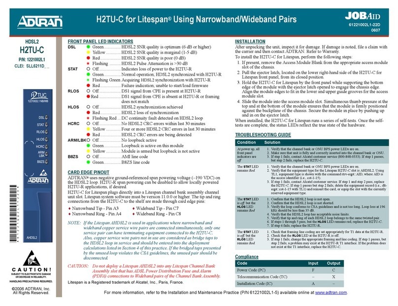
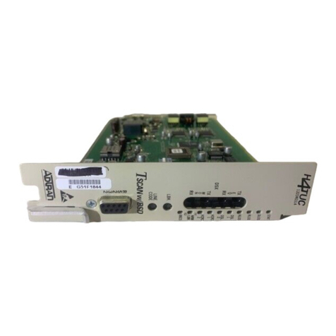
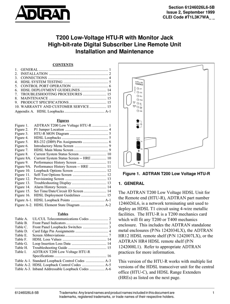
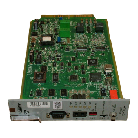
The ADTRAN 4-wire T200 HDSL4 transceiver unit
for the remote end (H4TU-R , P/N 1222426L1, is a
network terminating unit used to deploy an HDSL4 T1
circuit using 4-wire metallic facilities, see Figure 1.
The T200 H4TU-R is a T200 mechanics card which
will fit T200 or T400 mechanic enclosures. The
H4TU-R can be housed in the ADTRAN standalone
metal enclosures (P/N 1242034Lx or 1245034L1 .
Refer to the appropriate ADTRAN practice for more
information. The T200 H4TU-R card can also plug
into the ADTRAN HR12 HDSL4 remote shelf (P/N
1242007Lx , or the ADTRAN HR4 HDSL4 remote
shelf (P/N 1242008L1 .
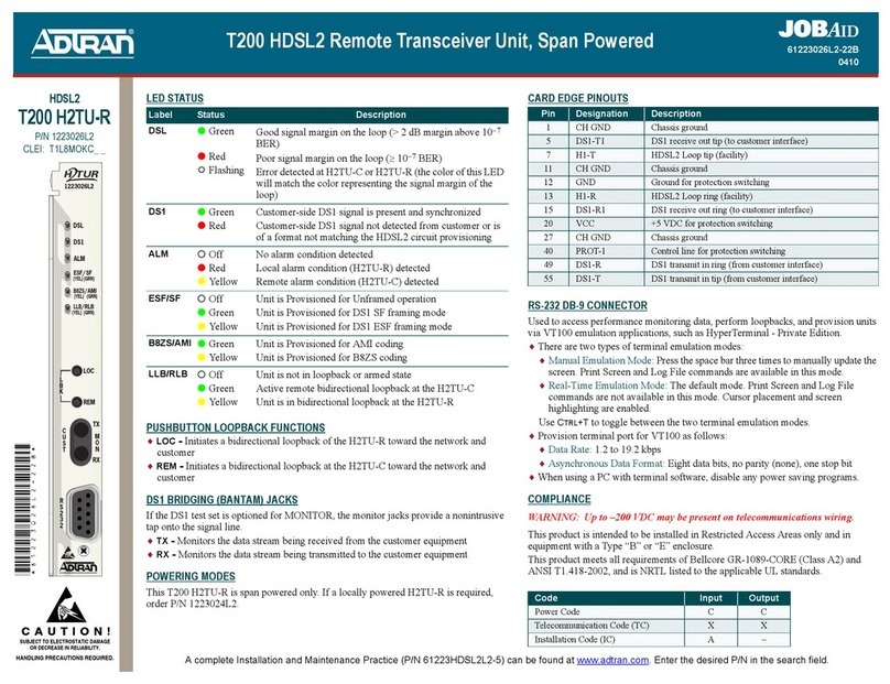
Figure 1. ADTRAN T200 H4TU-R
Trademarks: Any brand names and product names included in this document are
trademarks, registered trademarks, or trade names of their respective holders.
CONTENTS
1. General .................................................................................. 1
2. Installation ............................................................................. 2
3. Connections ........................................................................... 4
4. HDSL4 System Testing ........................................................ 4
5. Front Panel Operation ........................................................... 6
6. Control Port Operation ......................................................... 6
7. HDSL4 Deployment Guidelines ......................................... 17
8. Troubleshooting Procedures ............................................... 22
9. Maintenance ........................................................................ 22
10. Product Specifications ........................................................ 22
11. Warranty and Customer Service ......................................... 22
Appendix A. HDSL4 Loopbacks.............................................. A-1
FIGURES
Figure 1. ADTRAN T200 H4TU-R ......................................... 1
Figure 2. H4TU-R Edge Connector Wiring ............................. 4
Figure 3. H4TU-R MON Diagram .......................................... 4
Figure 4. HDSL4 Loopbacks ................................................... 5
Figure 5. RS-232 (DB-9 Connector Pinout ............................ 6
Figure 6. HDSL4 Main Menu .................................................. 8
Figure 7. Unit Information Screen ........................................... 9
Figure 8. Provisioning Screen .................................................. 9
Figure 9. Span Status Screen ................................................. 10
Figure 10. Detailed Status Screen ............................................ 10
Figure 11. Loopbacks and Test Screen .................................... 11
Figure 12. 15-Minute Performance History Line Data
Screen ..................................................................... 11
Figure 13. 24-Hour Performance History Line Data Screen ... 12
Figure 14. Performance Data Definitions Screen .................... 12
Figure 15. Performance Data Definitions Screen (continued ... 13
Figure 16. Scratch Pad, Circuit ID, Time/Date Screen ............ 13
Figure 17. Terminal Modes Menu ........................................... 14
Figure 18. T1 Alarm History Screen ........................................ 15
Figure 19. HDSL4 Span History Screen .................................. 15
Figure 20. Event History Screen .............................................. 16
Figure 21. System PM/Screen Report Screen .......................... 16
Figure 22. Virtual Terminal Control Screen ............................ 17
Figure 23. HDSL4 Circuit Segments ....................................... 18
Figure 24. Resistance Budget Span Powering Two
Repeaters ................................................................ 20
Figure 25. Resistance Budget Span PoweringTwo
Repeaters (Example .............................................. 21
TABLES
Table 1. Compliance Codes .................................................... 2
Table 2. Front Panel Indicators .............................................. 3
Table 3. Screen Abbreviations ................................................ 7
Table 4. Attenuation Limits from DSL Assistant ................. 18
Table 5. Range Limits: 26 GA Single Segment Only .......... 18
Table 6. Range Limits: 24 GA Single Segment Only .......... 18
Table 7. Single Pair Cable DC Resistance Value ................. 19
Table 8. HDSL4 Insertion Loss Values ................................ 22
Table 9. Single Span and First Segment of Repeatered
Loop ........................................................................ 22
Table 10. Second and Third Segment of Repeatered Loop .... 22
TX
RX
REM
LOC
LBK
1222426L1
DSL 1
DSL 2
DS1
ALM
(GRN)
SF
(YEL)
ESF/
(GRN)
AMI
(YEL)
B8ZS
/
(GRN)
RLB
(YEL)
LLB
/
RX
M
O
N
TX
R
S
2
3
2
Table 11. Troubleshooting Guide ........................................... 23
Table 12. ADTRAN T200 H4TU-R Specifications ............... 24
Table A-1. HDSL4 Loopback Control Codes ........................ A-2
Table A-2. Loopback and Control Codes ....................... A-3, A-4
