ALF-14021-E-01 All-Flo5
SECTION 3
INSTALLATION
The 72100-00 controller requires 100 volts AC (220 volts AC is also available) to power and it delivers 12 volts
DC to the pump. The appropriate 12-volt DC solenoid pump is needed to be used with this controller. This
system is programmed using the keypad on the cover and can be remotely paused or stopped using dry contact
via a Switch terminal on the circuit bord.
This controller should be mounted close to pump is a dry and safe place. The enclosure is NEMA 4X, but All-
Flo advises to avoid hosing the unit. The unit always comes up in a 4-20 mode and is ready to run seconds after
power is applied.
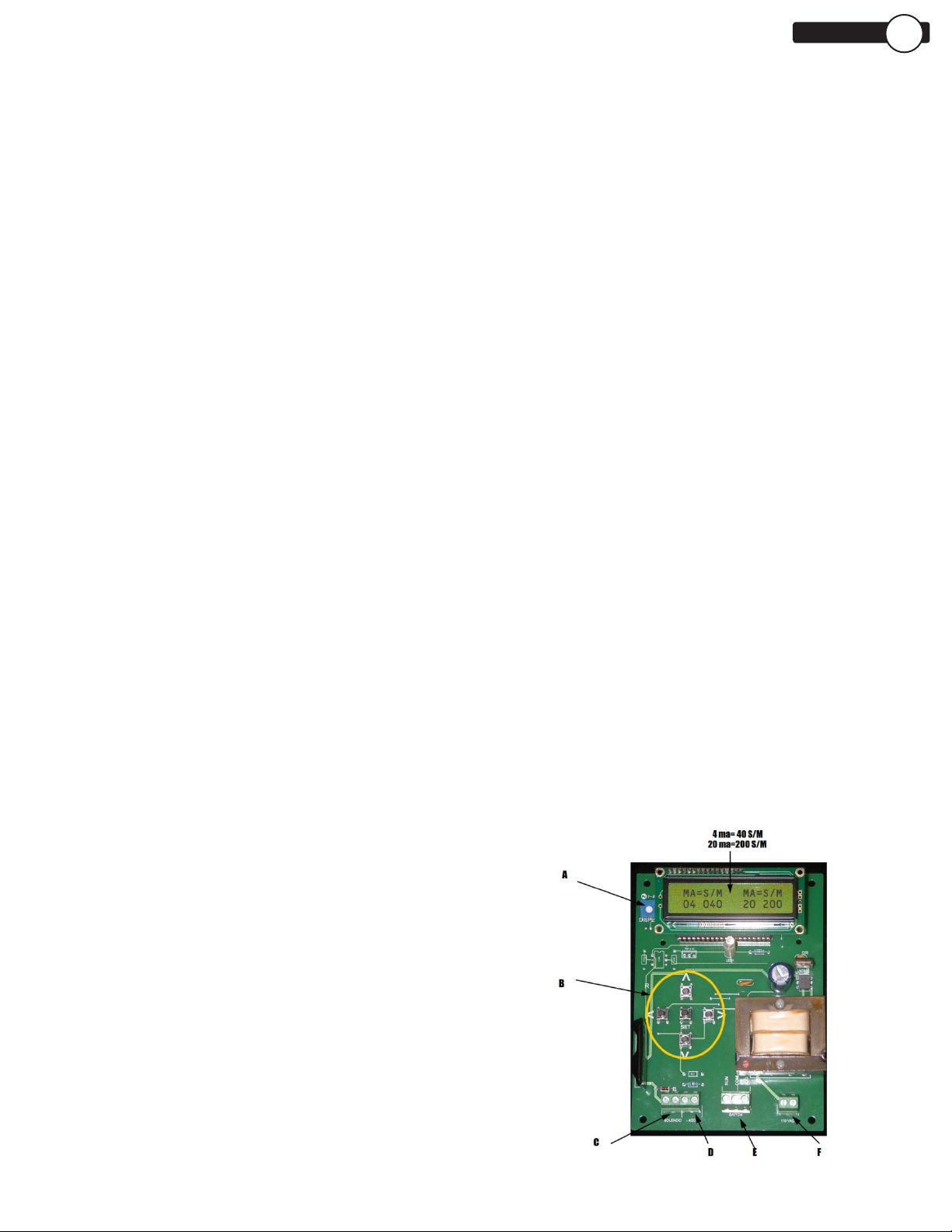
72100-00 BATCH CONTROLLER
A. The Display control changes the contrast on
the LCD display. You will probably never touch
it unless the temperature around the unit is
unusually high or low. If there is no information
on the display, someone probably fiddled with the
control. Just bring it full counterclockwise and
then back off until you have the desired contrast.
B. The Setup Keypad has the Set key in the center
and four keys with arrows around it. They are for
right, left, up and down. The right and left move
the cursor on the display accordingly and the
up and down change the values high- lighted by
the cursor accordingly. They are only used to set
the unit up. Once you have “dialed in” the unit,
you prob- ably won’t be using them and they are
inside the unit, out of harm’s way.
C. The Solenoid output provides 12 volts DC for
the pump’s integral solenoid. You must use the
correct pump solenoid for the pump to operate
properly.
D. The 4-20 ma input gets hooked into the control
loop. You must observe the proper polarity for the
controller to work properly and to protect it from
damage. If you connect the 4-20 input to a current
source of greater magnitude you may damage the
A/D converter in the system so pay attention the
maximum current in the loop.
INTERNALS
E. The Switch terminal connects the control switch
to the system. If the Run terminal (blue wire) and
the Common terminal (black) are connected, the
system reads 4-20 ma. If the Jog (yellow) and
the Common (black) are connect- ed, the system
will run the pump at the average of the high and
low speeds programmed. Never connect all three
wires together; you won’t hurt anything, but you
will confuse the processor and the system won’t
function properly. You can disconnect the unit’s
switch and connect any dry contact set that can
function as a SPDT switch. So, relays, switches
and even PLCs are possible as control devices.
F. The 110 VAC input is the only way to power the
standard unit (220 VAC and 12 VDC versions
are available by specifying) Just make sure the
connections are neat and that for safety reasons
no conductor is exposed. This is the only location
on the circuit board where more than 12 volts is
present.