manuals.online logo
Brands
  1. Home
  2. •
  3. Brands
  4. •
  5. Advantech
  6. •
  7. Computer Hardware
  8. •
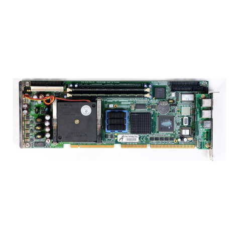
  9. Advantech PCE-7B13-0AA1 Installation and operation manual

Advantech PCE-7B13-0AA1 Installation and operation manual

This manual suits for next models

1

Other Advantech Computer Hardware manuals

Advantech PCIE-1158 Installation and operation manual

Advantech

Advantech PCIE-1158 Installation and operation manual

Advantech PPC RFID 98R3P300010 Installation and operation manual

Advantech

Advantech PPC RFID 98R3P300010 Installation and operation manual

Advantech PCA-6742 Series User manual

Advantech

Advantech PCA-6742 Series User manual

Advantech ACP-7000 User manual

Advantech

Advantech ACP-7000 User manual

Advantech HPC-8000 User manual

Advantech

Advantech HPC-8000 User manual

Advantech SKY-MXM-T1000 User manual

Advantech

Advantech SKY-MXM-T1000 User manual

Advantech PCA-6144S User manual

Advantech

Advantech PCA-6144S User manual

Advantech PPC-IPS User manual

Advantech

Advantech PPC-IPS User manual

Advantech ASMB-610V3 Installation and operation manual

Advantech

Advantech ASMB-610V3 Installation and operation manual

Advantech PCE-5B12-07 Installation and operation manual

Advantech

Advantech PCE-5B12-07 Installation and operation manual

Advantech PPC-3151 User manual

Advantech

Advantech PPC-3151 User manual

Advantech SOM-4463D-S8B2E User manual

Advantech

Advantech SOM-4463D-S8B2E User manual

Advantech MIC-3393 User manual

Advantech

Advantech MIC-3393 User manual

Advantech APAX-5070 User manual

Advantech

Advantech APAX-5070 User manual

Advantech AIMC-3202 Installation and operation manual

Advantech

Advantech AIMC-3202 Installation and operation manual

Advantech MIC-715 User manual

Advantech

Advantech MIC-715 User manual

Advantech SOM-MZ10 Installation and operation manual

Advantech

Advantech SOM-MZ10 Installation and operation manual

Advantech MIO-2375 Installation and operation manual

Advantech

Advantech MIO-2375 Installation and operation manual

Advantech FWA-1211 Installation and operation manual

Advantech

Advantech FWA-1211 Installation and operation manual

Advantech UNO-238 V2 User manual

Advantech

Advantech UNO-238 V2 User manual

Advantech PPC-3211W User manual

Advantech

Advantech PPC-3211W User manual

Advantech ITA-2230 Series Installation and operation manual

Advantech

Advantech ITA-2230 Series Installation and operation manual

Advantech PCA-6184 User manual

Advantech

Advantech PCA-6184 User manual
Advantech SOM-5786 User manual

Advantech

Advantech SOM-5786 User manual

Popular Computer Hardware manuals by other brands

Toshiba TOSVERT VF-MB1/S15 IPE002Z Function manual

Toshiba

Toshiba TOSVERT VF-MB1/S15 IPE002Z Function manual

Shenzhen MEITRACK MVT380 user guide

Shenzhen

Shenzhen MEITRACK MVT380 user guide

TRENDnet TEW-601PC - SUPER G MIMO WRLS PC CARD user guide

TRENDnet

TRENDnet TEW-601PC - SUPER G MIMO WRLS PC CARD user guide

StarTech.com CF2IDE18 instruction manual

StarTech.com

StarTech.com CF2IDE18 instruction manual

Texas Instruments LMH0318 Programmer's guide

Texas Instruments

Texas Instruments LMH0318 Programmer's guide

Gateway 8510946 user guide

Gateway

Gateway 8510946 user guide

Devon IT TC2D Quick setup guide

Devon IT

Devon IT TC2D Quick setup guide

Krüger & Matz Air Shair2 owner's manual

Krüger & Matz

Krüger & Matz Air Shair2 owner's manual

Crystalio VPS-2300 quick guide

Crystalio

Crystalio VPS-2300 quick guide

MYiR FZ3 user manual

MYiR

MYiR FZ3 user manual

Protech Systems BC-K200 Quick reference guide

Protech Systems

Protech Systems BC-K200 Quick reference guide

Miranda DENSITE series DAP-1781 Guide to installation and operation

Miranda

Miranda DENSITE series DAP-1781 Guide to installation and operation

Sierra Wireless Sierra Wireless AirCard 890 quick start guide

Sierra Wireless

Sierra Wireless Sierra Wireless AirCard 890 quick start guide

Leadtek Killer Xeno Pro Quick installation guide

Leadtek

Leadtek Killer Xeno Pro Quick installation guide

Star Cooperation FlexTiny 3 Series Instructions for use

Star Cooperation

Star Cooperation FlexTiny 3 Series Instructions for use

Hotone Ampero user manual

Hotone

Hotone Ampero user manual

Connect Tech Xtreme/104-Express user manual

Connect Tech

Connect Tech Xtreme/104-Express user manual

Yealink WF50 user guide

Yealink

Yealink WF50 user guide

manuals.online logo
manuals.online logoBrands
  • About & Mission
  • Contact us
  • Privacy Policy
  • Terms and Conditions

Copyright 2025 Manuals.Online. All Rights Reserved.

PCE-7B13-0AA1(PCE-5B12-0AA1) Startup Manual 1
Before you begin installing your card, please make sure that
the following materials have been shipped:
• 1 x two ports USB cable
• Startup manual
• M4*6*0.7 round screws (15 pieces)
• 2-year quality warranty card
If any of these items are missing or damaged, please con-
tact your distributor or sales representative immediately.
Standard functions
• PICMG1.3Slot:
PCE-7B13-0A supports PCE-71xx/51xx CPU Cards
PCE-5B12-0A supports PCE-71xx/51xx/50xx CPU Cards
• PCIeSlots:
PCE-7B13-0A: Supports two PCIe x8 slots
PCE-5B12-0A: Supports one PCIe x16 slots
• 32-bitPCI: 10 x 32-bit PCI slots
• USB(2.0)support:4 x universal serial bus ports to
backplane
Mechanical and Environment
• Dimensions:327.66 x 297.67 mm
• Powersupplyvoltage:+12 V, +5V, -12V, -5V, +3.3V,
+5VSBY
• Powerrequirements:Refer to the CPU board , add-on
card & peripherals
• Operatingtemperature:0 ~ 60°C
• Weight:0.6kg (weight of board)
PCE-7B13-0AA1(PCE-5B12-0AA1) PICMG 1.3 Backplane
13(12)-slot BP for 14 slots Chassis, 2(1) PCIe, 10 PCI
Startup Manual
The backplane has a number of connectors and jumpers that
allow you to congure your system to suit your application.
The table below lists the function of each of the connectors and
jumpers.
Connectors
PartReference Function
SHBA1~SHBD1
PICMG1.3 CPU board slot
PPCIE1 PCE-7B13-0A: PCIe x8 slot
PCE-5B12-0A: Not Available
PPCIE2 PCE-7B13-0A: PCIe x8 slot
PCE-5B12-0A: PCIe x16 slot
P1PCI1~P1PCI4 32 Bit, 33/66MHz PCI Bus Slot
(Primary1)
P2PCI1, P2PCI2 32 Bit, 33/66MHz PCI Bus Slot
(Primary2)
PPCI1~PPCI4
32 Bit / 33MHz PCI Bus Slot
(Primary 3)
EATXPWR1 ATX2.0 24-Pin Power connector
EATX12V1 ATX 12V Auxiliary 8-pin power
connector
ATX12V1 ATX 12V 4-pin power connector
PWR3V1 3.3V Auxiliary power connector
PWR3V2 3.3V Auxiliary power connector
VOLT1 Alarm board/CMM Power connector.
FAN1~7 FAN Connector
FANDEC1 Fan speed detector connector
SMBUS1~2 SMBus connector for chassis
monitor
JFP1 Power and Reset Button con-
nector
IPMB1 IPMB Connector
USB12 Two USB port pin header
USB34 Two USB port pin header
Specications
PackingList
For more information on this and other Advantech
products, please visit our website at:
http://www.advantech.com
http://www.advantech.com/eplatform
For technical support and service, please visit our
support website at:
http://www.advantech.com/support
This manual is for the PCE-7B13-0AA1and PCE-
5B12-0AA1 series.
Part No. 20417B1300
Printed in China
1st Edition
Dec. 2022
ConnectorsandJumpers
2 PCE-7B13-0AA1(PCE-5B12-0AA1) Startup Manual
Jumpers
Label Function
PSON1
ATX / AT Mode Selection
JPCICLK1 Primary 1 PCI Bus freq. selection
JPCICLK2 Primary 2 PCI Bus freq. selection
EATXPWER1
Pin Name
1
3.3 V
2 3.3 V
3 GND
4 5 V
5 GND
6
5 V
7 GND
8 Power OK
9
5 V SBY
10
12 V
11 12 V
12 3.3 V
13 3.3 V
14 -12 V
15 GND
16 PSON#
17 GND
18 GND
19 GND
20 -5 V
21 -5 V
22 5 V
23 5 V
24 GND
FAN1~FAN7
Pin Name
1
GND
2 12 V
3 FANIO1~FANIO7
ATX12V1
Pin Name
1
GND
2 GND
3 12 V
4 12 V
EATX12V1
Pin Name
1
GND
2 GND
3 GND
4 GND
5 12 V
6
12 V
7 12 V
8 12 V
PWR3V1&PWR3V2
Pin Name
1
3.3 V
2 3.3 V
3 3.3 V
4 GND
5 GND
6
GND
VOLT1
Pin Name
1
5 V SBY
2 GND
3 GND
4 -5 V
5 5 V
6
3.3 V
7 -12 V
8 12 V
ConnectorsandJumpers(Cont.)ConnectorsandJumpers(Cont.)
PCE-7B13-0AA1(PCE-5B12-0AA1) Startup Manual 3
USB34
Pin Name
1
USBV2
2 USBV2
3 USBD2-
4 USBD3-
5 USBD2+
6
USBD3+
7 GND
8 GND
9
Null
10
GND
PSON1:ATX/ATModeSelection
JumperSetting Function
1-2 closed pins AT mode
2-3 closed pins ATX mode
(default)
JPCICLK1:Primary1PCIBusfreq.Selection
JumperSetting Function
LED
1-2 closed pins 33/66 MHz
Auto Detect On
2-3 closed pins 33 MHz O󰀨
JPCICLK2:Primary2PCIBusfreq.Selection
JumperSetting Function
LED
1-2 closed pins 33/66 MHz
Auto Detect On
2-3 closed pins 33 MHz O󰀨
1 2 3
1 2 3
1 2 3
1 2 3
1 2 3
1 2 3
FANDEC1
Pin Name
1
FANIO1
2 FANIO2
3 FANIO3
4 FANIO4
5 FANIO5
6
FANIO6
7 FANIO7
SMBUS1~SMBUS2
Pin Name
1
5 V
2 C-SMBBUS
3 C-SMBDAT
4 GND
IPMB1
Pin Name
1
IPMB_CLK
2 IPMB_DAT
3 GND
USB12
Pin Name
1
USBV0
2 USBV0
3 USBD0-
4 USBD1-
5 USBD0+
6
USBD1+
7 GND
8 GND
9
Null
10
GND
ConnectorsandJumpers(Cont.) ConnectorsandJumpers(Cont.)
4 PCE-7B13-0AA1(PCE-5B12-0AA1) Startup Manual
Figure 1: Board Layout
BoardLayout
PPCIE1
SMBUS2
PPCIE2
USB12
USB34
FANDEC1
JFP1 SMBUS1
FAN1
FAN2 PSON1 FAN3
PWR3V1
PWR3V2
VOLT1
ATX12V1
EATX12V1
EATXPWR1
FAN4
FAN5
FAN6
JPCICLK2
JPCICLK1
FAN7
IPMB1
P1PCI1
P1PCI2
P1PCI3
P1PCI4
P2PCI1
P2PCI2
PPCI1
PPCI2
PPCI3
PPCI4
PCE-7B13-0AA1(PCE-5B12-0AA1) Startup Manual 5
BoardDimensions
Figure 2: Board Dimensions
51.82 [2.040]
0.00 [0.000]
5.13 [0.202]
25.45 [1.002]
78.74 [3.100]
101.37 [3.991]
124.46 [4.900]
109.29 [4.303]
129.61 [5.103]
149.93 [5.903]
195.91 [7.713]
202.97 [7.991]
190.57 [7.503]
170.25 [6.703]
243.61 [9.591]
260.41 [10.252]
210.89 [8.303]
231.21 [9.103]
251.53 [9.903]
271.85 [10.703]
281.71 [11.091]
292.17 [11.503]
297.44 [11.710]
18.01 [0.709]
0.00 [0.000]
10.16 [0.400]
0.00 [0.000]
22.86 [0.900]
31.12 [1.225]
36.29 [1.429]
9.15 [0.360]
100.84 [3.970]
166.88 [6.570]
258.57 [10.180]
227.33 [8.950]
250.19 [9.850]
304.80 [12.000]
312.42 [12.300]
0.23 [0.009]
5.31 [0.209]
160.65 [6.325]
154.88 [6.098]
160.65 [6.325]
154.94 [6.100]
78.74 [3.100]
101.37 [3.991]
124.23 [4.891]
150.65 [5.931]
243.50 [9.587]
194.84 [7.671]
195.91 [7.713]
178.91 [7.044]
202.97 [7.991]
243.61 [9.591]
260.41 [10.252]
281.71 [11.091]
6 PCE-7B13-0AA1(PCE-5B12-0AA1) Startup Manual
BoardDiagram
Figure 3: Board Diagram
PCE-7B13-0AA1(PCE-5B12-0AA1) Startup Manual 7
PCIRoutingTable
Primary1PCI32-bit,33/66MHz
PCI Interrupt Pin
Route
PCI Pin P1PCI1 P1PCI2 P1PCI3 P1PCI4
INTA BG1_INTA# BG1_INTB# BG1_INTC# BG1_INTD#
INTB BG1_INTB# BG1_INTC# BG1_INTD# BG1_INTA#
INTC BG1_INTC# BG1_INTD# BG1_INTA# BG1_INTB#
INTD BG1_INTD# BG1_INTA# BG1_INTB# BG1_INTC#
IDSEL BG1_AD28 BG1_AD29 BG1_AD30 BG1_AD31
CLK BG1_CLK1 BG1_CLK2 BG1_CLK3 BG1_CLK4
REQ BG1_REQ#0 BG1_REQ#1 BG1_REQ#2 BG1_REQ#3
GNT BG1_GNT#0 BG1_GNT#1 BG1_GNT#2 BG1_GNT#3
Primary2PCI32-bit,33/66MHz
PCI Interrupt Pin
Route
PCI Pin P2PCI1 P2PCI2
INTA BG2_INTA# BG2_INTB#
INTB BG2_INTB# BG2_INTC#
INTC BG2_INTC# BG2_INTD#
INTD BG2_INTD# BG2_INTA#
IDSEL BG2_AD28 BG2_AD29
CLK BG2_CLK1 BG2_CLK2
REQ BG2_REQ#0 BG2_REQ#1
GNT BG2_GNT#0 BG2_GNT#1
Primary3PCI32-bit,33MHz
PCI Interrupt Pin
Route
PCI Pin PPCI1 PPCI2 PPCI3 PPCI4
INTA #PIRQB #PIRQC #PIRQD #PIRQA
INTB #PIRQC #PIRQD #PIRQA #PIRQB
INTC #PIRQD #PIRQA #PIRQB #PIRQC
INTD #PIRQA #PIRQB #PIRQC #PIRQD
IDSEL AD31 AD30 A29 AD28
CLK PPCLKA PPCLKB PPCLKC PPCLKD
REQ PREQ#0 PREQ#1 PREQ#2 PREQ#3
GNT PGNT#0 PGNT#1 PGNT#2 PGNT#3