vii APAX-5580 User Manual
Contents
Chapter 1 Overview...............................................1
1.1 Introduction ............................................................................................... 2
1.2 Safety Precautions .................................................................................... 2
1.3 Accessories............................................................................................... 3
1.4 Product Specifications............................................................................... 3
1.4.1 APAX-5580 System Specifications ............................................... 3
1.4.2 Hardware Specifications ............................................................... 4
Chapter 2 Hardware Functionality.......................5
2.1 Introduction ............................................................................................... 6
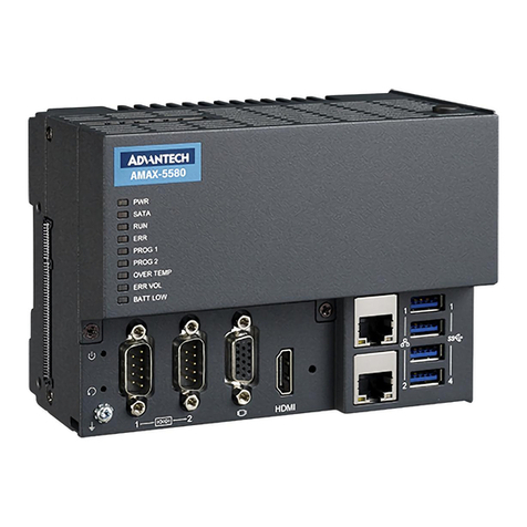
Figure 2.1 Front Panel of APAX-5580 ......................................... 6
Figure 2.2 APAX-5580 Dimensions............................................. 6
2.2 APAX-5580 Interface (COM1)................................................................... 7
2.2.1 RS-232 Interface (COM 1) ............................................................ 7
2.2.2 Automatic Data Flow Control Function for RS-485 ....................... 7
2.3 LAN: Ethernet Connector .......................................................................... 7
2.4 Power Connector ...................................................................................... 7
2.5 USB Connector ......................................................................................... 7
2.6 RTC Battery Specification ......................................................................... 8
Figure 2.3 RTC Battery Location ................................................. 8
2.7 Power Button/Power Management ........................................................... 8
2.8 Reset Button ............................................................................................. 8
2.9 HD Audio................................................................................................... 8
2.10 PCI Express Mini Card Socket.................................................................. 9
2.11 Expansion Module (APAX-5402 Series) ................................................. 10
Chapter 3 Initial Setup ........................................15
3.1 Inserting a mSATA .................................................................................. 16
3.2 Chassis Grounding.................................................................................. 16
Figure 3.1 Chassis Grounding Connection................................ 16
3.3 Connecting Power................................................................................... 16
3.4 Installing a Wireless LAN Card and Antenna .......................................... 17
3.5 BIOS Setup ............................................................................................. 18
3.6 AMT Configuration .................................................................................. 19
3.7 Teaming Configuration............................................................................ 21
Appendix A System Settings and Pin Assignments
25
A.1 Board Connectors and Jumpers ............................................................. 26
Figure A.1 Connector & Jumper Locations (front)...................... 26
Table A.1: Connectors and Jumpers ......................................... 26
Table A.2: COM 1 Mode Setting ................................................ 27
Table A.3: SW2 Selection .......................................................... 27
A.1.1 SW102 Function Switch.............................................................. 28
Table A.4: SW102 Selection...................................................... 28
A.2 RS-232 Standard Serial Port................................................................... 29
Table A.5: RS-232 Serial Port Pin Assignments........................ 29
A.3 RS-422/485 Serial Port ........................................................................... 29
Table A.6: RS-422/485 Serial Port Pin Assignments................. 29


