Advantech ARK-DS520 User manual

User Manual
ARK-DS520
Graphic-Optimized Digital
Signage Player Powered by
NVIDIA GT218

ARK-DS520 User Manual ii
Copyright
The documentation and the software included with this product are copyrighted 2011
by Advantech Co., Ltd. All rights are reserved. Advantech Co., Ltd. reserves the right
to make improvements in the products described in this manual at any time without
notice.
No part of this manual may be reproduced, copied, translated or transmitted in any
form or by any means without the prior written permission of Advantech Co., Ltd.
Information provided in this manual is intended to be accurate and reliable. However,
Advantech Co., Ltd. assumes no responsibility for its use, nor for any infringements
of the rights of third parties, which may result from its use.
Acknowledgements
Award is a trademark of Award Software International, Inc.
IBM, PC/AT, PS/2 and VGA are trademarks of International Business Machines Cor-
poration.
Intel® and ATOM® are trademarks of Intel Corporation.
Microsoft Windows® is a registered trademark of Microsoft Corp.
NVIDIA® and ION are trademarks of NVIDIA Corporation.
RTL is a trademark of Realtek Semi-Conductor Co., Ltd.
ESS is a trademark of ESS Technology, Inc.
UMC is a trademark of United Microelectronics Corporation.
SMI is a trademark of Silicon Motion, Inc.
Creative is a trademark of Creative Technology LTD.
CHRONTEL is a trademark of Chrontel Inc.
All other product names or trademarks are properties of their respective owners.
For more information about this and other Advantech products, please visit our web-
site at:
http://www.advantech.com/
For technical support and service, please visit our support website at:
http://support.advantech.com.tw/support/
Part No. 2006S52000 Edition 1
Printed in China May 2011

iii ARK-DS520 User Manual
Product Warranty (2 Years)
Advantech warrants to you, the original purchaser, that each of its products will be
free from defects in materials and workmanship for two years from the date of pur-
chase.
This warranty does not apply to any products which have been repaired or altered by
persons other than repair personnel authorized by Advantech, or which have been
subject to misuse, abuse, accident or improper installation. Advantech assumes no
liability under the terms of this warranty as a consequence of such events.
Because of Advantech’s high quality-control standards and rigorous testing, most of
our customers never need to use our repair service. If an Advantech product is defec-
tive, it will be repaired or replaced at no charge during the warranty period. For out-
of-warranty repairs, you will be billed according to the cost of replacement materials,
service time and freight. Please consult your dealer for more details.
If you think you have a defective product, follow these steps:
1. Collect all the information about the problem encountered. (For example, CPU
speed, Advantech products used, other hardware and software used, etc.) Note
anything abnormal and list any onscreen messages you get when the problem
occurs.
2. Call your dealer and describe the problem. Please have your manual, product,
and any helpful information readily available.
3. If your product is diagnosed as defective, obtain an RMA (return merchandise
authorization) number from your dealer. This allows us to process your return
more quickly.
4. Carefully pack the defective product, a fully-completed Repair and Replacement
Order Card and a photocopy of the proof of purchase date (such as your sales
receipt) in a shippable container. A product returned without proof of the pur-
chase date is not eligible for warranty service.
5. Write the RMA number visibly on the outside of the package and ship it prepaid
to your dealer.
Declaration of Conformity
FCC Class A
Note: This equipment has been tested and found to comply with the limits for a Class
A digital device, pursuant to part 15 of the FCC Rules. These limits are designed to
provide reasonable protection against harmful interference when the equipment is
operated in a commercial environment. This equipment generates, uses, and can
radiate radio frequency energy and, if not installed and used in accordance with the
instruction manual, may cause harmful interference to radio communications. Opera-
tion of this equipment in a residential area is likely to cause harmful interference in
which case the user will be required to correct the interference at his own expense.

ARK-DS520 User Manual iv
Technical Support and Assistance
1. Visit the Advantech website at www.advantech.com/support where you can find
the latest information about the product.
2. Contact your distributor, sales representative, or Advantech's customer service
center for technical support if you need additional assistance. Please have the
following information ready before you call:
–Product name and serial number
–Description of your peripheral attachments
–Description of your software (operating system, version, application software,
etc.)
–A complete description of the problem
–The exact wording of any error messages
Warnings, Cautions and Notes
Warning! Warnings indicate conditions, which if not observed, can cause personal
injury!
Caution! Cautions are included to help you avoid damaging hardware or losing
data. e.g.
There is a danger of a new battery exploding if it is incorrectly installed.
Do not attempt to recharge, force open, or heat the battery. Replace the
battery only with the same or equivalent type recommended by the man-
ufacturer. Discard used batteries according to the manufacturer's
instructions.
Note! Notes provide optional additional information.

v ARK-DS520 User Manual
Safety Instructions
1. Read these safety instructions carefully.
2. Keep this User Manual for later reference.
3. Disconnect this equipment from any AC outlet before cleaning. Use a damp
cloth. Do not use liquid or spray detergents for cleaning.
4. For plug-in equipment, the power outlet socket must be located near the equip-
ment and must be easily accessible.
5. Keep this equipment away from humidity.
6. Put this equipment on a reliable surface during installation. Dropping it or letting
it fall may cause damage.
7. The openings on the enclosure are for air convection. Protect the equipment
from overheating. DO NOT COVER THE OPENINGS.
8. Make sure the voltage of the power source is correct before connecting the
equipment to the power outlet.
9. Position the power cord so that people cannot step on it. Do not place anything
over the power cord.
10. All cautions and warnings on the equipment should be noted.
11. If the equipment is not used for a long time, disconnect it from the power source
to avoid damage by transient overvoltage.
12. Never pour any liquid into an opening. This may cause fire or electrical shock.
13. Never open the equipment. For safety reasons, the equipment should be
opened only by qualified service personnel.
14. If one of the following situations arises, get the equipment checked by service
personnel:
The power cord or plug is damaged.
Liquid has penetrated the equipment.
The equipment has been exposed to moisture.
The equipment does not work well, or you cannot get it to work according to
the user's manual.
The equipment has been dropped and damaged.
The equipment has obvious signs of breakage.
15. DO NOT LEAVE THIS EQUIPMENT IN AN ENVIRONMENT WHERE THE
STORAGE TEMPERATURE MAY GO BELOW -20° C (-4° F) OR ABOVE 60° C
(140° F). THIS COULD DAMAGE THE EQUIPMENT. THE EQUIPMENT
SHOULD BE IN A CONTROLLED ENVIRONMENT.
16. CAUTION: DANGER OF EXPLOSION IF BATTERY IS INCORRECTLY
REPLACED. REPLACE ONLY WITH THE SAME OR EQUIVALENT TYPE
RECOMMENDED BY THE MANUFACTURER, DISCARD USED BATTERIES
ACCORDING TO THE MANUFACTURER'S INSTRUCTIONS.
The sound pressure level at the operator's position according to IEC 704-1:1982 is
no more than 70 dB (A).
RESTRICTED ACCESS AREA: The equipment should only be installed in a
Restricted Access Area.
DISCLAIMER: This set of instructions is given according to IEC 704-1. Advantech
disclaims all responsibility for the accuracy of any statements contained herein.

ARK-DS520 User Manual vi
Packing List
Before installation, please ensure the following items have been shipped:
1 x ARK-DS520 Unit
1 x Power Adaptor
1 x Driver/Utility CD/manual
1 x China RoHS
1 x Simplified Chinese User Manual for CCC
Power Cord & Accessory Options
Part Number Description
Part Number Description
1702002600 3-pin power cord (US)
1700018705 3-pin power cord (EU)
1702031801 3-pin power cord (UK)
1702031836 3-pin power cord (AU)
1700000237 3-pin power cord (JP)
Part Number Description
AMO-WIFI01E WIFI 802.11 b/g/n mini PCIe module (w/antenna)
AMO-HSDPA01E HSDPA mini PCIe module (w/antenna)
Note! A wireless LED will be activated when inserting WLAN card into either
one of the mini PCIe card slots in ARK-DS520.

vii ARK-DS520 User Manual
Contents
Chapter 1 General Introduction ...........................1
1.1 Introduction ............................................................................................... 2
1.2 Product Features....................................................................................... 2
1.2.1 General ......................................................................................... 2
1.2.2 Display .......................................................................................... 2
1.2.3 Power Consumption...................................................................... 2
1.3 Hardware Specifications ........................................................................... 2
1.4 Mechanical Specifications......................................................................... 3
1.4.1 Dimensions ................................................................................... 3
Figure 1.1 ARK-DS520 Mechanical Dimensions ......................... 3
1.4.2 Weight........................................................................................... 4
1.5 Power Requirements................................................................................. 4
1.5.1 System Power............................................................................... 4
1.5.2 RTC Battery .................................................................................. 4
1.6 Environmental Specifications .................................................................... 4
1.6.1 Operating Temperature................................................................. 4
1.6.2 Relative Humidity .......................................................................... 4
1.6.3 Storage Temperature.................................................................... 4
1.6.4 Vibration Loading During Operation.............................................. 4
1.6.5 Shock During Operation................................................................ 4
1.6.6 Safety............................................................................................ 4
1.6.7 EMC .............................................................................................. 4
Chapter 2 Hardware Installation ..........................5
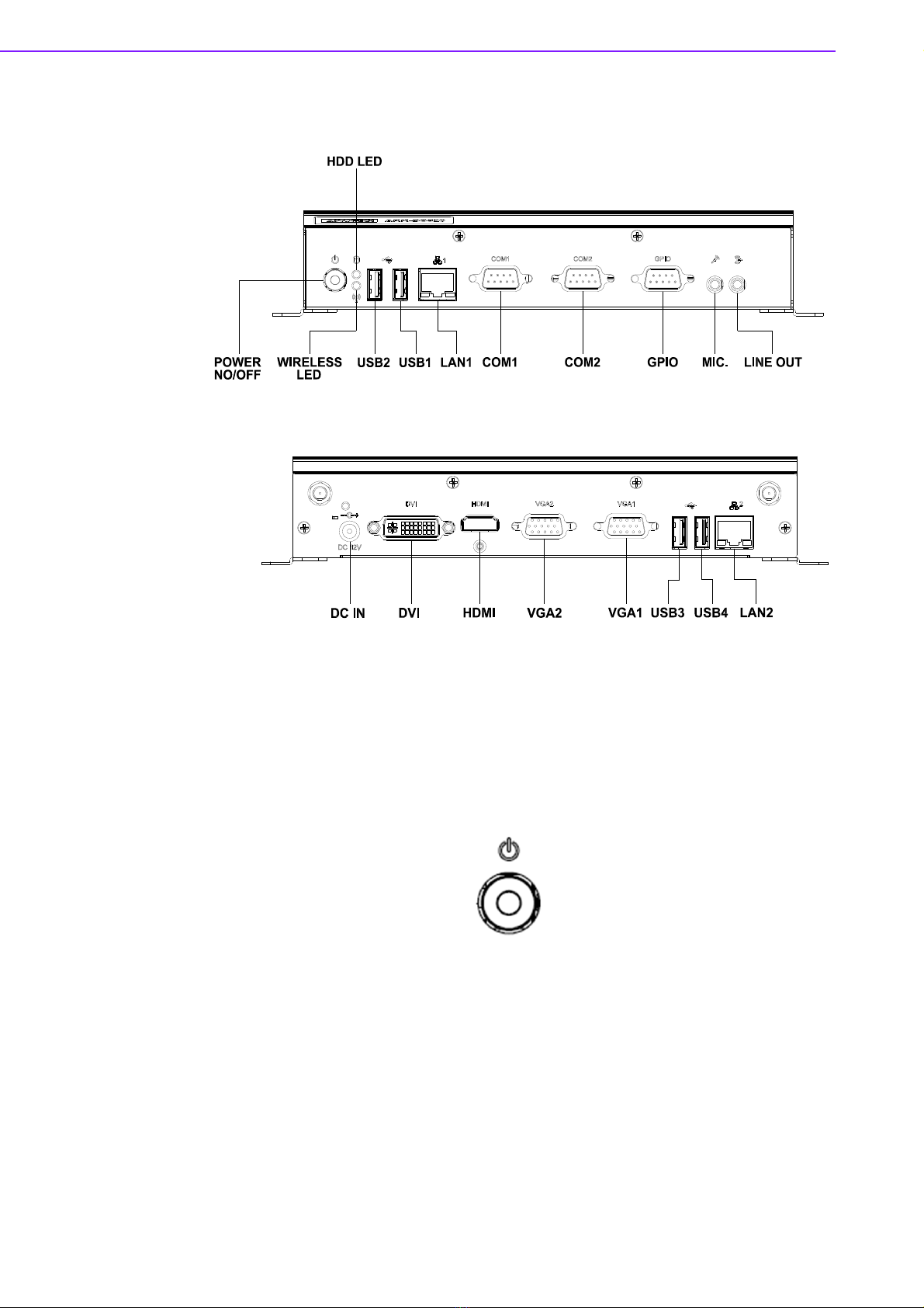
2.1 ARK-DS520 I/O Connectors ..................................................................... 6
Figure 2.1 ARK-DS520 Front View.............................................. 6
Figure 2.2 ARK-DS520 Rear View .............................................. 6
2.2 ARK-DS520 Front Side External I/O Connectors...................................... 6
2.2.1 Power ON/OFF Button.................................................................. 6
Figure 2.3 Power ON/OFF Button ............................................... 6
2.2.2 USB 1~4 Connectors .................................................................... 7
Figure 2.4 USB 1~4 Connectors.................................................. 7
Table 2.1: USB 1~4 Port Pin Assignments.................................. 7
2.2.3 COM 1,2 Connector ...................................................................... 7
Figure 2.5 COM 1,2 Connector.................................................... 7
Table 2.2: COM 1,2 Connector Pin Assignments........................ 7
2.2.4 Audio Connector ........................................................................... 8
Figure 2.6 Line-out and MIC Connector ...................................... 8
2.2.5 Ethernet Connector (LAN) ............................................................ 8
Figure 2.7 Ethernet Connector .................................................... 8
Table 2.3: LAN Connector Pin Assignments ............................... 8
2.3 ARK-DS520 Rear Side External I/O Connectors ...................................... 9
2.3.1 Power Input Connector ................................................................. 9
Figure 2.8 Power Input Connector............................................... 9
2.3.2 DVI-D Connector........................................................................... 9
Figure 2.9 DVI-D Connector ........................................................ 9
Table 2.4: DVI-D Connector Pin Assignments ............................ 9
2.3.3 HDMI Connector ......................................................................... 10
Figure 2.10HDMI Connector....................................................... 10
Table 2.5: HDMI Connector Pin Assignments ........................... 10
2.3.4 VGA 1,2 Connector..................................................................... 11
Figure 2.11VGA 1, 2 Connector ................................................. 11
Table 2.6: VGA 1,2 Connector Pin Assignments....................... 11

ARK-DS520 User Manual viii
2.4 Hardware Installation .............................................................................. 12
2.4.1 Memory Installation..................................................................... 12
Figure 2.12Memory Installation .................................................. 12
2.4.2 HDD Installation.......................................................................... 12
Figure 2.13HDD Installation ....................................................... 12
2.4.3 CF Card Installation .................................................................... 13
Figure 2.14CF Card Installation.................................................. 13
2.4.4 Mini Card & SIM Card Installation............................................... 13
Figure 2.15SIM Card Installation ................................................ 13
2.4.5 LAN Card Wireless Antenna Installation..................................... 14
Figure 2.16LAN Card Wireless Antenna Installation .................. 14
Chapter 3 BIOS Settings .................................... 15
3.1 BIOS Introduction.................................................................................... 16
3.2 Entering BIOS Setup............................................................................... 16
Figure 3.1 Setup Program Initial Screen ................................... 16
3.2.1 Main Setup.................................................................................. 17
Figure 3.2 Main Setup Screen................................................... 17
3.2.2 Advanced BIOS Features Setup................................................. 18
Figure 3.3 Advanced BIOS Features Setup Screen.................. 18
Figure 3.4 CPU Configuration Setting ....................................... 18
Figure 3.5 IDE Configuration ..................................................... 19
Figure 3.6 AHCI Configuration .................................................. 20
Figure 3.7 Super I/O Chipset Configuration .............................. 21
Figure 3.8 Hardware Health Configuration ................................ 21
Figure 3.9 ACPI Settings ........................................................... 22
Figure 3.10General ACPI Configuration..................................... 22
Figure 3.11Advanced ACPI Configuration.................................. 23
Figure 3.12Chipset ACPI Configuration ..................................... 23
Figure 3.13APM Configuration ................................................... 24
Figure 3.14USB Configuration.................................................... 25
3.2.3 PCI/PnP Configurations.............................................................. 26
Figure 3.15PCI/PnP Setup (Top)................................................ 26
3.2.4 Boot Settings .............................................................................. 27
Figure 3.16Boot Setup Utility...................................................... 27
Figure 3.17Boot Settings Configuration...................................... 27
Figure 3.18BIOS Setup Boot Device Priority.............................. 28
Figure 3.19BIOS Setup Hard Disk Drives .................................. 29
3.2.5 Security Setup ............................................................................ 29
Figure 3.20Password Configuration ........................................... 29
3.2.6 Advanced Chipset Configurations .............................................. 30
Figure 3.21Advanced Chipset Settings ...................................... 30
Figure 3.22North Bridge Chipset Configuration.......................... 30
Figure 3.23South Bridge Chipset Configuration ......................... 31
3.2.7 Exit Option .................................................................................. 32
Figure 3.24Exit Options .............................................................. 32
Chapter 4 Software Installation......................... 35
4.1 Driver Installation .................................................................................... 36
4.1.1 Chipset Driver Installation........................................................... 36
4.1.2 Graphic Driver Installation .......................................................... 40
4.1.3 LAN Driver Installation ................................................................ 42
4.1.4 LAN Driver Installation (RTL)...................................................... 45
4.1.5 Audio Driver Installation.............................................................. 47

Chapter 1
1General Introduction
This chapter gives background
information on ARK-DS520 series.

ARK-DS520 User Manual 2
1.1 Introduction
ARK-DS520 is powered by an Intel® Atom™ D525 dual-core processor with an inte-
grated nVidia GT218 (ION2) graphic module for Full HD playback. There is also a
another fanless option based on the Intel® Atom™ N455 single-core processor. With
NVIDIA Optimus technology, the system energizes media playback with over 10
times normal performance, due to its combination of integrated graphics, high perfor-
mance editing and converting of videos, and rich 3D user interface. ARK-DS520
delivers advanced graphics performance with lower cost to meet your signage appli-
cation requirements.
ARK-DS520 has a rich combination of video output interfaces (e.g.: 2 x VGA, VGA +
HDMI, HDMI + DVI) to provide dual display output simultaneously. For better connec-
tivity, it has internal support for 2 x Mini PCIe interfaces for add-on functions such as
wireless network and TV tuner cards to fulfill different requirements. And ARK-DS520
also supports 4 x USB ports, 2 x COM (RS-232) ports and DIO ports for system inte-
gration and applications.
1.2 Product Features
1.2.1 General
Intel® Atom™ D525 1.8 GHz, Intel® Atom™ N455 1.66 GHz
Rich video I/O combination supports dual display (e.g.: 2 x VGA, VGA + HDMI,
HDMI + DVI)
Supports 2 x GbE, 4 x USB 2.0, 2 x COM and 8-bit GPIO ports
Internal 2.5-inch SATA HDD drive bay
Built-in MiniPCIe slot for easy expansion e.g. WiFi, TV-tuner, etc.
Easy integration and easy maintenance
1.2.2 Display
Dual-display support; up to 1080p full HD video playback performance (subject
to the video media format and playback software)
1.2.3 Power Consumption
Typical: 18 W (CPU is Intel Atom D525 1.8 GHz and w/o expansion)
Max.: 30 W (CPU is Intel Atom D525 1.8 GHz and w/o expansion)
1.3 Hardware Specifications
CPU: Intel Atom D525 1.8 GHz (or Intel Atom N455 1.66 GHz)
System Chipset: Intel Atom D525/N455 + ICH8M
BIOS: AMI 16 Mbit Flash BIOS
System Memory: 2 x DDR3 SODIMM sockets, supports DDR3 800 MHz up to
4 GB (D525) & supports DDR3 667 MHz up to 2 GB (N455)
Graphic chipset: nVidia GT218-ILV-B1Video Memory Size: independent dis-
play memory 512 MB
SSD: Supports 1 x CF Card TYPE I/II
HDD: Supports 1 x 2.5" SATA HDD
Watchdog Timer: Single chip watchdog 255-level interval timer, setup by soft-
ware
I/O Interface: 2 x RS-232 ports

3 ARK-DS520 User Manual
Chapter 1 General Introduction
USB: 4 x USB 2.0 compliant ports
Audio: Supports line-out, microphone-in
Ethernet Chipset: 1 x Intel WG82567V + 1 x Realtek RTL8111D-GR (Gigabit
LAN)
–Speed: 10/100/1000 Mbps
–Interface: 2 x RJ-45 jacks with LED
–Standard: IEEE 802.3z/ab (1000 Base-T) or IEEE 802.3u 100 Base-T
compliant
Expansion
miniPCIe: 2 sockets
Resolution
–VGA: up to 2048 x 1536 at 60 Hz;
–DVI-D: single link 1600 x 1200 at 60 Hz;
–HDMI: Up to 1920 x 1080 at 60 Hz (1080P)
Dual Independent Outputs:
–VGA1+VGA2
–VGA1+HDMI
–VGA1+DVI-D
–VGA2+HDMI
–VGA2+DVI-D
–HDMI+DVI-D
1.4 Mechanical Specifications
1.4.1 Dimensions
220 x 44.2 x 150 mm (8.67" x 1.74" x 5.91"), without mounting brackets.
Figure 1.1 ARK-DS520 Mechanical Dimensions

ARK-DS520 User Manual 4
1.4.2 Weight
1.7 kg (3.74 lb.)
1.5 Power Requirements
1.5.1 System Power
Minimum power input: DC 12 V, 5 A
1.5.2 RTC Battery
3 V/200 mAH BR2032
1.6 Environmental Specifications
1.6.1 Operating Temperature
0° C - 40° C (32~104° F)
1.6.2 Relative Humidity
95% @ 40° C (non-condensing)
1.6.3 Storage Temperature
-20~70° C (-4~167° F)
1.6.4 Vibration Loading During Operation
0.3 Grms, IEC 60068-2-64, random, 5 ~ 500 Hz, 1 Oct./min, 1 hr./axis.
1.6.5 Shock During Operation
20 G, IEC 60068-2-27, half sine, 11 ms duration
1.6.6 Safety
BSMI, CCC
1.6.7 EMC
CE, FCC

Chapter 2
2Hardware Installation
This chapter introduces external
I/O and the installation of ARK-
DS520 Hardware.
ARK-DS520 User Manual 6
2.1 ARK-DS520 I/O Connectors
Figure 2.1 ARK-DS520 Front View
Figure 2.2 ARK-DS520 Rear View
2.2 ARK-DS520 Front Side External I/O Connectors
2.2.1 Power ON/OFF Button
ARK-DS520 has a power ON/OFF button on the front side. Push this button to turn
the system ON and OFF. It also supports a 4 second delay soft power off.
Figure 2.3 Power ON/OFF Button

7 ARK-DS520 User Manual
Chapter 2 Hardware Installation
2.2.2 USB 1~4 Connectors
The ARK-DS520 provides four USB interface connectors (2 x USB ports on the front-
side; and 2 x USB ports on the rear-side), which gives complete Plug & Play and hot
swapping capability for up to 127 external devices. The USB interface is compliant
with USB UHCI, Rev. 2.0. The USB interface supports Plug and Play, which enables
you to connect or disconnect a device without turning off the computer.
Figure 2.4 USB 1~4 Connectors
2.2.3 COM 1,2 Connector
ARK-DS520 provides two D-sub 9-pin connectors serial communication interface
ports. The ports support RS-232 mode communications.
Figure 2.5 COM 1,2 Connector
Table 2.1: USB 1~4 Port Pin Assignments
Pin Signal Name
1VCC
2 USB Data-
3 USB Data+
4GND
Table 2.2: COM 1,2 Connector Pin Assignments
Pin Signal Name
1 DCD
2RxD
3TxD
4DTR
5GND
6DSR
7RTS
8CTS
9RI

ARK-DS520 User Manual 8
2.2.4 Audio Connector
Line Out: Stereo speakers, earphone or front surround speakers can be connected
to the line out jack.
MIC In: Microphone must be connected to MIC In jack.
Figure 2.6 Line-out and MIC Connector
2.2.5 Ethernet Connector (LAN)
ARK-DS520 provides two RJ-45 LAN interface connectors (1 x LAN connector on the
front-side; 1 x LAN connector on the rear-side); they are fully compliant with IEEE
802.3u 10/100/1000 Base-T CSMA/CD standards. The Ethernet port provides a stan-
dard RJ-45 jack connector with LED indicators on the front side to show its Active/
Link status and speed status.
Figure 2.7 Ethernet Connector
Table 2.3: LAN Connector Pin Assignments
Pin Signal Name
1MDI0+
2MDI0-
3MDI1+
4MDI1-
5GND
6GND
7MDI2+
8MDI2-
9MDI3+
10 MDI3-
11 VCC
12 ACT
13 +V3.3 & Link1000#
14 +V3.3 & Link100#

9 ARK-DS520 User Manual
Chapter 2 Hardware Installation
2.3 ARK-DS520 Rear Side External I/O Connectors
2.3.1 Power Input Connector
ARK-DS520 comes with a DC-Jack header that takes 12 VDC external power input.
Figure 2.8 Power Input Connector
2.3.2 DVI-D Connector
Figure 2.9 DVI-D Connector
Table 2.4: DVI-D Connector Pin Assignments
Pin Signal Name
1TMDSData2-
2TMDSData2+
3GND
4NC
5NC
6SCL
7SDA
8NC
9TMDSData1-
10 TMDS Data1+
11 GND
12 NC
13 NC
14 +5 V Power
15 GND
16 Hot Plug Detect
17 TMDS Data0-
18 TMDS Data0+
19 GND
20 NC
21 NC
22 GND
23 TMDS Clock+
24 TMDS Clock-
C5 NC

ARK-DS520 User Manual 10
2.3.3 HDMI Connector
The HDMI (High-Definition Multimedia Interface) provides an all-digital audio/video
interface to transmit the uncompressed audio/video signals and is HDCP compliant.
Connect the HDMI audio/video device to this port. HDMI technology can support a
maximum resolution of 1920 x 1080p but the actual resolutions supported depend on
the monitor being used.
Figure 2.10 HDMI Connector
Table 2.5: HDMI Connector Pin Assignments
Pin Signal Name
1TMDSData2+
2GND
3TMDSData2-
4TMDSData1+
5GND
6TMDSData1-
7TMDSData0+
8GND
9TMDSData0-
10 TMDS Clock+
11 GND
12 TMDS Clock-
13 NC
14 NC
15 SCL
16 SDA
17 GND
18 +5 V Power
19 Hot Plug Detect

11 ARK-DS520 User Manual
Chapter 2 Hardware Installation
2.3.4 VGA 1,2 Connector
The ARK-DS520 provides two high resolution VGA interfaces connected by a D-sub
15-pin connector to support VGA CRT compatible monitors. It supports display reso-
lutions of up to 2048 x 1536 @ 60 Hz.
Figure 2.11 VGA 1, 2 Connector
Table 2.6: VGA 1,2 Connector Pin Assignments
Pin Signal Name
1RED
2GREEN
3BLUE
4NC
5GND
6GND
7GND
8GND
9NC
10 GND
11 NC
12 DDC DAT
13 H-SYNC
14 V-SYNC
15 DDC CLK

ARK-DS520 User Manual 12
2.4 Hardware Installation
2.4.1 Memory Installation
1. Remove Mini-PCIe cover, HDD cover by loosening the 5 fixing screws.
2. Remove the heatsink by loosening the 4 fixing screws on front and rear panels,
and 2 fixing screws inside the chassis.
3. Insert the memory into memory socket.
4. Reverse the above-mentioned steps to assemble the system.
Figure 2.12 Memory Installation
2.4.2 HDD Installation
1. Assemble the 2.5-inch SATA HDD on HDD bracket with 4 HDD screws.
2. Install the HDD module into the system.
3. Assemble back the HDD cover with the screws.
Figure 2.13 HDD Installation
Table of contents
Other Advantech Media Player manuals

Advantech
Advantech DSA-2101 Series User manual

Advantech
Advantech DS-270 User manual

Advantech
Advantech DS-082 Series User manual

Advantech
Advantech DSA-2130E Series User manual

Advantech
Advantech DSA-3020 User manual

Advantech
Advantech DSA-2130 User manual

Advantech
Advantech DSA-2130SAE User manual

Advantech
Advantech USM-110 Delight User manual

Advantech
Advantech USM-110 Delight Installation and operation manual

Advantech
Advantech DS-081 Series User manual


