ARB Airlocker RD214 User manual
RD214
NISSAN H260, 34 SPLINE
AIR OPERATED
LOCKING DIFFERENTIAL
INSTALLATION GUIDE

No liability is assumed for damages resulting in the use of the information contained herein.
ARB AIR LOCKER Locking Differentials and AIR LOCKER are trademarks of ARB Corporation Limited.
Other product names used herein are for identification purposes only and may be trademarks of their respective owners.
ARB 4x4 ACCESSORIES
Corporate Head Office
42-44 Garden St Tel: +61 (3) 9761 6622
Kilsyth, Victoria Fax: +61 (3) 9761 6807
AUSTRALIA
3137
www.arb.com.au
Table of Contents:
1
1 Introduction
3
1.1
Pre-Installation Preparation
3
1.2
Tool-Kit Recommendations
4
2 Removing the Existing Differential
5
2.1
Vehicle Support
5
2.2
Differential Fluid Drain
5
2.3
Removing the Axles
5
2.4
Marking the Bearing Caps
6
2.5
Checking the Current Backlash Amount
7
2.6
Removing the Differential Carrier
8
3 Installing the Air Locker
9
3.1
Mounting the Ring Gear
9
3.2
Installing the Carrier Bearings
11
3.3
Drilling and Tapping the Bulkhead Port
11
3.4
Assembling the Seal Housing
13
3.5
Modifying the Bearing Cap
14
3.6
Final Air Locker Assembly
16
3.7
Setting up the Bulkhead Fitting
17
3.8
Profiling the Seal Housing Tube
19
3.9
Bench Testing the Air Locker
20
3.10
Reinstalling the Differential & Axles
21
4 Installing the Air System
22
4.1
Mounting the Solenoid
22
4.2
Running & Securing the Air Line
24
4.3
Connection to the Bulkhead Fitting
25
5 Mounting & Connecting the Electrical System
27
5.1
Mounting the Actuator Switch(es)
27
5.2
Wiring the Actuator System
28
6 Testing & Final Assembly
31
6.1
Leak Testing
31
6.2
Testing the Air Locker Actuation
31
6.3
Filling the Differential
32
6.4
Post-Installation Check List
33
7 Parts List
35
7.1
Exploded Assembly Diagram
35
7.2
Specifications
35
7.3
Itemized Parts List
36

2

1 Introduction
3
IMPORTANT :
BEFORE ATTEMPTING TO DISMANTLE YOUR VEHICLE FOR THIS
INSTALLATION, PLEASE READ THIS INSTALLATION GUIDE IN ITS
ENTIRETY, AS WELL AS ALL APPLICABLE SECTIONS OF YOUR
VEHICLE MANUFACTURER’S SERVICE MANUAL.
1.1 Pre-Installation Preparation
This booklet is to be used in conjunction with your vehicle
manufacturer’s service manual. ARB endeavors to account for every
possible variation in vehicle model when publishing its installation
guides, and guides are updated regularly as new model information
becomes available, however, the rapid and globally varied release of
some vehicles makes it difficult to insure that your vehicle model has
been accurately accounted for. In the case of any technical
discrepancies between this guide and your service manual, we
strongly advise that you adhere to the specifications and techniques
as documented in your service manual.
Although your ARB Air Locker comes complete with all the step by
step instructions you will need to supplement your vehicle
manufacturer’s service manual and install your new differential, ARB
recommends that you have your Air Locker installed by a trained
professional. Many ARB distributors around the world have been fully
instructed in Air Locker installations by ARB, and have gained a wealth
of experience and skill from years of performing similar installations.
Once you begin this installation your vehicle will be immobile until all
steps of the installation are complete. Make sure your Air Locker kit is
the correct model for your vehicle and that it contains all of the parts
listed on back cover of this booklet. Also be sure you have
appropriately equipped yourself with all the necessary tools, parts, and
materials to complete this installation (see Section 1.2 Tool-Kit
Recommendations), and that you have allowed for an appropriate
amount of vehicle down time.
HINT : Place a mark inside each of the symbols as
you complete each step. It is very important NOT to
miss any of the steps!

1 Introduction
4
1.2 Tool-Kit Recommendations
Below is a list of tools and supplies you may need to complete this
installation. Requirements for your vehicle may vary. Please consult
your vehicle service manual for additional recommendations.
1.2.1 Tools
Standard automotive sizes (metric and/or imperial) of sockets,
wrenches, Allan keys, and drills.
A dial indicator or other suitable measuring tool for checking ring &
pinion backlash.
An adjuster-nut wrench. (e.g., ARB Adjuster Nut Pliers #0770002.)
A razor knife suitable for cutting nylon tubing.
A torque wrench. (See your vehicle service manual for the required
torque range.)
A lubricant drain reservoir.
An 11.2mm [7/16”] drill and ¼”NPT tap for bulkhead fitting
installation.
A 6.35mm [1/4”] drill for bearing cap modification.
An automotive bearing puller (e.g., ARB Bearing Puller #0770001)
or a differential carrier bearing puller.
A slide hammer.
A bearing press or arbor press.
A soft hammer (e.g., Copper/Rawhide/Plastic)
1.2.2 Supplies
Thread lubricant/sealant compound for pressure fittings
(e.g., LOCTITE #567 Teflon past)
Thread locking compound (e.g., LOCTITE #272)
A gasket sealant or replacement gasket for your third member.
A sufficient volume of differential oil to completely refill your
housing. (See the ARB Air Locker Operating and Service Manual
for recommended lubricants)
A soap and water mixture to test for air leaks.

2 Removing the Existing Differential
5
2.1 Vehicle Support
Safely secure the vehicle on a hoist. We recommend supporting the
vehicle on a chassis hoist to keep the differential area at a
convenient working height and to leave the wheels and axles free
to be rotated and removed.
Once supported off the ground, release the parking brake and
leave the vehicle in neutral. Chock the wheels if necessary.
2.2 Differential Fluid Drain
Clean around the differential drain plug to prevent dirt from entering
the differential.
Position a fluid drain reservoir under the differential and loosen the
differential drain plug.
Completely drain all differential fluid.
HINT : This is a good time to check for metal particles in
your oil and in the bottom of the housing which may
indicate a worn bearing or differential component.
2.3 Removal of the Axles and Differential
Remove the axles according to your vehicle’s service manual.
Disconnect the drive shaft from the flange of the differential.
Remove the third member from the differential housing. Refer to
your vehicle’s service manual.
IMPORTANT :
Collision damage or heavy off-road use of your vehicle in the past may
have resulted in some degree of bending in the axle. Any misalignment
of the axle tubes may result in excessive wear and/or failure of your
differential and axle shafts. ARB strongly recommends that you have
your axle assembly inspected for concentricity and straightness before
installing your Air Locker.

2 Removing the Existing Differential
6
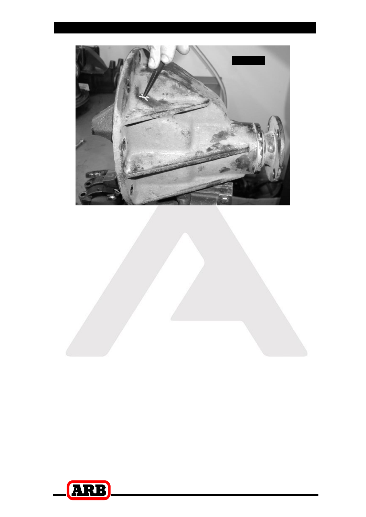
2.4 Marking the Bearing Caps
Using a small pointed center punch, gently mark the bearing caps
in a way that will enable you to know which cap is ‘LEFT’ and which
cap is ‘RIGHT’, which way is ‘UP’ and which way is ‘DOWN’.
(Fig.1.)
Mark the right hand cap in a similar way.
HINT : Many installers choose to make one punch mark on
the left hand side of the left hand bearing cap and a
similar mark on the housing at close proximity to the
cap mark. The right hand side is then designated with
two punch marks on the right hand side of the cap and
two similar punch marks on the housing.
Figure
1.

2 Removing the Existing Differential
7
2.5 Checking the Current Backlash Amount
IMPORTANT:
This step is a precautionary measure recommended by ARB due
to the fact that some after market ring and pinion sets have been
manufactured to run with different backlash settings than those
specified by your vehicle manufacturer. Although ARB must
recommend you set backlash according to your service manual
guidelines, we also advise that you compare the backlash
measurements taken here to the recommended backlash settings
in your vehicle service manual. Measurements found to be
outside of your service manual recommendations may indicate
the need to deviate from those settings in order to achieve quiet
running with a good contact mark.
Refer to your vehicle service manual or your local authorized
ARB installer for more information.
Set a dial indicator on one of the ring gear teeth. (Fig.2.)
Figure
2.
While supporting the pinion gear by holding the pinion flange, rotate
the differential in both directions while observing the maximum
variation in depth from the indicator (i.e., the highest value minus
the lowest value). This value is referred to as the ring and pinion
backlash.
Rotate the differential center 90and measure again for accuracy.
Record the average of all measurements.
2 Removing the Existing Differential
8
2.6 Removing the differential carrier
Remove the adjuster nut locking tabs.
Remove the bearing caps.
Loosen the adjuster nuts.
Carefully remove the differential carrier from the housing.
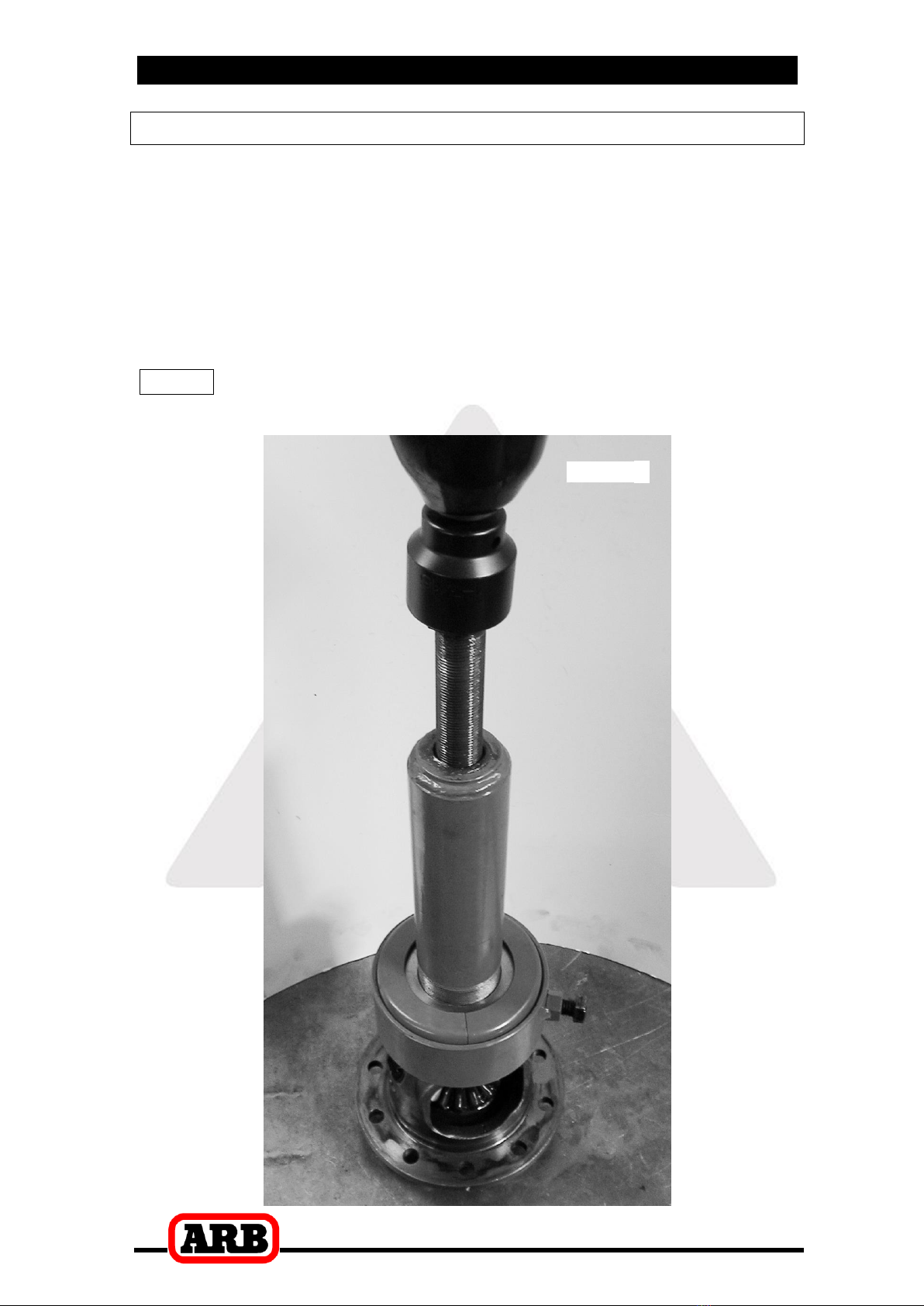
Remove the tapered roller bearings from the differential carrier with
a bearing puller. (Fig.3.)
HINT : Check the condition of the bearing for wear and
replace if necessary.
Figure
3.
3 Installing the Air Locker
9
3.1 Mounting the Ring Gear
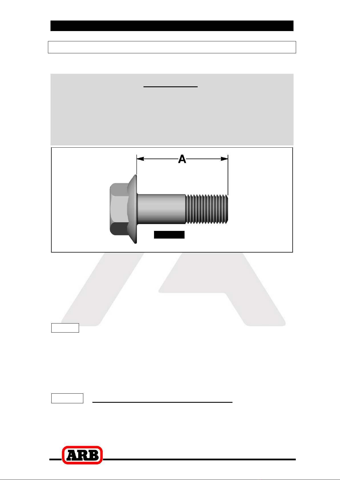
Remove the bolts that hold the ring gear in place.
IMPORTANT:
Two different bolt lengths were used on this model of Nissan
differential. Measure the length of the bolts you removed
(shown as ‘A’ in Figure 4.). Your Air Locker was designed to
use 30mm [1.18”] bolts. If your bolts are of a shorter series
(i.e., 25mm [0.98”] you will need to acquire the correct bolts
from Nissan.
Figure
4.
Using a plastic or copper hammer, tap in a circle around the ring
gear to separate it from the differential carrier.
Thoroughly clean any thread locking compound or other foreign
matter from the holes of the ring gear, the threads of the ring gear
bolts, the mating surfaces of the ring gear and the Air Locker
flange.
HINT : Rubbing the ring gear mounting face with a flat oil
stone before installation will remove any high spots
around the threads.
Heat the ring gear to between 80 and 100C (175 - 212F) in hot
water or in an oven to slightly expand the gear and facilitate
assembly.
NOTE : NEVER HEAT GEARS WITH A FLAME! This could
damage the hardened surface of the gear and result in
premature wear or failure.
3 Installing the Air Locker
10
Dry the gear and tapped holes with compressed air (if wet).
Apply a thin film of high-pressure grease to the ring gear shoulder
of the Air Locker to prevent seizing.
Install the ring gear onto the Air Locker by aligning the tapped holes
and then gently tapping it around in a circle with a soft mallet or
hammer. Avoid using the bolts to pull the ring gear down as this
puts excess strain on the bolts and the differential flange.
Apply a thread locking compound to the thread of each ring gear
bolt before inserting it. Do not apply locking compound directly into
the threaded hole as this could prevent the bolt from reaching its
full depth.
NOTE : On some models, the crown wheel bolts cannot be
reused and should therefore be replaced. Refer to
your vehicle manufacturer’s service manual for
details.
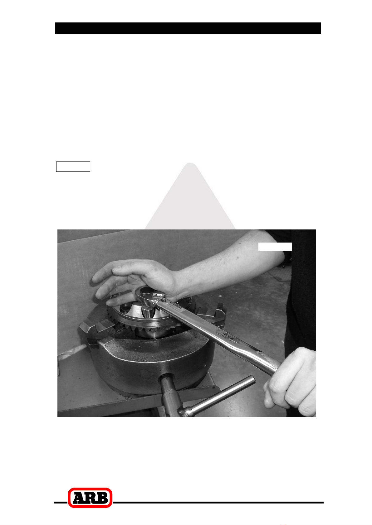
Tighten the ring gear bolts in a star pattern with a torque wrench
(Fig.5.) set to your vehicle manufacturer’s specified torque.
Figure
5.

3 Installing the Air Locker
11
3.2 Installing the Carrier Bearings
Apply a thin film of high pressure grease to the bearing journals of
the Air Locker, then press the bearing cones onto the bearing
journals as shown in Figure 6.
Figure
6.
3.3 Drilling and Tapping the Bulkhead Port
An air line port must be drilled and tapped through the differential
housing to mount the bulkhead fitting into.
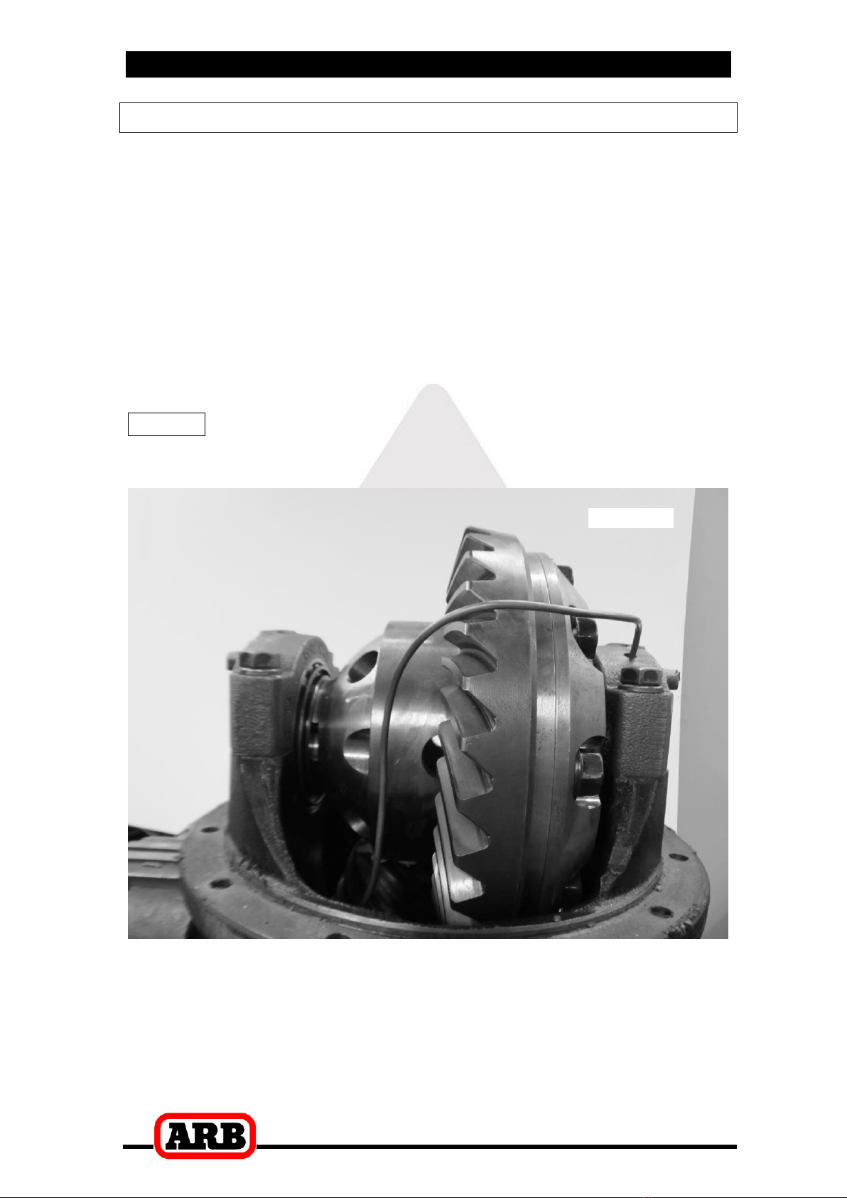
Mark a spot on the right hand side (opposite the ring gear) toward
the top of the differential housing that is in an area well clear of the
differential, the ring gear, and any other obstructions that could
snag the seal housing tube. (Fig.7.)
3 Installing the Air Locker
12
Figure
7.
Cover the drive pinion and axle tube areas with a rag to protect
them from metal filings.
Drill an 11.2mm [7/16”] diameter hole through the differential
housing square to the outside surface.
Tap the hole from the outside using ¼”NPT thread tap.
Remove any sharp edges that may chip off from around the hole
and fall into the housing.
Very carefully, remove the rags and inspect with a service light
inside the housing to ensure no metal filings are left behind.
3 Installing the Air Locker
13
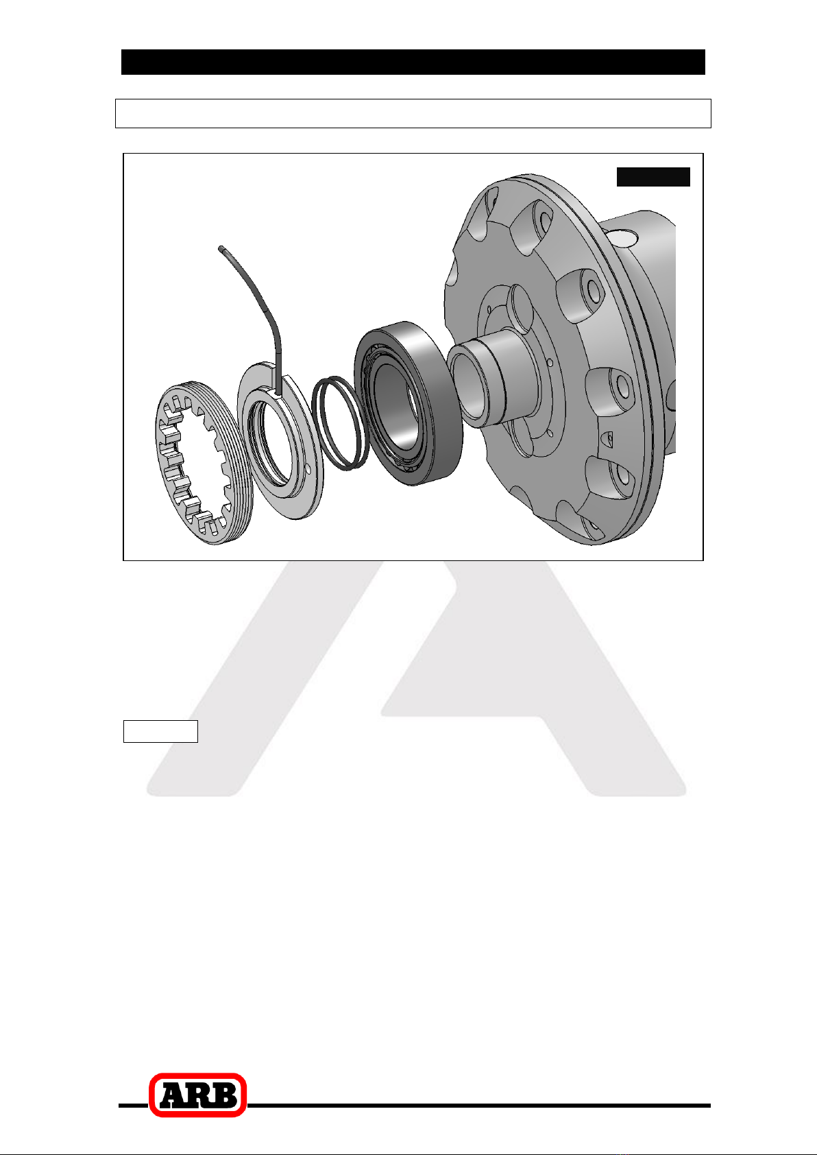
3.4 Assembling the Seal Housing
Figure
8.
Make sure the grooves and airway of the seal housing are clean
and free from any contaminants (e.g. water, dirt, metal filings, etc.).
Inspect the seal housing O-rings (supplied) for dirt, damage or
other conditions which might cause leaks.
Generously lubricate the O-rings with oil prior to assembly, then
insert them into the grooves of the seal housing.
NOTE : When assembling the O-rings, be careful not to leave
them twisted when seated in the grooves as this could
cause excessive wear and leakage.
Lubricate the seal housing running surface on the Air Locker carrier
with oil. Assemble the bearing cup onto the left-hand side of the Air
Locker.
Carefully install the seal housing by sliding it all of the way onto the
bearing journal with a gentle twisting motion. This will allow the O-
rings to engage gently (Fig. 8.).
3 Installing the Air Locker
14
3.5 Modifying the Bearing Cap
A 6.35mm [1/4”] hole must be drilled in the seal housing bearing
cap for the seal housing tube to pass through.
Clean all parts of the differential assembly.
Place the Air Locker into the differential housing, and using the
adjuster nuts, position the diff in approximately the correct position.
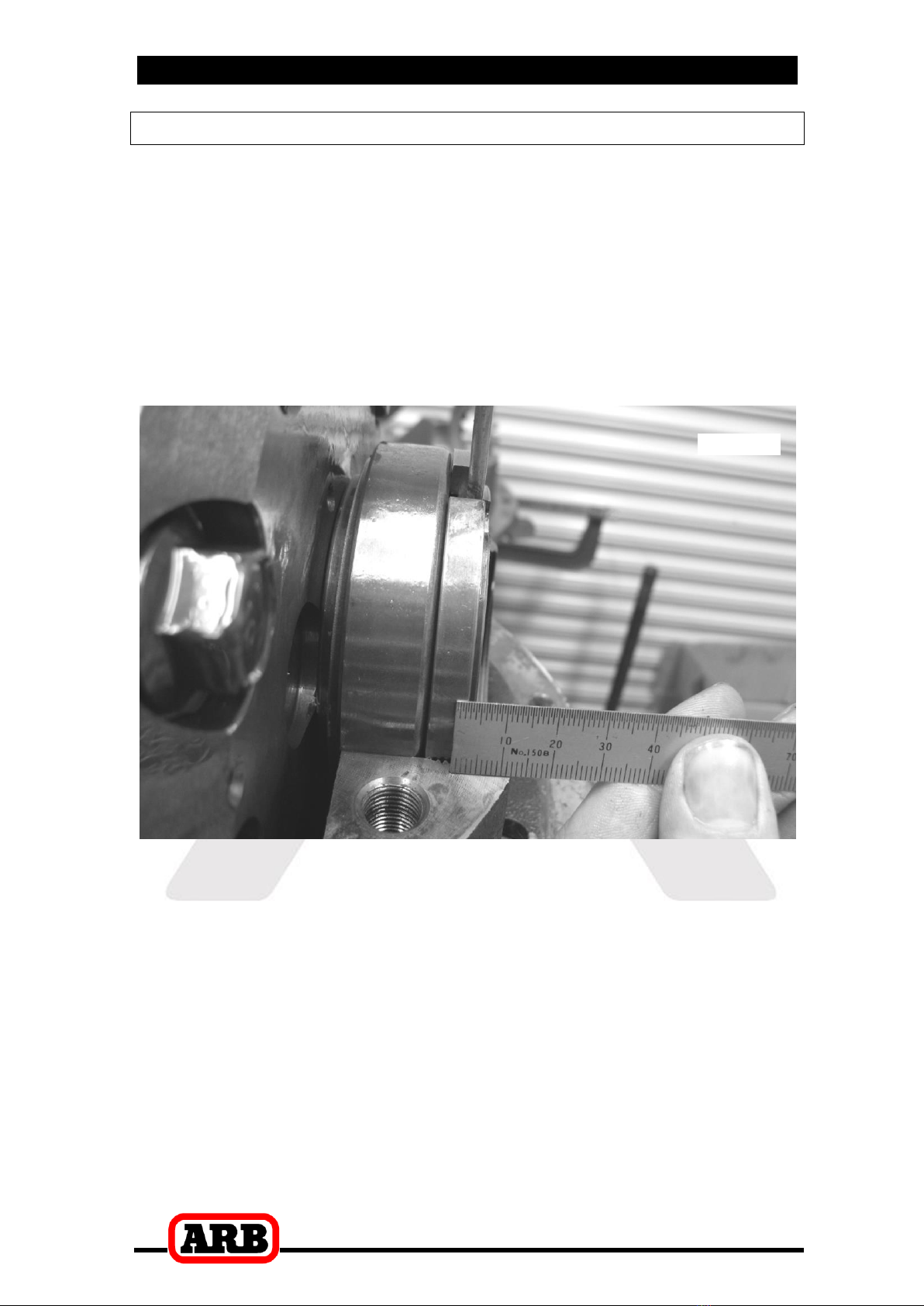
Measure the distance from the outside edge of the left hand
bearing cap, to the centerline of the seal housing tube as shown in
Fig 9. This measurement is required for positioning the hole. As can
be seen, in this example the distance is approximately 12mm.
Figure
9.

3 Installing the Air Locker
15
Remove the Air Locker from the housing.
Mark a spot on the bearing cap inline with the distance you
measured earlier (Fig. 10.) (approx. 30° from the adjuster nut lock
tab bolt hole).
Figure
10.
Using a soft jawed vice clamp, setup the bearing cap for drilling the
hole at the angle shown (Fig. 11.).
Figure
11.
3 Installing the Air Locker
16
NOTE : Take time and double check when drilling, as bearing
caps are custom fitted to the axle housing and cannot
be replaced.
NOTE : Do not apply too much clamping pressure with the
vice. The bearing cap may be damaged.
Using a pedestal drill, drill a 6.35mm [¼’’] hole through the bearing
cap, in the position shown.
Debur both ends of the drilled hole to remove any sharp edges.
3.6 Final Air Locker Assembly
Place the Air Locker into the differential housing, ensuring that the
seal housing tube will line up with the hole in the bearing cap, and
install the bearing caps (Fig. 11.)
NOTE : Be sure to check that the bearing caps are on the
correct sides of the third member and are correctly
aligned.
Insert the bearing cap bolts and hand tighten.
NOTE : Before attempting to install the adjuster nuts, make
sure the threads on the inside of the bearing caps and
differential housing are perfectly aligned. If they are
not, the threads could be stripped.
Insert and lightly hand tighten the ring gear side adjuster nut into
the ring gear side bearing cap.
NOTE : You should feel no backlash between the ring and
pinion gears once the adjuster nut tightens.
Reverse the adjuster nut (counterclockwise) ¼ turn.
Insert the case side adjuster nut onto the opposite side of the
differential and tighten and preload with the appropriate adjuster nut
wrench.
NOTE : You should now feel some backlash between the ring
and pinion gears. If not, there might be a clearance
problem which is binding the carrier. Re-check the
clearance.
NOTE : Preload the bearings using the case side adjuster nut
so as not to risk damage to the seal housing.
3 Installing the Air Locker
17
3.7 Setting up the Bulkhead Fitting
Apply thread sealant to the outside threads of the bulkhead body.
Screw the bulkhead body into the tapped hole, and lightly tighten
using a 14mm [9/16”] spanner.
Wipe the area clean of any excess thread sealant (inside and
outside of the housing).
Without using sharp, jagged tools such as pliers (your hands are
the best tool for this job), bend the seal housing tube to
approximate the finished profile. This will allow the tube to be
trimmed to a length that would allow it to protrude from the
bulkhead fitting. (Fig. 12.)
NOTE : Use an automotive brake line tubing cutter to cut the
seal housing tube, never a hacksaw as this will leave
metal filings in the air system.
Figure
12.
Insert the free end of the seal housing tube into the bulkhead fitting
until it protrudes approximately 8mm [5/16”] through the other side.
From the outside of the housing, assemble one of the small O-rings
over the top of the short length of seal housing tube protruding
through the bulkhead fitting.
3 Installing the Air Locker
18
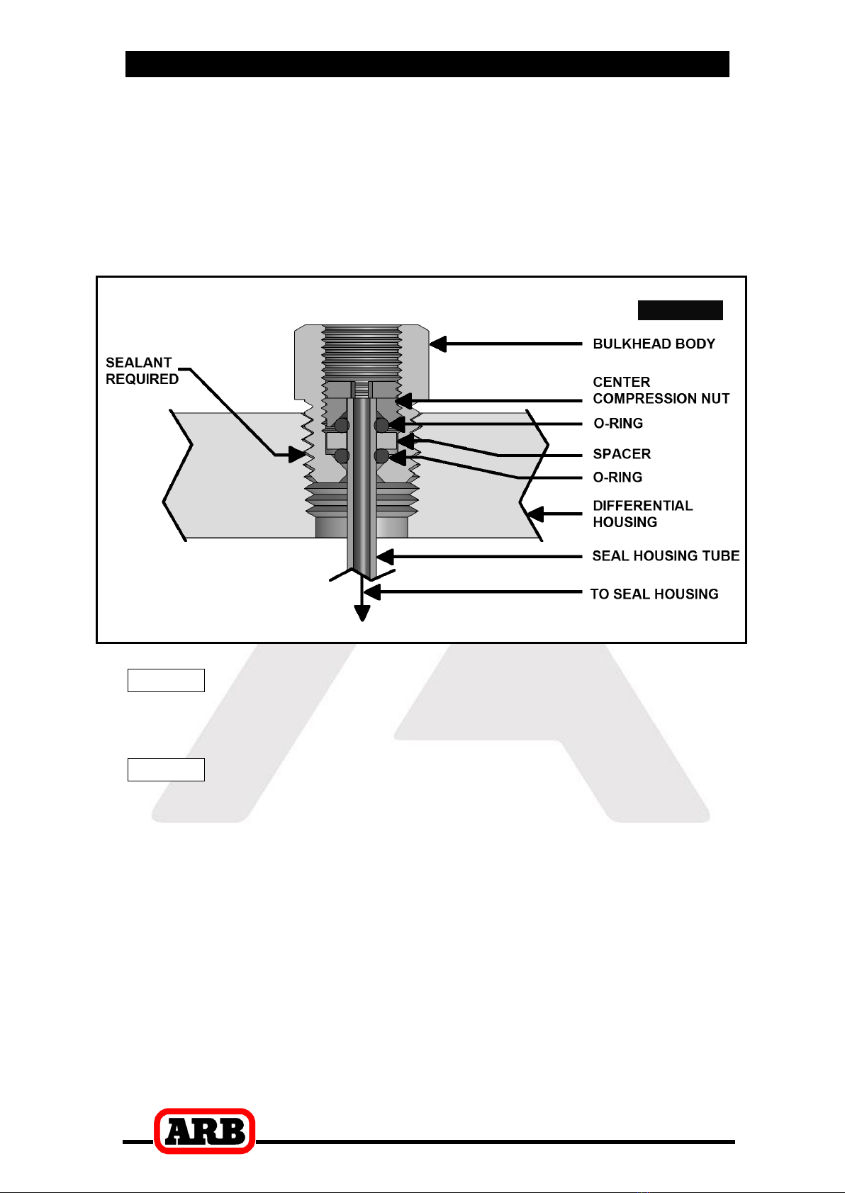
Install the brass spacer.
Install the second small O-ring after the spacer.
While holding the seal housing tube into the bulkhead fitting, insert
the chamfered end of the center compression nut over the
extended tube as shown in the assembly diagram (Fig. 13.), and
screw it into the bulkhead body, and tighten using Pozidriv #3
screwdriver.
Figure
13.
NOTE : Make sure the seal housing tube is all of the way into
the center compression nut while you are tightening
it.
NOTE : Firmly tighten the center compression nut so that a
good seal is formed around the tube.
Table of contents
Other ARB Automobile Accessories manuals


ARB
ARB AIRLOCKER RD132 User manual

ARB
ARB Airlocker RD210 User manual

ARB
ARB AC08C User manual

ARB
ARB AIRLOCKER RD142 User manual

ARB
ARB RD116 User manual

ARB
ARB Airlocker RD146 User manual

ARB
ARB Airlocker RD205 User manual

ARB
ARB AIRLOCKER RD208 User manual

ARB
ARB Airlocker RD167 User manual

ARB
ARB 3434040 User manual


