AEG WS 700-100 User manual

WS 700-100, WS 700-115, WS 700-125,
WSE 700-115
Instruction for use
Please read and save these instruction
Gebrauchsanleitung
Bitte lesen und aufbewahren
Instruction d’utilisation
Prière de lire et de conserver
Istruzioni d’uso
Si prega di leggere le istruzioni e di conservarle
Instrucciones de uso
Lea y conserve estas instricciones por favor
Instruções de serviço
Por favor leia e conserve em seu poder
Gebruiksaanwijzing
Lees en let goed op deze advizen
Brugsanvisning
Vær venlight at læse og opbevare
Bruksanvisning
Vennligst les og ta godt vare pådenne informasjonen
Bruksanvisning
Var god läs och tag tillvara dessa instruktioner
Käyttöohje
Lue ja säilytö

ENGLISH # WS 700-100, WS 700-115, WS 700-125, WSE 700-115
Introduction You demand the best and buy quality - quality provided by Atlas Copco. We have
built for you a reliable and lasting tool. Working effectively and without endangering
your health is only possible if this instruction for use is read carefully before first us-
ing the tool. We want to satisfy our customers and would like you to buy again AEG
Electric Power Tools from Atlas Copco.
Technical Data
Safety advice ■Please note safety instructions on red sheet 4 000 333 024!
■Do not pierce the motor housing as this could damage the double insulation (use
adhesives).
■Always pull the plug from the mains before making any settings or carrying out main-
tenance.
■Only plug-in when machine is switched off.
■Keep mains lead clear from working range of the machine. Always lead the cable
away behind you.
■Before use check machine, cable, and plug for any damages or material fatigue. Re-
pairs should only be carried out by authorised service agents.
■After switching off, the machine will not be idle immediately. (After-running of the
work spindle.) Allow the machine to come to a stop before putting down.
■Never reach into the danger area of the machine when it is running.
■Always wear safety goggles and ear protectors when working with this machine. It
is further recommended to wear safety gloves, apron, as well as sturdy non-slipping
shoes.
■Always use the additional handle.
■Always use the protecting cap when roughing-down and separating.
■Only use tools whose permitted speed is at least as high as the highest no-load
speed of the machine.
■Pay attention to the dimensions of the grinding disc. The mounting hole diameter
must fit the mounting flange without play. Do not use reducer pieces or adapters.
■Check grinding tools before use. The grinding tool must be properly mounted and
turn freely. Perform a test run for at least 30 seconds without load. Do not use dam-
aged, out of round or vibrating grinding tools.
■Immediately switch off the machine in case of considerable vibrations or if other mal-
functions occur. Check the machine in order to find out the cause.
■Always use and store the grinding disks according to the manufacturer’s instruc-
tions.
■When grinding metal, flying sparks are produced. Take care that no persons are en-
dangered. Because of the danger of fire, no combustible materials should be locat-
ed in the vicinity (spark flight zone). Do not use dust extraction.
■Due care should be taken that no sparks or sanding dust flying from the workpiece
come into contact with you.
Type WS 700-100 WS 700-115 WS 700-125 WSE 700-115
Nominal power (W) 710 710 710 710
Min. no-load speed (min-1)2700
Max. no-load speed (min-1) 11000 10000 10000 10000
Grinding disk diameter (mm) 100 115 125 115
Thread of work spindle M10 M14 M14 M14
Weight (kg) 1.6 1.6 1.6 1.6
Speed control ––– •
No-load speed limiter ––– •
Smooth start ––– •

ENGLISH # WS 700-100, WS 700-115, WS 700-125, WSE 700-115
■Dust that arises when working in stones with crystalline silicic acid can damage your
health. Do not work on any material containing asbestos. Please note the safety reg-
ulations, VBG, of the employer’s liability insurance association.
■Never use a cutting disc for grinding. Do not subject cutting discs to side pressure.
■When separating stone the guide shoe must be used!
■The adjusting nut must be tightened before starting to work with the machine.
■The workpiece must be fixed if it is not heavy enough to be steady. Never lead the
workpiece to the grinding disk with your hand.
■In case of extreme operating conditions (e.g. when smoothing metals with the sup-
porting disk and vulcanised fibre disks) strong contamination can build up inside the
angle grinder. In such cases it is recommended to shorten the cleaning cycles and/
or add a residual current operated device.
Measured
sound value Typically the A-weighted noise levels of the tool are:
Sound pressure level = 85 dB (A).
Sound power level = 98 dB (A).
Wear ear protectors!
Measured
vibration value Typically the weighted acceleration is 5 m/s2.
Usage This angle grinder can be used for separating and grinding many different materials,
e.g. metal or stone. In case of doubt please read the manufacturers’instruction.
Do not use this product in any other way as stated for normal use.
Mains
connection Connect only to a single-phase AC current supply and only to the mains voltage
specified on the rating plate. Connection to sockets without earth protection is pos-
sible as the appliance features protective insulation to DIN 57 740/ VDE 0740 and
CEE 20. Radio suppression complies with the European standard EN 55014.
When fitting the plug, make sure that the brown (live) wire of this appliance is con-
nected to the plug terminal marked L or coloured red, and the blue (neutral) wire of
this appliance is connected to the plug terminal marked N or coloured black. Under
no circumstances must the wires of this appliance be connected to the earth termi-
nal of the plug marked either E, with the earth symbol, or coloured green or green/
yellow.
Smooth start
(WSE 700-115) The electronic smooth start will prolong the life of both the motor and the gears.
Switching on
and off Switchingon: Pushtheslidingswitchforward.To
lock, depress the front part of the switch.
Switching off: To unlock, depress the back part
of the sliding switch. The switch will automatically
move back to “O”.
1
2

ENGLISH # WS 700-100, WS 700-115, WS 700-125, WSE 700-115
Modifications: Text, diagrams and data are correct at the time of printing. In the interest of continuous
improvement of our products, technical specifications are subject to alteration without prior notice.
Spindle lock
Direction of rotation arrow
Work spindle
On/Off switch with
locking device
No-load speed limit for low-noise
operation
(only applicable for WSE 700-115)
Electronic speed adjustment ensures constant
speed even when the load on the motor varies
(only applicable for WSE 700-115)
Working tool
Brief
description
Additional side
handle
Protective guard
with clamping
screw
Tension flange
Adjusting nut
Pin-type face spanner
Speed adjustment knob
(only applicable for WSE 700-115)

ENGLISH # WS 700-100, WS 700-115, WS 700-125, WSE 700-115
Electronics The speed of rotation is adjusted electronically when the load increases.
Under the effect of extreme electromagnetic interferences from the outside, tempo-
rary variations in the speed of rotation could arise in particular cases.
Speed selection
(WSE 700-115) Speed pre-selection with the setting wheel:
A = lowest speed
G = highest speed
Mounting the
protective cap Slide the protective guard onto the clamping col-
lar. If necessary, loosen the clamping screw some
turns.
Position the protective guard according to the re-
quirements and tighten the clamping screw until
the protective guard is firmly seated.
With the clamping screw tightened, the protective
guard should no longer be able to be moved. Take
care that the grinding disk can be freely turned.
Fitting the
working tool Always disconnect the plug from the socket before carrying out any work on the
machine.
Lock the work spindle by depressing the spindle
lock. Mount the tension flange, the working tool,
and the adjusting nut as shown in illustration.
Loosen respectively tighten the djusting nut with a
pin-type face spanner.

ENGLISH # WS 700-100, WS 700-115, WS 700-125, WSE 700-115
Advices for
operation
When grinding do not apply pressure on the tool but use it with gentle reciprocating
movements.
Rough grinding For best results when roughing-down keep the disk at an angle ofat least 30°to the
working surface.
Overloading the machine when grinding will damage the angle grinder and results
in faster wearing out of the disks. Grinding performance will suffer.
Never use a cutting disc for grinding. Do not subject cutting discs to side pressure.
Separating Do not tilt the angle grinder when separating. The cutting disk must have a clean
edge.
When separating stone the guide shoe must be used!
Surface grinding When surface grinding use a plastic backing pad with an abrasive disk.
For removing rust or old coats of paint it is recommended to use a steel brush
(saucepan brush).
Optimum speed
of rotation
(WSE 700-115)
The optimum speed of rotation also depends on the hardness of the material to be
worked as well as the quality of the used working tool:
Service Keep the machine and the ventilation slots clean.
Use only AEG accessories and spare parts. Should components need to be re-
placed which have not been described, please contact one of our AEG service
agents (see our list of guarantee/service addresses).
If needed, an exploded view of the tool can be ordered. Please state the ten-digit
No. as well as the machine type printed on the label and order the drawing at your
local service agents or directly at:
Atlas Copco Electric Tools GmbH, Postfach 320, D-71361 Winnenden.
Accessories The range of accessories and their part numbers are shown in our catalogue.
Usage Electronics
Sanding of plastics with backing pad and abrasive paper A-C
Sanding wood and removal of paint with backing pad and abrasive
paper B-D
Sanding of metal with backing pad and abrasive paper C-F
Removal of rust from metal with steel-wire brushes D-F
Grinding of steel, Cutting steel and stone G
Polishing with backing pad and lambswool bonnet A-B

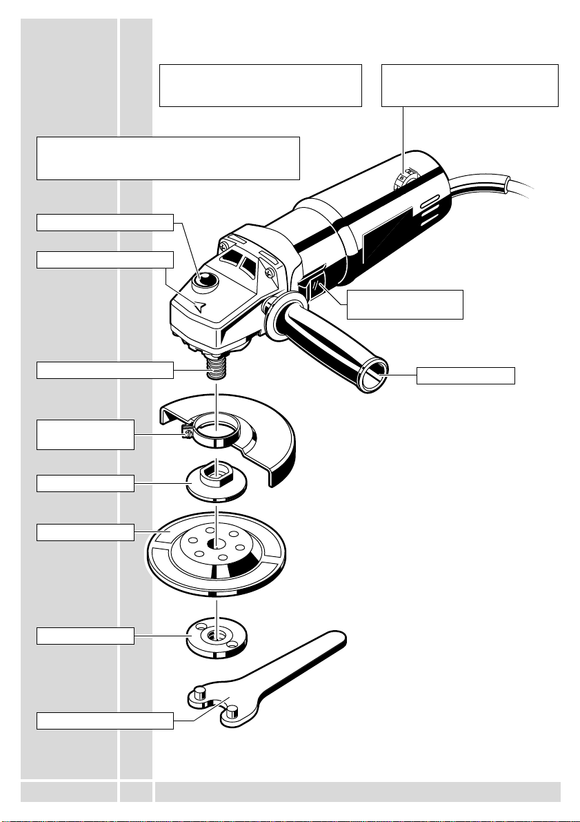
DEUTSCH 7 WS 700-100, WS 700-115, WS 700-125, WSE 700-115
Vorwort Sie sind anspruchsvoll und kaufen Qualität - Qualität von Atlas Copco. Wir haben
fürSieeinhaltbaresund möglichstsicheresElektrowerkzeug gebaut.Effektivesund
weitgehend gefahrloses Arbeiten ist aber nur möglich, wenn Sie diese Gebrauchs-
anleitung lesen und danach handeln. Wir wollen, daßSie sich auch in Zukunft ent-
scheiden für AEG-Elektrowerkzeuge von Atlas Copco.
Technische
Daten
Hinweise für
Ihre Sicherheit ■Sicherheitshinweise auf rotem Beiblatt (4 000 333 024) beachten!
■Gehäuse der Maschine nicht anbohren, da sonst die Schutzisolierung unterbrochen
wird (Klebeschilder verwenden).
■Stecker aus der Steckdose ziehen, bevor irgendeine Einstellung oder Wartung vor-
genommen wird.
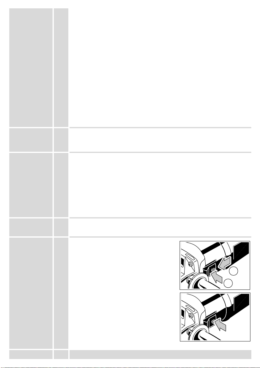
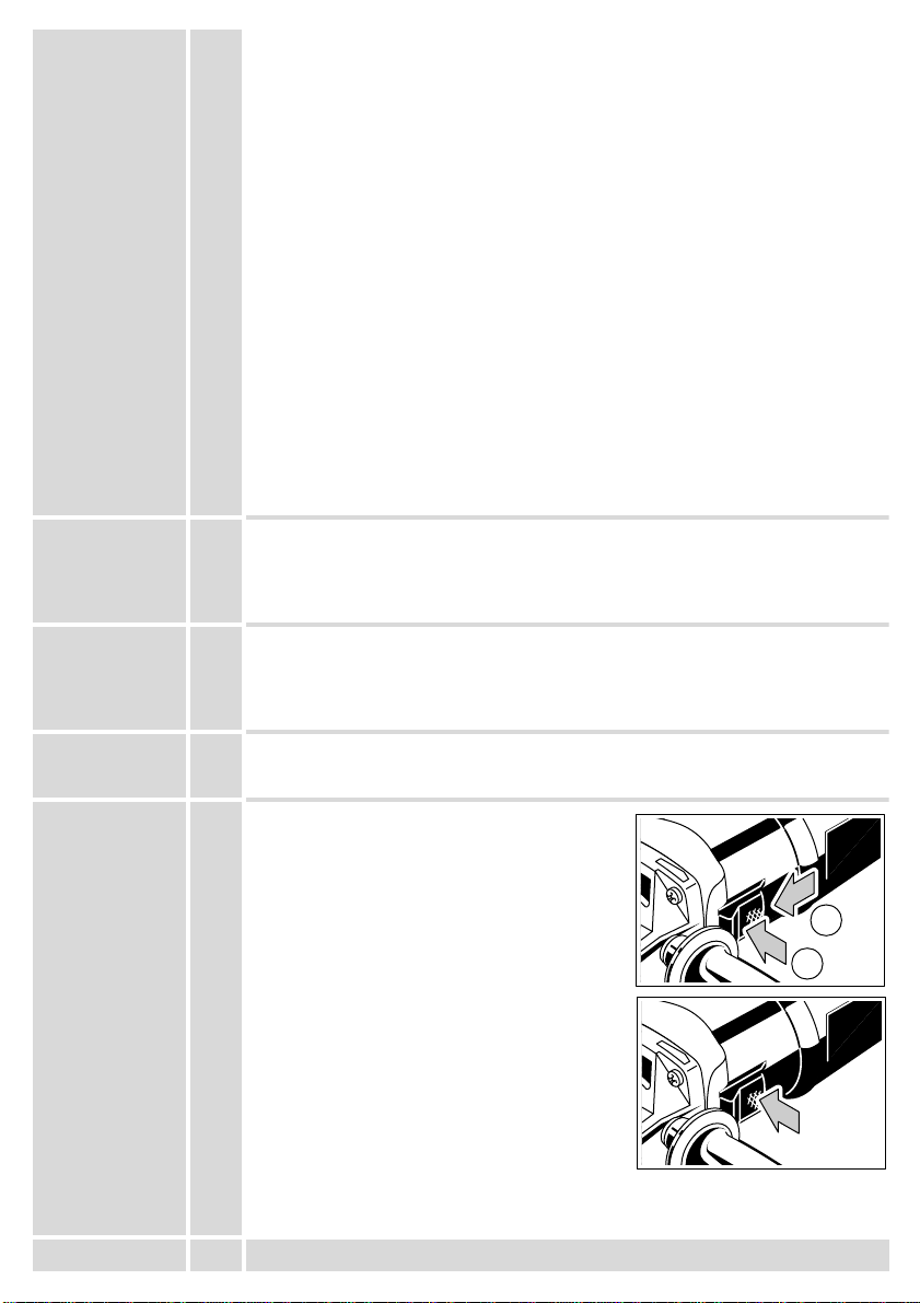
■Maschine nur ausgeschaltet an die Steckdose anschließen.
■Anschlußkabel stets vom Wirkungsbereich der Maschine fernhalten. Kabel immer
nach hinten von der Maschine wegführen.
■Vor jedem Gebrauch Gerät, Anschlußkabel, Verlängerungskabel und Stecker auf
Beschädigung und Alterung kontrollieren. Beschädigte Teile nur von einem Fach-
mann reparieren lassen.
■Die Werkzeugspindel läuft nach, nachdem das Gerät ausgeschaltet wurde. Maschi-
ne erst nach Stillstand ablegen.
■Nicht in den Gefahrenbereich der laufenden Maschine greifen.
■Beim Arbeiten mit der Maschine stets Schutzbrille und Gehörschutz tragen. Schutz-
handschuhe, festes und rutschsicheres Schuhwerk und Schürze werden empfohlen.
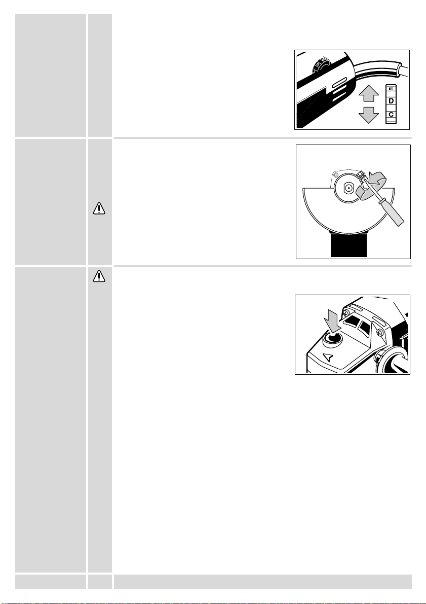
■Stets den Zusatzhandgriff verwenden.
■Beim Schruppen und Trennen immer mit Schutzhaube arbeiten.
■Nur Arbeitswerkzeuge verwenden, deren zulässige Drehzahl mindestens so hoch
ist wie die höchste Leerlaufdrehzahl des Gerätes.
■Abmessungen der Schleifscheiben beachten. Lochdurchmesser mußohne Spiel
zum Aufnahmeflansch passen. Keine Reduzierstücke oder Adapter verwenden.
■Schleifwerkzeuge vor dem Gebrauch überprüfen. Das Schleifwerkzeug mußein-
wandfrei montiert sein und sich frei drehen können. Probelauf mindestens 30 Se-
kunden ohne Belastung durchführen. Beschädigte, unrunde oder vibrierende
Schleifwerkzeuge nicht verwenden.
■Gerät sofort ausschalten, wenn beträchtliche Schwingungen auftreten oder andere
Mängel festgestellt werden. Überprüfen Sie die Maschine, um die Ursache festzu-
stellen.
■Schleifscheiben stets gemäß den Angaben des Herstellers verwenden und aufbe-
wahren.
■Beim Schleifen von Metallen entsteht Funkenflug. Darauf achten, daßkeine Perso-
nen gefährdet werden. Wegen der Brandgefahr dürfen sich keine brennbaren Ma-
terialien in der Nähe (Funkenflugbereich) befinden. Keine Staubabsaugung
verwenden.
Typ WS 700-100 WS 700-115 WS 700-125 WSE 700-115
Nennaufnahme (W) 710 710 710 710
min. Leerlaufdrehzahl (min-1)2700
max. Leerlaufdrehzahl (min-1) 11000 10000 10000 10000
max. Schleifscheiben-Ø(mm) 100 115 125 115
Spindelgewinde M10 M14 M14 M14
Gewicht (kg) 1,6 1,6 1,6 1,6
Drehzahlsteuerung –––•
Drehzahlbegrenzung ––– •
Sanftanlauf ––– •

DEUTSCH 8 WS 700-100, WS 700-115, WS 700-125, WSE 700-115
■Gerät immer so halten, daßFunken oder Schleifstaub vom Körper wegfliegen.
■Staub, der bei der Bearbeitung von Gestein mit kristalliner Kieselsäure entsteht, ist
gesundheitsschädlich. Asbesthaltiges Material darf nicht bearbeitet werden. Beach-
ten Sie die Unfallverhütungsvorschriften VBG 119 der Berufsgenossenschaft.
■Niemals Trennscheiben zum Schruppschleifen verwenden.Trennscheiben keinem
seitlichen Druck aussetzen.
■Zum Trennen von Stein ist der Führungsschlitten Vorschrift.
■Die Flanschmutter mußvor Inbetriebnahme der Maschine angezogen sein.
■Das zu bearbeitende Werkstück mußfestgespannt werden, sofern es nicht durch
sein Eigengewicht hält. Niemals Werkstück mit der Hand gegen die Scheibe führen.
■Bei extremen Einsatzbedingungen (z. B. beim Glattschleifen von Metallen mit dem
Stützteller und Vulkanfieber-Schleifscheiben) kann sich eine starke Verschmutzung
im Inneren des Winkelschleifers aufbauen. Es empfiehlt sich in solchen Fällen eine
Verkürzung der Reinigungszyklen und/oder das Vorschalten eines Fehlerstrom-
(FI-)Schutzschalters.
Geräusch-
meßwerte Der A-bewertete Geräuschpegel des Gerätes beträgt typischerweise:
Schalldruckpegel = 85 dB (A).
Schalleistungspegel = 98 dB (A).
Gehörschutz tragen!
Vibrations-
meßwerte Die bewertete Beschleunigung beträgt typischerweise 5 m/s2.
Verwendung Der Winkelschleifer ist einsetzbar zum Trennen und Schleifen von vielen Materiali-
en, wie z. B. Metall oder Stein. Beachten Sie im Zweifelsfall die Hinweise der
Schleifwerkzeughersteller.
Dieses Gerät darf nur wie angegeben bestimmungsgemäß verwendet werden.
NetzanschlußNur an Einphasen-Wechselstrom und nur an die auf dem Leistungsschild
angegebene Netzspannung anschließen. Anschlußist auch an Steckdosen ohne
Schutzkontakt möglich, da eine Schutzisolierung nach DIN 57 740/ VDE 0740 bzw.
CEE 20 vorliegt. Die Funkentstörung entspricht der Europanorm EN 55014.
Sanftanlauf
(WSE 700-115) Der elektronische Sanftanlauf erhöht die Lebensdauer von Motor und Getriebe, der
Einschaltstrom wird um ca. die Hälfte reduziert.
Ein-/
Ausschalten Einschalten: Schiebeschalter nach vorne schie-
ben und zum Arretieren im vorderen Bereich nach
unten drücken.
Ausschalten: Schiebeschalter im hinteren Be-
reich nach unten drücken. Der Schalter geht auto-
matisch zurück in die 0-Stellung.
1
2

DEUTSCH 9 WS 700-100, WS 700-115, WS 700-125, WSE 700-115
Änderungen: Text, Bild und Daten entsprechen dem technischen Stand zur Zeit des Drucktermins.
Änderungen im Sinne der Weiterentwicklung unserer Produkte sind vorbehalten.
Spindelarretierung
Drehrichtungspfeil
Arbeitsspindel
Ein-/Ausschalter mit
Arretierung
Leerlaufdrehzahlbegrenzung für
geräuscharmen Lauf
(nur bei WSE 700-115)
Konstante Drehzahl bei unterschiedlich starker
Motorbelastung durch Regelelektronik.
(nur bei WSE 700-115)
Arbeitswerkzeug
Kurz-
beschreibung
Zusatzhandgriff
Schutzhaube mit
Spannschraube
Spannflansch
Flanschmutter
Zweiloch-Mutterndreher
Drehzahlstellrad
(nur bei WSE 700-115)

DEUTSCH 10 WS 700-100, WS 700-115, WS 700-125, WSE 700-115
Elektronik Die Elektronik regelt die Drehzahl bei steigender Belastung nach.
Unter Einwirkung extremer elektromagnetischer Störungen von außen, können im
Einzelfall vorübergehende Drehzahlschwankungen auftreten.
Drehzahl
vorwählen
(WSE 700-115)
Drehzahlvorwahl mit Stellrad:
A= kleinste Drehzahl
G= größte Drehzahl
Schutzhaube
montieren Schutzhaube auf Spannhals schieben, falls erfor-
derlich dazu die Spannschraube einige Gewinde-
gänge lösen.
Schutzhaube entsprechend den Anfordernissen
ausrichtenundSpannschraubefestziehen,bisdie
Schutzhaube fest sitzt.
Die Schutzhaube darf sich bei geschlossener
Spannschraube nicht mehr verschieben lassen.
Darauf achten, daßsich die Schleifscheibe frei
drehen läßt.
Arbeitswerk-
zeug einsetzen Vor allen Arbeiten an der Maschine Stecker aus der Steckdose ziehen.
Arbeitsspindel durch Drücken auf die Spindelarre-
tierung feststellen. Spannflansch, Arbeitswerk-
zeug und Flanschmutter entsprechend der
Abbildung montieren.
Flanschmutter mit Zweilochschlüssel öffnen bzw.
anziehen.

DEUTSCH 11 WS 700-100, WS 700-115, WS 700-125, WSE 700-115
Arbeitshinweise Beim Schleifen nicht in das Werkstück hineindrücken, sondern Schleifscheibe
gleichmäßig über das Werkstück hin und her bewegen.
Schrupp-
schleifen Die beste Wirkung beim Schruppschleifen wird erreicht, wenn die Schleifscheibe in
einem Winkel von mindestens 30°zur Schleifebene angesetzt wird.
Zu starke Belastung während des Schleifens schadet dem Winkelschleifer und er-
höht den Schleifscheibenverbrauch, die Schleifleistung wird schlechter.
Niemals Trennscheiben zum Schruppschleifen verwenden.Trennscheiben keinem
seitlichen Druck aussetzen.
Trennschleifen Bei Trennarbeiten Winkelschleifer in der Schleifebene nicht verkanten. Die Trenn-
scheibe mußeine saubere Schnittkante aufweisen.
Zum Trennen von Stein ist der Führungsschlitten Vorschrift.
Flächenschleifen Zum Flächenschleifen Kunststoffschleifteller mit Schleifblatt verwenden.
Zum Entfernen von Rost oder alten Farbanstrichen eignet sich eine Stahldrahtbür-
ste (Topfbürste).
Richtige
Arbeitsdrehzahl
(WSE 700-115)
Die optimale Drehzahl hängt unter anderem von der Härte des zu bearbeitenden
Materials sowie von der Qualität und Art des Arbeitswerkzeugs ab:
Wartung Gerät und Lüftungsschlitze stets sauber halten.
Nur AEG-Zubehör und Ersatzteile verwenden. Bauteile, deren Austausch nicht be-
schrieben wurde, bei einer AEG-Kundendienststelle auswechseln lassen (Broschü-
re Garantie/Kundendienstadressen beachten).
Bei Bedarf kann eine Explosionszeichnung des Gerätes unter Angabe der Maschi-
nen Type und der zehnstelligen Nummer auf dem Leistungsschild bei Ihrer Kunden-
dienststelle oder direkt bei Atlas Copco Electric Tools GmbH, Postfach 320,
D-71361 Winnenden angefordert werden.
ZubehörDas Zubehör mit Bestellnummern ersehen Sie bitte aus unseren Katalogen.
Anwendung Elektronik
Schleifen von Kunststoffen mit Schleifteller und Schleifblatt A-C
Schleifen von Holz und Entfernen von Farbe mit Schleifteller und
Schleifblatt B-D
Schleifen von Metall und Spachtel mit Schleifteller und Schleifblatt C-F
Entrosten von Metall mit Stahldrahtbürste D-F
Schruppen von Stahl, Trennen von Stahl und Stein G
Polieren mit Schleifteller und Lammfellhaube A-B

FRANÇAIS 12 WS 700-100, WS 700-115, WS 700-125, WSE 700-115
Introduction Vous exigez ce qu’il y a de meilleur et vous achetez de la qualité- la qualitéofferte
par Atlas Copco. Vous vous êtes dotéd’un outil de qualitédurable. Ce n’est qu’en
lisant attentivement ces instructions avant d’utiliser l’outil que vous assurerez un tra-
vail efficace et sans risque. Nous tenons àsatisfaire notre clientèle et nous espé-
rons que vous achèterez encore des outils électriques AEG d’Atlas Copco.
Caractéristiques
techniques
Conseils de
sécurité■Respecter les consignes de sécuritédu feuillet 4 000 333 024!
■Ne pas percer le carter de la machine; ceci pourrait entraîner une détérioration de
l’isolation de protection (utiliser des autocollants).
■Retirer la fiche de la prise de courant avant d’effectuer un réglage quelconque ou
des travaux de maintenance.
■Ne raccorder la machine au réseau que si l’interrupteur est en position arrêt.
■Le câble d’alimentation doit toujours se trouver en dehors du champ d’action de la
machine. Toujours maintenir le câble d’alimentation àl’arrière de la machine.
■Toujours retirer la fiche de la prise d’alimentation secteur avant de procéder àdes
transformations ou travaux de maintenance.
■Après avoir éteint la machine, la broche porte-outil continue àtourner un peu. Ne
déposer la machine qu’après arrêt complet.
■Veillez àne jamais mettre les mains dans la zone de travail, ceci pouvant entraîner
des risques de blessures.
■Lors des travaux, toujours porter deslunettes de protection et descasques antibruit!
Il est recommandéde mettre des gants de protections, des chaussures solides à
semelle antidérapante ainsi qu’un tablier.
■Utiliser toujours la poignée complémentaire.
■Ne jamais travailler sans capot protecteur pour des travaux de tronçonnage et
d’ébarbage.
■N’utiliser que des outils dont la vitesse admissible correspond au moins àcelle de
la vitesse àvide maximale de la machine.
■Observer les dimensions des disques àrectifier.Le diamètre du trou central doit très
exactement correspondre àcelui du moyeu-flasque (pas de jeu). N’utiliser ni rac-
cords réducteurs ni adaptateurs.
■Toujours contrôler l’état d’un outil de rectification avant de l’utiliser. L’outil doit être
montéde façon irréprochable et pouvoir tourner librement. Effectuer une marche
d’essai sans charge pendant au moins 30 secondes. Ne jamais utiliser un outil en-
dommagé, tournant en faux-rond ou générateur de vibration.
■Arrêter la machine tout de suite lorsqu’il y a des vibrations importantes ou que
d’autres défauts surgissent. Contrôler la machine afin d’en trouver les causes.
■Toujours utiliser et conserver les meules conformément aux indications du produc-
teur.
■La rectification des métaux génère des étincelles. Veiller àce que personne ne soit
mis en danger. En raison du risque d’incendie, aucune matière inflammable ou com-
bustible ne doit se trouver dans la zone de projection des étincelles. Ne pas utiliser
d’aspirateur de poussières.
Type WS 700-100 WS 700-115 WS 700-125 WSE 700-115
Puissance absorbée (W) 710 710 710 710
Vitesse àvide min. (min-1)2700
Vitesse àvide max. (min-1) 11000 10000 10000 10000
Diamètre de disque max. (mm) 100 115 125 115
Filetage de l’arbre M10 M14 M14 M14
Poids (kg) 1,6 1,6 1,6 1,6
Commande de la vitesse ––– •
Limitation de vitesse ––– •
Démarrage progressif ––– •

FRANÇAIS 13 WS 700-100, WS 700-115, WS 700-125, WSE 700-115
■Toujours maintenir la machine de façon àce que étincelles et poussières soient
hors du portée du corps.
■La poussière qui se dégage lors de l’usinage des pierres contenant de l’acide silici-
que cristallin porte atteinte àla santé. Ne jamais travailler des matériaux contenant
de l’amiante. Respecter les consignes de sécuritédu syndicat professionnel. Res-
pecter les prescriptions relatives àla sécuritédu travail et àla prévention d’acci-
dents.
■Ne jamais utiliser de disques àtronçonner pour exécuter des travaux d’ébarbage.
Ne pas exercer de pression latérale sur un disque àtronçonner.
■Le chariot de guidage est obligatoire pour des travaux de tronçonnage de la pierre.
■L’écrou du flasque doit être serréavant de mettre en marche la machine.
■La pièce àtravailler doit être serrée rigidement lorsque son propre poids ne suffit
pas àla maintenir. Ne jamais guider àla main la pièce àtravailler vers la meule.
■Dans des conditions d’utilisation extrêmes (par exemple travaux de ponçage du mé-
tal avec disque d’appui et meule en fibre vulcanisée), l’intérieur de la meuleuse d’an-
gle peut s’encrasser rapidement. Dans de tels cas, il est recommandéde procéder
àun nettoyage plus fréquent et / ou de monter un disjoncteur différentiel.
Mesure de bruit Les mesures réelles (A) des niveaux de bruit de la machine sont:
Intensitéde bruit = 85 dB (A).
Niveau de bruit = 98 dB (A).
Toujours porter des casques antibruit protecteurs!
Valeur de vibra-
tion mesuréeL’accélération réelle mesurée est de 5 m/s2.
Utilisation La meuleuse d’angle peut être utilisée pour des travaux de tronçonnage et de pon-
çage de nombreux matériaux, comme le métal ou la pierre. En cas de doute, res-
pecter les indications du fabricant de l’outil.
Comme déjàindiqué, cette machine n’est conçue que pour une utilisation normale.
Branchement
secteur Nos machines fonctionnent uniquement sur courant alternatif monophasé. S’assu-
rer que la tension du réseau correspond effectivement àcelle indiquée sur la plaque
signalétique de la machine. Le branchement sur une prise de courant sans mise à
terre est possible du fait de la double isolation selon normes DIN 57 740/VDE 0740
et CEE 20. Antiparasitage selon normes européennes EN 55014.
Démarrage
progressif
(WSE 700-115)
Le démarrage progressif prolonge la durée de vie du moteur et de l’engrenage, le
courant de démarrage est réduit environ de moitié.
Marche/arrêt Mettre en marche: Pousser l’interrupteur àcou-
lisse vers l’avant et, pour le bloquer, pousser la
partie avant vers le bas.
Arrêt: Pousser la partie arrière vers le bas. L’in-
terrupteur se met automatiquement en position 0.
1
2

FRANÇAIS 14 WS 700-100, WS 700-115, WS 700-125, WSE 700-115
Modifications: Les textes, les illustrations et les données techniques correspondent àla situation au
moment de l’impression. Toutes modifications techniques sont réservées dans le cadre du développe-
ment technique permanent.
Blocage de l’arbre moteur
Sens de rotation
Arbre moteur
Interrupteur Marche/Arrêt
avec blocage
Limitation de vitesse àvide pour une
marche silencieuse
(uniquement sur WSE 700-115)
L’électronique de commande permet d’obtenir une
vitesse constante quel que soit le degréde sollicita-
tion du moteur (uniquement sur WSE 700-115)
Outil
Description
succinte
Poignée
complémentaire
Capot de
protection avec
vis de serrage
Flasque de
serrage
Ecrou du flasque
Cléàergots
Molette de réglage de la vitesse
(uniquement sur WSE 700-115)

FRANÇAIS 15 WS 700-100, WS 700-115, WS 700-125, WSE 700-115
Electronique L’électronique règle la vitesse de rotation conformément au degréde sollicitation.
En cas d’extrêmes perturbations électromagnétiques extérieures, il peut y avoir,
dans des cas isolés, des variations temporaires de la vitesse de rotation.
Présélection de
la vitesse
(WSE 700-115)
Présélection de la vitesse par molette:
A=Vitesseréduite
G=Vitesseélevée
Montage du
capot
protecteur
Monter le capot de protection sur le col de serra-
ge, si nécessaire desserrer légèrement la vis de
serrage.
Orienter le capot de protection suivant les be-
soins, puis serrer la vis de serrage jusqu‘à ce que
le capot de protection soit bien serré.
Lorsque la vis deserrage est bien serrée, le capot
de protection ne doit plus bouger. Veiller àce que
la meule puisse tourner librement.
Fixation de
l’outil Avant tous travaux sur la machine, la débrancher.
Bloquerl’arbre moteur en appuyant surle blocage
de l’arbre moteur. Monter le flasque de serrage,
l’outil et l’écrou du flasque conformément àla
figure.
Serrer et lâcher l’écrou du flasque àl’aide d’une
cléàergots.

FRANÇAIS 16 WS 700-100, WS 700-115, WS 700-125, WSE 700-115
Instructions
d’utilisation
Lors du travail ne pas exercer une trop grande pression sur l’outil mais guider la
meule de façon régulière sur la pièce àtravailler.
Travaux
d’ébarbage Lors des travaux d’ébarbage, la plus grande efficacitéest atteinte lorsque la meule
est posée àau moins 30°par rapport au plan de travail.
Unesollicitationtropélevéedurantletravail nuitàlamachine et provoqueuneusure
plus rapide des disques. La performance s’en trouve réduite.
Ne jamais utiliser de disques àtronçonner pour exécuter des travaux d’ébarbage.
Ne pas exercer de pression latérale sur un disque àtronçonner.
Travaux de
tronçonnage Lors des travaux de tronçonnage, ne pas tenir l’outil de biais par rapport au plan de
travail. La meule de tronçonnage doit présenter une arête de coupe irréprochable.
Le chariot de guidage est obligatoire pour des travaux de tronçonnage de la pierre.
Ponçage des
surfaces Pour le ponçage des surfaces utiliser un plateau de ponçage en matière plastique
avec disque abrasif.
Utiliser une brosse métallique pour éliminer la rouille ou de vieilles couches de
peinture.
Vitesse de
travail
appropriée
(WSE 700-115)
La vitesse de rotation dépend en outre de la duretédu matériauàtravailler ainsi que
de la qualitéde l’abrasif:
Entretien La machine et ses ouïes de refroidissement doivent toujours rester propres.
N’utiliser que des pièces etaccessoires AEG. Pour des pièces dont l’échange n’est
pas décrit, s’adresser de préférence aux stations de service après-vente AEG (voir
brochure Garantie/Adresses des stations de service après-vente).
Si besoin est, une vue éclatée de l’appareil peut être fournie. S’adresser, en indi-
quant bien le type de la machine et le numéro àdix chiffres figurant sur la plaque
signalétique, àvotre station de service après-vente (voir liste jointe) ou directement
àAtlas Copco Electric Tools GmbH, B.P. 320, D-71361 Winnenden.
Accessoire Consulter nos catalogues qui vous renseignent sur notre programme d’accessoires
avec leur référence.
Utilisation Electronique
Ponçage des plastiques avec plateau de ponçage et feuille
abrasive A-C
Ponçage de bois et décapage de peinture avec plateau de
ponçage et feuille abrasive B-D
Meulage des métaux et des mastics avec plateau de ponçage et
abrasive C-F
Dérouillage de piéces métalliques avec brosse métallique D-F
Ebarbage d’acier, Tronçonnage pierre et acier G
Polissage avec plateau et peau de mouton A-B

ITALIANO 17 WS 700-100, WS 700-115, WS 700-125, WSE 700-115
Premessa Lei èdecisamente esigente e per questa ragione acquista solo prodotti di qualità.
Qualitàche la Atlas Copco èperfettamente in grado di garantirLe. Abbiamo realiz-
zato proprio per Lei un utensile che sia il piùpossibile affidabile e sicuro. Ora tocca
a Lei. Perchèanche il Suo lavoro sia sicuro e di ottima qualità, La preghiamo di voler
leggere attentamente le istruzioni per l’uso. Ènostro desiderio, infatti, che anche in
futuro acquisti utensili elettrici AEG della Atlas Copco.
Dati tecnici
Norme di
sicurezza ■Attenersi alle norme di sicurezza riportate nell’allegato 4 000 333 024!
■Evitare di forare la carcassa dell’utensile per non danneggiare l’isolamento. (Utiliz-
zare placchette adesive).
■Estrarre la spina dalla presa prima di eseguire una qualunque operazione di impo-
stazione o di manutenzione.
■Inserire la spina solo con interruttore su posizione „OFF“.
■Tenere sempre lontano il cavo di collegamento dall’area di lavoro dell’attrezzo.
■Prima di ogni utilizzo controllare che il cavo di alimentazione, eventuali prolunghe e
la spina siano senza danni. Eventuali parti danneggate devono essere controllate e
riparate da un tecnico.
■L’alberino portautensile continua a girare dopo che la macchina viene disinserita.
Appogiare la macchina solo dopo che si sia fermata completamente.
■Non entrare nel raggio d’azione dell’utensile mentre èin funzione.
■Per lavorare con la macchina indossare gli occhiali e la protezione acustica. Si rac-
comandano i guanti, le scarpe da lavoro e il grembiule di protezione.
■Utilizzare sempre l’impugnatura laterale.
■Per sgrossare e tagliare utililizzare sempre la calotta di protezione.
■Impiegare solo utensili da lavoro, il cui il minimo numero di giri ammessi a vuoto sia
pari al piùelevato numero di giri della corsa a vuoto dell’utensile.
■Considerare le dimensioni dei dischi abrasivi. Il diametro del foro deve andare con
precisione sulla flangia di alloggiamento e non avere gioco. Non utilizzare riduzioni
oppure adattatori.
■Controllare gli utensili abrasivi prima di utilizzarli. Gli utensili abrasivi devono essere
montati in maniera perfetta e devono poter girare liberamente. Eseguire una prova
per almeno 30 secondi senza sottoporre la macchina a carico. Non continuare ad
usare utensili abrasivi ovalizzati oppure vibranti.
■Disinserire immediatamente la macchina in caso che si verificano delle forti oscilla-
zioni oppure se si riscontrano altri difetti. Controllare la macchina per cercare di
identificarne le cause.
■Utilizzare e conservare le mole abrasive conformemente alle indicazioni della casa
costruttrice.
■Smerigliando metalli si producono scintille. Attenzione a non mettere in pericolo l’in-
columitàdi persone. Per via del pericolo di incendio, nessun tipo di materiale infiam-
mabile puòtrovarsi nelle vicinanze (potenziale raggio delle scintille). Non utilizzare
aspirapolveri.
Tipo WS 700-100 WS 700-115 WS 700-125 WSE 700-115
Potenza assorbita (W) 710 710 710 710
Min. numero di giri a vuoto (min-1)2700
Max. numero di giri a vuoto (min-1) 11000 10000 10000 10000
Max. ødisco abrasivo (mm) 100 115 125 115
Passo attacco codolo M10 M14 M14 M14
Peso (kg) 1,6 1,6 1,6 1,6
Regolazione numero dei giri ––– •
Limitazione della velocitàdi rotazione ––– •
Avviamento morbido ––– •

ITALIANO 18 WS 700-100, WS 700-115, WS 700-125, WSE 700-115
■Tenere sempre l’utensile in modo tale che le scintille e polveri di molatura volino lon-
tano dal corpo.
■La polvere, prodotta da lavori su roccia cristallina, ènociva alla salute. Materiali con-
tenenti amianto non vanno assolutamente levigati. Osservare scrupolosamente le re-
lative prescrizione antiinfortunistiche (VBG 119) del consorzio professionale tedesco.
■Mai utilizzare mola abrasiva da taglio diritta per lavori di sgrossatura. Mai esercitare
pressione laterale su mole abrasive da taglio.
■La slitta di guida èprescritta per la taglio della pietra.
■Il dado flangiato deve essere serrato prima dell’utilizzo della macchina.
■Il pezzo in lavorazione deve essere ben bloccato in posizione a meno che non resti sta-
bile per via del proprio peso. Mai applicare a mano sulla mola il pezzo in lavorazione.
■In caso di estreme condizioni di impiego (p. es. in caso di levigatura di metalli tra-
mite il platorello di supporto e dischi abrasivi in fibra vulcanizzata) èpossibile che
all’interno della smerigliatrice angolare si accumoli molta sporcizia. In questi casi si
consiglia di ridurre i cicli di pulizia e/o l’installazione di un interruttore di sicurezza
per correnti di guasto.
Livello di
rumorositàLa misurazione A del livello di rumorositàdi un utensile èdi solito:
Livello di rumorosità= 85 dB (A).
Potenza della rumorosità= 98 dB (A).
Utilizzare le protezioni per l’udito!
Livello di
vibrazioni La misurazione dell’accellerazione di solito è5m/s
2.
Possibilitàdi
utilizzo La smerigliatrice angolare èadatta per tagliare e smerigliare molti materiali, come
per esempio metalli o pietre. In caso di dubbio osservare le indicazioni del produt-
tore dei dischi per smerigliare.
Utilizzare il prodotto solo per l’uso per cui èprevisto.
Collegamento
alla rete Alimentazione dell’utensile: corrente alternata monofase. Importante: la tensione
della rete deve corrispondere a quella riportata sulla targhetta dell’utensile.
Il collegamento èpossibile anche con prese non munite di contatto di protezione: è
previsto infatti un isolamento di protezione conforme a norme DIN 57 740/
VDE 0740 (CEE 20). La schermatura contro i radiodisturbi èconforme alla norma
europea EN 55014.
Avviamento
morbido
(WSE 700-115)
L’avviamento morbido elettronico aumenta la durata di vita del motore e della parte
meccanica, la corrente di avviamento viene ridotta di ca. la metà.
Accensione-
Spegnimento Accensione: spingere in avanti l’interruttore scor-
revole con bloccaggio e bloccare premendo nella
parte anteriore verso il basso.
Spegnimento: premere l’interruttore nella parte
posteriore. L’interruttore torna automaticamente
nella posizione 0.
1
2

ITALIANO 19 WS 700-100, WS 700-115, WS 700-125, WSE 700-115
Modifiche: Testo, figure e dati corrispondono allo standard tecnico aggiornato all’epoca della stampa.
Ci riserviamo pertanto eventuali modifiche tecniche dovute all’ulteriore sviluppo dei nostri prodotti.
Blocco albero
Freccia senso di
rotazione
Albero porta utensili
Interruttore con
bloccaggio
Limitazione della velocitàdi rotazione
nella corsa a vuoto per corsa silenziosa
(solo per WSE 700-115)
Numero costante di giri anche in caso di alterazione
della potenza del motore grazie all’elettronica
costante (solo per WSE 700-115)
Utensile di lavoro
Descrizione
Impugnatura
supplementare
Calotta di
protezione con
vite di serraggio
Flangia di
tensione
Dado flangiato
Chiave per dadi a due fori
Rotella di regolazione del numero
di giri
(solo per WSE 700-115)

ITALIANO 20 WS 700-100, WS 700-115, WS 700-125, WSE 700-115
Elettronica L’elettronica regola l’assorbimento di corrente in base al carico.
Il numero di giri potrebbe essere influenzato da causali interferenze elettromagneti-
che esterne.
Scelta della
potenza
(WSE 700-115)
Preselezione velocitàcon selettore:
A = velocitàminima
G = velocitàmassima
Montaggio della
calotta di
protezione
A tal fine, se necessario, svitare di diversi giri la
vite di serraggio.
Allineare la calotta di protezione secondo le esi-
genze ed avvitare forte la vite di serraggio fino a
quando la calotta di protezione sia ben fissa in po-
sizione.
A vite di serraggio ben avvitata, la calotta di prote-
zione non dovrebbe piùpoter esser spostata. As-
sicurarsi che il disco abrasivo possa girare
liberamente.
Fissaggio
dell’utensile da
lavoro
Prima di qualsiasi intervento sull’apparecchio, estrarre sempre la spina dalla presa
di corrente.
Verificare l’albero porta utensili tramite una pres-
sione sull’arresto albero. Montare la flangia di ten-
sione dell’utensile da lavoro e il mandrino
flangiato conformemente all’illustrazione.
Allentare e serrare il dado flangiato con la chiave
di serraggio.
This manual suits for next models
3
Table of contents
Languages:
Other AEG Grinder manuals

AEG
AEG SE 12-180 User manual

AEG
AEG AG 9-125 XE User manual

AEG
AEG BEWS18-125BL User manual

AEG
AEG EX150ES User manual

AEG
AEG HEAVY DUTY AGV 13-125 XE User manual

AEG
AEG WS 9-115 User manual

AEG
AEG BEWS18-230BL-0 User manual

AEG
AEG BHBS18B User manual

AEG
AEG WS 1000-125 X User manual

AEG
AEG MSS 5572 User manual