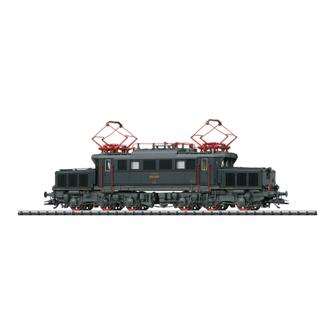
Trix E 50/BR 150 22154 User manual

Modell der E 50 / BR 150
22154

2
Inhaltsverzeichnis:
Seite
Informationen zum Vorbild 4
Sicherheitshinweise 6
Allgemeine Hinweise 6
Funktionen 6
Hinweise zum Digitalbetrieb 7
Schaltbare Funktionen 7
Parameter / Register 8
Betriebshinweise 30
Wartung und Instandhaltung 31
Ersatzteile 38
Table of Contents:
Page
Information about the prototype 4
Safety Notes 9
General Notes 9
Functions 9
Notes on digital operation 10
Controllable Functions 10
Parameter / Register 11
Information about operation 30
Service and maintenance 31
Spare Parts 38
Sommaire :
Page
Informations concernant la locomotive réelle 5
Remarques importantes sur la sécurité 12
Informations générales 12
Fonctionnement 12
Remarques relatives au fonctionnement en mode digital 13
Fonctions commutables 13
Paramètre / Registre 14
Remarques sur l’exploitation 30
Entretien et maintien 31
Pièces de rechange 38
Inhoudsopgave:
Pagina
Informatie van het voorbeeld 5
Veiligheidsvoorschriften 15
Algemene informatie 15
Functies 15
Aanwijzingen voor digitale besturing 16
Schakelbare functies 16
Parameter / Register 17
Opmerkingen over de werking 30
Onderhoud en handhaving 31
Onderdelen 38

3
Indice de contenido:
Página
Aviso de seguridad 18
Informaciones generales 18
Funciones 18
Informaciones para el funcionamiento digital 19
Funciones posibles 19
Parámetro / Registro 20
Instrucciones de uso 30
El mantenimiento 31
Recambios 38
Indice del contenuto:
Pagina
Avvertenze per la sicurezza 21
Avvertenze generali 21
Funzioni 21
Istruzioni per la funzione digitale 22
Funzioni commutabili 22
Parametro / Registro 23
Avvertenze per il funzionamento 30
Manutenzione ed assistere 31
Pezzi di ricambio 38
Innehållsförteckning:
Sida
Säkerhetsanvisningar 24
Allmänna informationer 24
Funktioner 24
Anvisningar för digital drift 25
Kopplingsbara funktioner 25
Parameter / Register 26
Driftanvisningar 30
Underhåll och reparation 31
Reservdelar 38
Indholdsfortegnelse:
Side
Vink om sikkerhed 27
Generelle oplysninger 27
Funktioner 27
Henvisninger til digitaldrift 28
Styrbare funktioner 28
Parameter / Register 29
Brugsanvisninger 30
Service og reparation 31
Reservedele 38

4
Information zum Vorbild:
Im Neubauprogramm der DB wurden für den schweren Gü-
terzugverkehr von Krupp und AEG die sechsachsigen Elekt-
rolokomotiven der BR E 50 entwickelt und gefertigt. Als Basis
diente die Versuchslok E 10 002.
Ab 1957 wurden die Lokomotiven bei der DB in Dienst gestellt.
Bei einer Leistung von 4.500 kW erreichen die 128 t schweren
Loks eine Anfahrzugkraft von 45 t und eine Höchstgeschwin-
digkeit von 100 km/h.
Waren die ersten 25 Loks noch mit Tatzlagerantrieben aus-
gerüstet, wurden alle nachfolgenden mit dem in den E 10 be-
währten Gummiringfederantrieb gebaut. E 50 001 bis E 50 041
hatten 3 große Stirnlampen und waagrechte Lüftungsgitter.
Alle folgenden Loks erhielten 5 kleine Stirnlampen und die
senkrechten Düsenlüftungsgitter.
Bis 1973 wurden 194 Maschinen geliefert. Nachdem die Alt-
bau E-Loks der BR 193 und BR 194 in den 1980er-Jahren aus-
gemustert wurden, übernahmen Loks der BR 150 (so heißen
die E 50 nach der Umstellung seit 1968) den Schiebedienst
auf der Geislinger Steige.
Mitte der 1970er-Jahre wurden viele Elektrolokomotiven der
BR 150 bei Revisionen in oceanblau-beige umlackiert. Ab
1988 wurden die Loks dann in orientrot mit weißem „Lätz-
chen“ und seit 1997 in verkehrsrot mit Querbalken versehen,
zum Teil bei DB Cargo, zum Teil bei Railion.
Information about the Prototype:
Krupp and AEG developed and built the six-axle class E 50
electric locomotives for heavy freight service in the DB‘s new
construction program. The E 10 002 experimental locomotive
served as the basis. These locomotives were placed into
service by the DB starting in 1957. With a performance output
of 4,500 kilowatts or 6,118 horsepower, these 128 metric ton
locomotives have an initial tractive effort of 45 metric tons
and a maximum speed of 100 km/h or 62 mph.
The first 25 units were equipped with axle-suspended trac-
tion motors. The units built after that came with the rubber
ring spring drive traction motors proven in the E 10. Road
numbers E 50 001 to E 50 041 had 3 large headlights and hori-
zontal ventilation grills. All of the locomotives built after these
units had 5 small lights (3 headlights, 2 red marker lights) and
vertical forced air ventilation grills. One hundred ninety four
units had been delivered by 1973. After the older design class
193 and 194 electric locomotives were retired in the Eighties,
the class 150 locomotives (the designation for the E 50 after
the conversion to computer numbering in 1968) were used for
pusher service on the Geislingen Grade.
In the mid-Seventies many of the class 150 electric locomo-
tives were painted in ocean blue / beige when they went in
for overhauls. From 1988 on these locomotives were painted
in Chinese red with white „bibs“ and since 1997 in „traffic
red“ with white horizontal bars, some lettered for DB Cargo,
some lettered for Railion.

5
Informations concernant la locomotive réelle :
Les locomotives électriques à six essieux de la BR E 50
ont été conçues et construites par Krupp et AEG pour le
trafic marchandises lourd dans le cadre du programme de
construction de la DB. La locomotive d’essai E 10 002 servit
de modèle.
Les locomotives furent mises en service par la DB à partir
de 1957. Avec une puissance de 4.500 kW, les locomotives
de 128 t atteignaient un effort au démarrage de 45 t et une
vitesse maximale de 100 km/h.
Si les 25 premières locomotives étaient équipées de moteurs
suspendus par le nez, toutes les suivantes furent dotées
du système de transmission à silent blocs qui avait fait ses
preuves sur les E 10. Les machines E 50 001 à E 50 041 étaient
équipées de trois grands fanaux et de grilles d’aération hori-
zontales. Toutes les locomotives suivantes furent dotées de
5 petits fanaux et des grilles d’aération verticales à effet de
tuyères.
194 machines furent livrées jusqu’en 1973. Après la réforme
des locomotives électriques ancien modèle des séries BR 193
et BR 194 dans les années 1980, les locomotives de la série BR
150 (nouvelle immatriculation des E 50 dans le nouveau sys-
tème de 1968) assurèrent le service de pousse sur la rampe de
Geislingen («Geislinger Steige»).
Au milieu des années 70, de nombreuses locomotives élec-
triques de la série 150 furent dotées lors de révisions d’une nou-
velle livrée bleu océan-beige. A partir de 1988, les locomotives
passèrent alors au rouge orient avec une «bavette» blanche et,
depuis 1997, au rouge trafic avec bandes transversales, en par-
tie à la DB Cargo, en partie à la Railion.
Informatie van het voorbeeld:
Binnen het nieuwbouwprogramma van de DB werden voor
het zware goederentreinverkeer door Krupp en AEG de zes-
assige elektrische locomotieven van de serie E 50 ontwik-
keld en gebouwd. Als basis diende de testloc E 10 002.
Vanaf 1957 werden de locomotieven bij de DB in dienst ge-
nomen. Bij een vermogen van 4.500 kW bereikten de 128 t
zware locomotieven een aanzettrekkracht van 45 t en een
maximumsnelheid van 100 km/h.
Terwijl de eerste 25 locs nog met klauwlager-aandrijving
waren uitgerust, werden alle daarop volgende machines
voorzien van een rubberring-veeraandrijving die zich bewe-
zen had bij de serie E 10. De E 50 001 t/m de E 50 041 had-
den drie grote frontseinen en horizontale ventilatieroosters.
Alle volgende locs kregen 5 kleine frontseinen en verticaal
geplaatste ventilatieroosters.
Tot 1973 werden 194 machines geleverd. Nadat de oudere
typen van de serie 193 en 194 in de jaren tachtig buiten dienst
werden genomen, namen de locs van de serie 150 (zo heten
de E 50 locs na de omnummering sinds 1968) de opduwdienst
op de “Geislinger Steige”.
In het midden van de zeventiger-jaren werden veel E-locs
van de serie 150, bij een grote revisie, overgeschilderd in
oceaanblauw/beige. Vanaf 1988 werden de locs oriëntrood
met een wit “slabbetje” en sinds 1997 verschenen ze in ver-
keersrood met een witte balk, voor een deel bij DB Cargo en
een deel bij Railion.
6
Sicherheitshinweise
• DieLokdarfnurmiteinemdafürbestimmtenBetriebssys-
tem eingesetzt werden.
• NurSchaltnetzteileundTransformatorenverwenden,die
Ihrer örtlichen Netzspannung entsprechen.
• DieLokdarfnurauseinerLeistungsquelleversorgtwerden.
• BeachtenSieunbedingtdieSicherheitshinweiseinder
Bedienungsanleitung zu Ihrem Betriebssystem.
•FürdenkonventionellenBetriebderLokmussdas
Anschlussgleis entstört werden. Dazu ist das Entstörset
611 655 zu verwenden. Für Digitalbetrieb ist das Entstörset
nicht geeignet.
• ACHTUNG! Funktionsbedingte scharfe Kanten und Spitzen.
•SetzenSiedasModellkeinerdirektenSonneneinstrah-
lung, starken Temperaturschwankungen oder hoher
Luftfeuchtigkeit aus.
Allgemeine Hinweise
•DieBedienungsanleitungunddieVerpackungsindBe-
standteil des Produktes und müssen deshalb aufbewahrt
sowie bei Weitergabe des Produktes mitgegeben werden.
•FürReparaturenoderErsatzteilewendenSiesichbittean
Ihren Trix-Fachhändler.
•http://www.maerklin.com/en/imprint.html
Funktionen
• EingebauteElektronikzumwahlweisenBetriebmitkon-
ventionellem Gleichstrom-Fahrgerät (max. ±12 Volt),
Trix Systems oder Digitalsystemen nach NMRA-Norm.
• AutomatischeSystemerkennungzwischenDigital-und
Analog-Betrieb.
•DervolleFunktionsumfangistnurunterTrixSystemsund
unter DCC verfügbar.
• Eingebaute,fahrtrichtungsabhängigeStirnbeleuchtung.
Im Digitalbetrieb schaltbar.
•BefahrbarerMindestradius360mm.
Jegliche Garantie-, Gewährleistungs- und Schadensersatzansprüche
sind ausgeschlossen, wenn in Trix-Produkten nicht von Trix freigegebene
Fremdteile eingebaut werden und / oder Trix-Produkte umgebaut werden
und die eingebauten Fremdteile bzw. der Umbau für sodann aufgetretene
Mängel und / oder Schäden ursächlich war. Die Darlegungs- und Beweis-
last dafür, dass der Einbau von Fremdteilen oder der Umbau in bzw. von
Trix-Produkten für aufgetretene Mängel und/oder Schäden nicht ursächlich
war, trägt die für den Ein- und / oder Umbau verantwortliche Person und/
oder Firma bzw. der Kunde.

7
Schaltbare Funktionen
Stirnbeleuchtung an Funktion f0 Funktion f0
Licht am Führerstand 1 aus — Funktion 1 Funktion f1 Funktion f1
Licht am Führerstand 2 aus — Funktion 2 Funktion f2 Funktion f2
Telexkupplung — Funktion 3 Funktion f3 Funktion f3
ABV — Funktion 4 Funktion f4 Funktion f4
Geräusch:Pfeife — Funktion 5 Funktion f5 Funktion f5
Rangierlicht Doppel-A — + 1 + 2 Funktion f0 + f1 + f2 Funktion f0 + f1 + f2
STOP mobile station
15
f0 f8 f0f8
f0 - f3 f4 - f7
Hinweise zum Digitalbetrieb
• DiegenaueVorgehensweisezumEinstellenderdiversen
Parameter entnehmen Sie bitte der Bedienungsanleitung
Ihrer Mehrzug-Zentrale.
•DieabWerkeingestelltenWertesindsogewählt,dass
bestmöglichstes Fahrverhalten gewährleistet ist.
• DerBetriebmitgegenpoligerGleichspannungim
Bremsabschnitt ist mit der werkseitigen Einstellung nicht
möglich. Ist diese Eigenschaft gewünscht, so muss auf
den konventionellen Gleichstrombetrieb verzichtet werden
(CV 29 / Bit 2 = 0).

8
CV Bedeutung Wert DCC ab Werk
1 Adresse 1 - 127 3
2 PoM Minimalgeschwindigkeit 0 - 255 8
3 PoM Anfahrverzögerung 0 - 255 5
4 PoM Bremsverzögerung 0 - 255 6
5 PoM Maximalgeschwindigkeit 0 - 255 195
8 Werkreset/Herstellerkennung 8 131
13 PoM Funktionen F1 - F8 im Analogbetrieb 0 - 255 0
14 PoM Funktionen F9 - F15 und Licht im Analogbetrieb 0 - 255 1
17 Erweiterte Adresse (oberer Teil) CV 29, Bit 5 =1 192
18 Erweiterte Adresse (unterer Teil) CV 29, Bit 5 =1 128
19 Traktionsadresse 0 - 255 0
21 PoM Funktionen F1 - F8 bei Traktion 0 - 255 0
22 PoM Funktionen F9 - F15 und Licht bei Traktion 0 - 255 0
29
Bit0:UmpolungFahrtrichtung
Bit1:AnzahlFahrstufen14oder28/128
Bit2:DCCBetriebmitBremsstrecke(keinAnalogbetriebmöglich)
Bit5:Adressumfang7Bit/14Bit
0 / 1
0 / 2
0 / 4
0 / 32
6*
PoM = Program on the Main; muss vom Steuergerät unterstützt werden
* Die Werte der gewünschten Einstellungen sind zu addieren!

9
Functions
• Built-inelectroniccircuitforoperationwithaconventional
DC power pack (max. ±12 volts), Trix Systems or NMRA
DCC digital systems.
• Automaticsystemrecognitionbetweendigitalandanalog
operation.
•ThefullrangeoffunctionsisonlyavailableunderTrix
Systems and under DCC.
• Built-inheadlightsthatchangeoverwiththedirectionof
travel. They can be turned on and off in digital operation.
•Minimumradiusforoperationis360mm/14-3/16“.
No warranty or damage claims shall be accepted in those cases where
parts neither manufactured nor approved by Trix have been installed in
Trix products or where Trix products have been converted in such a way
that the non-Trix parts or the conversion were causal to the defects and /
or damage arising. The burden of presenting evidence and the burden of
proof thereof, that the installation of non-Trix parts or the conversion in or
of Trix products was not causal to the defects and / or damage arising, is
borne by the person and/or company responsible for the installation and /
or conversion, or by the customer.
Safety Notes
• Thislocomotiveisonlytobeusedwiththeoperating
system it is designed for.
• Useonlyswitchedmodepowersupplyunitsandtransfor-
mers that are designed for your local power system.
• Thislocomotivemustnotbesuppliedwithpowerfrom
more than one power pack.
• Pleasemakenoteofthesafetynotesintheinstructionsfor
your operating system.
•Thefeedertrackmustbeequippedtopreventinterference
with radio and television reception, when the locomotive
is to be run in conventional operation. The 611 655 inter-
ference suppression set is to be used for this purpose.
The interference suppression set is not suitable for digital
operation.
• WARNING! Sharp edges and points required for operation.
•Donotexposethemodeltodirectsunlight,extremechan-
ges in temperature, or high humidity.
General Notes
•Theoperatinginstructionsandthepackagingareacom-
ponent part of the product and must therefore be kept as
well as transferred along with the product to others.
•PleaseseeyourauthorizedTrixdealerforrepairsorspare
parts.
•http://www.maerklin.com/en/imprint.html

10
Controllable Functions
Headlights on Function f0 Function f0
Headlights at engineer´s cab 1 off — Function 1 Function f1 Function f1
Headlights at engineer´s cab 2 off — Function 2 Function f2 Function f2
Telex coupler — Function 3 Function f3 Function f3
ABV — Function 4 Function f4 Function f4
Soundeffect:Locomotivewhistle — Function 5 Function f5 Function f5
Double A switching light — + 1 + 2 Function f0 + f1 + f2 Function f0 + f1 + f2
STOP mobile station
15
f0 f8 f0f8
f0 - f3 f4 - f7
Notes on digital operation
•Theoperatinginstructionsforyourcentralunitwillgive
you exact procedures for setting the different parameters.
• Thevaluessetatthefactorywereselectedtoguarantee
the best possible running characteristics.
• Thesettingdoneatthefactorydoesnotpermitoperation
with opposite polarity DC power in the braking block. If
you want this characteristic, you must do without conven-
tional DC power operation (CV 29 / Bit 2 = 0).

11
PoM = Program on the Main; must be supported by the controller
* The values for the desired settings must be added.
CV Discription DCC Value Factory-Set
1 Adresse 1 - 127 3
2 PoM Minimum Speed 0 - 255 8
3 PoM Acceleration delay 0 - 255 5
4 PoM Braking delay 0 - 255 6
5 PoM Maximum speed 0 - 255 195
8 Factory Reset / Manufacturer Recognition 8 131
13 PoM Functions F1 - F8 in analog operation 0 - 255 0
14 PoM Functions F9 - F15 and lights in analog operation 0 - 255 1
17 Extended address (upper part) CV 29, Bit 5 =1 192
18 Extended address (lower part) CV 29, Bit 5 =1 128
19 Multiple Unit Address 0 - 255 0
21 PoM Functions F1 - F8 on Multiple Unit 0 - 255 0
22 PoM Functions F9 - F15 and lights on Multiple Unit 0 - 255 0
29
Bit0:Reversingdirection
Bit1:Numberofspeedlevels14or28/128
Bit2:DCCoperationwithbrakingarea(noanalogoperationpossible)
Bit5:Addresslength7Bit/14Bit
0 / 1
0 / 2
0 / 4
0 / 32
6*

12
Remarques importantes sur la sécurité
• Lalocomotivenepeutêtreutiliséequ‘aveclesystème
d‘exploitation indiqué.
• Utiliseruniquementdesconvertisseursettransformateurs
correspondant à la tension du secteur local.
• Lalocomotivenepeutpasêtrealimentéeélectriquement
par plus d‘une source de courant à la fois.
• Ilestimpératifdetenircomptedesremarquessurla
sécurité décrites dans le mode d‘emploi de votre système
d‘exploitation.
•
Pour l’exploitation de la locomotive en mode convention-
nel,lavoiederaccordementdoitêtredéparasitée.Acet
effet, utiliser le set de déparasitage réf. 611 655. Le set de
déparasitage ne convient pas pour l’exploitation en mode
numérique.
•
ATTENTION! Pointes et bords coupants lors du fonctionne-
ment du produit.
•Nepasexposerlemodèleàunensoleillementdirect,àde
fortes variations de température ou à un taux d‘humidité
important.
Informations générales
•Lanoticed‘utilisationetl’emballagefontpartieintégrante
duproduit;ilsdoiventdoncêtreconservéset,lecas
échéant, transmis avec le produit.
•Pourtouteréparationouremplacementdepièces,adres-
sez vous à votre détaillant-spécialiste Trix.
•http://www.maerklin.com/en/imprint.html
Fonctionnement
• Electroniqueintégréepourexploitationauchoixavectrans-
formateur-régulateur conventionnel délivrant du courant con-
tinu (max. ±12 volts), avec Trix Systems ou avec des systèmes
de conduite digitale conformes aux normes NMRA.
• Reconnaissanceautomatiquedusystèmeentreexploitati-
ons numérique et analogique.
•L’intégralitédesfonctionsestdisponibleuniquementen
exploitation Trix Systems et DCC.
• Feuxdesignalisations‘inversantselonlesensdemarche;
feux commutables en exploitation digital.
•Rayonminimald’inscriptionencourbe360mm.
Tout recours à une garantie commerciale ou contractuelle ou à une demande
dedommages-intérêtestexclusidespiècesnonautoriséesparTrixsont
intégrées dans les produits Trix et / ou si les produits Trix sont transformés et
si les pièces d’autres fabricants montées ou la transformation constituent la
cause des défauts et/ou dommages apparus. C’est à la personne et / ou la so-
ciété responsable du montage / de la transformation ou au client qu’incombe
la charge de prouver que le montage des pièces d’autres fabricants sur des
produits Trix ou la transformation des produits Trix n’est pas à l’origine des
défauts et ou dommages apparus.

13
Fonctions commutables
Fanal Activé Fonction f0 Fonction f0
Fanal de la cabine de conduite 1 éteint — Fonction 1 Fonction f1 Fonction f1
Fanal de la cabine de conduite 2 éteint — Fonction 2 Fonction f2 Fonction f2
Attelage Telex — Fonction 3 Fonction f3 Fonction f3
ABV — Fonction 4 Fonction f4 Fonction f4
Bruitage:Sifetlocomotive — Fonction 5 Fonction f5 Fonction f5
Feu de manœuvre double A — + 1 + 2 Fonction f0 + f1 + f2 Fonction f0 + f1 + f2
STOP mobile station
15
f0 f8 f0f8
f0 - f3 f4 - f7
Remarques relatives au fonctionnement en mode digital
•Encequiconcernelaprocédurederéglagedesdiverspa-
ramètres, veuillez vous référer au mode d‘emploi de votre
centrale de commande multitrain.
•Lesvaleursparamétréesd’usinesontchoisiesdemanièreà
garantir le meilleur comportement de roulement possible.
• L’exploitationaveccourantcontinudepolaritéinverse
dans les sections de freinage n’est pas possible avec le
réglage d’usine. Si cette propriété est désirée, il faut alors
renoncer à l’exploitation conventionnelle en courant conti-
nu (CV 29 / Bit 2 = 0).

14
PoM=ProgramontheMain;doitêtreprisenchargeparl’appareildecommande
* Les valeurs des réglages désirés sont à additioner.
CV Affectation DCC Valeur Parm. Usine
1 Adresse 1 - 127 3
2 PoM Vitesse minimale 0 - 255 8
3 PoM Temporisation d‘accélération 0 - 255 5
4 PoM Temporisation de freinage 0 - 255 6
5 PoM Vitesse maximale 0 - 255 195
8 Réinitialisation d’usine/identification du fabricant 8 131
13 PoM Fonctions F1 - F8 en mode analog 0 - 255 0
14 PoM Fonctions F9 - F15 et éclairage en mode analog 0 - 255 1
17 Adresse étendue (partie supérieure) CV 29, Bit 5 =1 192
18 Adresse étendue (partie inférieure) CV 29, Bit 5 =1 128
19 Adresse traction 0 - 255 0
21 PoM Fonctions F1 - F8 pour traction 0 - 255 0
22 PoM Fonctions F9 - F15 et éclairage traction 0 - 255 0
29
Bit0:Inv.polaritéSensdemarche
Bit1:Nombredecransdemarche14ou28/128
Bit2:
Mode DCC avec dist. de freinage (mode analog impossible)
Bit5:Capacitéd’adresses7Bit/14Bit
0 / 1
0 / 2
0 / 4
0 / 32
6*

15
Veiligheidsvoorschriften
• Delocmagalleenmeteendaarvoorbestemdbedrijfssys-
teem gebruikt worden.
• Alleennet-adaptersentransformatorengebruikenwaarvan
de aangegeven netspanning overeenkomt met de netspan-
ning ter plaatse.
• Delocmagnietvanuitmeerdanéénstroomvoorziening
gelijktijdig gevoed worden.
• Leesookaandachtigdeveiligheidsvoorschrifteninde
gebruiksaanwijzing van uw bedrijfssysteem.
•Voorhetconventionelebedrijfmetdelocdientde
aansluitrail te worden ontstoort. Hiervoor dient men de
ontstoor-set 611 655 te gebruiken. Voor het digitale bedrijf
is deze ontstoor-set niet geschikt.
• OPGEPAST! Functionele scherpe kanten en punten.
•Stelhetmodelnietblootaanindirectezonnestraling,
sterke temperatuurwisselingen of hoge luchtvochtigheid.
Algemene informatie
•Degebruiksaanwijzingendeverpakkingzijneenbestand-
deel van het product en dienen derhalve bewaard en
meegeleverd te worden bij het doorgeven van het product.
•VoorreparatiesenonderdelenkuntzichtotuwTrixhande-
laar wenden.
•http://www.maerklin.com/en/imprint.html
Functies
• Ingebouwdeelektronicadiehetmogelijkmaaktomnaar
keuze met, een conventionele gelijkstroomrijregelaar
(max. ±12 Volt), Trix Systems of digitaalsysteem volgens
NMRA-norm te rijden.
• Automatischesysteemherkenningtussendigitaal-en
analoogbedrijf.
•Devolledigetoegangtotallefunctiesisalleenmogelijk
met Trix Systems of met DCC bedrijf.
• Ingebouwde,rijrichtingsafhankelijkefrontverlichting.
•Minimaleteberijdenradius:360mm.
Elke aanspraak op garantie en schadevergoeding is uitgesloten, wanneer in
Trix-producten niet door Trix vrijgegeven vreemde onderdelen ingebouwd
en / of Trix-producten omgebouwd worden en de ingebouwde vreemde
onderdelen resp. de ombouw oorzaak van nadien opgetreden defecten
en / of schade was. De aantoonplicht en de bewijslijst daaromtrent, dat
de inbouw van vreemde onderdelen in Trix-producten of de ombouw van
Trix-producten niet de oorzaak van opgetreden defecten en / of schade is
geweest, berust bij de voor de inbouw en / of ombouw verantwoordelijke
persoon en / of firma danwel bij de klant.

16
Schakelbare functies
Frontverlichting aan Functie f0 Functie f0
Frontverlichting Cabine 1 uit — Functie 1 Functie f1 Functie f1
Frontverlichting Cabine 2 uit — Functie 2 Functie f2 Functie f2
Telex-koppeling — Functie 3 Functie f3 Functie f3
ABV — Functie 4 Functie f4 Functie f4
Geluid:locuit — Functie 5 Functie f5 Functie f5
Rangeerlicht dubbel A — + 1 + 2 Functie f0 + f1 + f2 Functie f0 + f1 + f2
STOP mobile station
15
f0 f8 f0f8
f0 - f3 f4 - f7
Aanwijzingen voor digitale besturing
•Hetopdejuistewijzeinstellenvandediverseparame-
ters staat beschreven in de handleiding van uw digitale
Centrale.
•Devanafdefabriekingesteldewaardenzijnzoingesteld
dat de rij-eigenschappen optimaal zijn.
• Hetbedrijfmettegengepooldegelijkspanningindeafrem-
sectie is met de fabrieksinstelling niet mogelijk. Indien deze
eigenschap wenselijk is, dan moet worden afgezien van het
conventioneel gelijkstroombedrijf (CV 29 / Bit 2 = 0).

17
PoM = Program on the Main; dient door het besturingsapparaat ondersteunt te worden.
* De waarde van de gewenste instellingen moeten bij elkaar opgeteld worden.
CV Betekenis Waarde DCC Af fabriek
1 Adres 1 - 127 3
2 PoM Minimale snelheid 0 - 255 8
3 PoM Optrekvertraging 0 - 255 5
4 PoM Afremvertraging 0 - 255 6
5 PoM Maximumsnelheid 0 - 255 195
8 Fabrieksinstelling/fabriekherkenning 8 131
13 PoM functies F1 - F8 in analoogbedrijf 0 - 255 0
14 PoM functies F9 - F15 en licht in analoogbedrijf 0 - 255 1
17 Uitgebreld adres (bovenste gedeelte) CV 29, Bit 5 =1 192
18 Uitgebreld adres (onderste gedeelte) CV 29, Bit 5 =1 128
19 tractieadres 0 - 255 0
21 PoM functies F1 - F8 in tractie 0 - 255 0
22 PoM functies F9 - F15 en licht in tractie 0 - 255 0
29
Bit0:ompolenrijrichting
Bit1:aantalrijstappen14of28/128
Bit2:DCCbedrijfmetafremtraject(geenanaloogbedrijfmogelijk)
Bit5:adresomvang7Bit/14Bit
0 / 1
0 / 2
0 / 4
0 / 32
6*

18
Aviso de seguridad
• Lalocomotorasolamentedebefuncionarenelsistema
que le corresponda.
• Emplearúnicamentefuentesdealimentaciónconmutadas
ytransformadoresqueseandelatensiónderedlocal.
• Lalocomotoranodeberárecibircorrientemásquedeun
solo punto de abasto a la vez.
• Observenecesariamentelosavisosdeseguridadindica-
dos en las instrucciones correspondientes a su sistema de
funcionamiento.
•Paraelfuncionamientoconvencionaldelalocomotorade-
bensuprimirselasinterferenciasenlavíadeconexiónde
laalimentación.Paraellodebeemplearseelsetsupresor
de interferencias 611 655.
• ¡ATENCIÓN! Esquinas y puntas afiladas condicionadas a
lafunción.
•Noexponerelmodeloenminiaturaalaradiaciónsolar
directa, a oscilaciones fuertes de temperatura o a una
humedad del aire elevada.
Informaciones generales
•Lasinstruccionesdeempleoyelembalajeformanparte
íntegra del producto y, por este motivo, deben guardarse y
entregarse junto con el producto en el caso de venderlo o
transmitirlo a otro.
•Encasodeprecisarunareparaciónopiezasderecambio,
rogamos ponerse en contacto con su distribuidor Trix.
•http://www.maerklin.com/en/imprint.html
Funciones
• Electrónicaincorporadaparaunfuncionamientoadiscre-
ciónencorrientecontinuaconvencional(máx.±12V.),Trix
SystemsosistemasDigitalsegúnlasnormasNMRA.
• Detecciónautomáticadelsistemaentrelosmodosdigital
yanalógico.
• Laplenafuncionalidaddefuncionesestádisponiblesólo
en Trix Systems y en DCC.
• Losfarosfrontalesdependendelsentidodelamarcha.
En Digital se pueden encender y apagar.
•Radiomínimodescribible360mm.
Seexcluyetododerechodegarantía,prestacióndegarantíaeindemnización
sobre aquellos productos Trix en los que se hubieran montado piezas ajenas no
autorizadas por Trix y/o sobre aquellos productos Trix que hayan sido modifica-
doscuandolapiezasajenasmontadasolamodicaciónseanlascausasdelos
desperfectos y/o daños posteriormente surgidos. La persona y/o empresa o el
clienteresponsabledelmontajeomodicaciónseráelresponsabledeprobar
yalegarqueelmontajedepiezasajenasolamodicaciónen/deproductosTrix
no son las causas de los desperfectos y/o daños surgidos.

19
Funciones posibles
Faros frontales encendido Funciónf0 Funciónf0
Faros frontales a la cabina 1 de enganche — Función1 Funciónf1 Funciónf1
Faros frontales a la cabina 2 de enganche — Función2 Funciónf2 Funciónf2
Enganche Telex — Función3 Funciónf3 Funciónf3
ABV — Función4 Funciónf4 Funciónf4
Ruido del silbido — Función5 Funciónf5 Funciónf5
Luces de maniobra doble A — + 1 + 2 Funciónf0+f1+f2 Funciónf0+f1+f2
STOP mobile station
15
f0 f8 f0f8
f0 - f3 f4 - f7
Informaciones para el funcionamiento digital
• Deberáconsultarelprocedimientoexactodeconguraci-
óndelosdiversosparámetrosenelmanualdeinstruc-
ciones de la central multitren que desee utilizar.
• Losvaloresconguradosenfábricasehanelegidode
modo que queden garantizadas las mejores característi-
casdeconducciónposibles.
• Noesposibleelfuncionamientocontensióndecorriente
continua de polaridad opuesta en el tramo de frenado en
funcionamiento en modo DCC. Si se desea esta caracterí-
stica, debe renunciarse al funcionamiento convencional
con corriente continua (CV 29 / Bit 2 = 0).

20
PoM = Program on the Main; debe ser soportado por la unidad de control
* ¡Los valores de los ajustes deseados deben sumarse!
CV Significado Valor DCC Preselección
1Códigos 1 - 127 3
2 PoM Velocidad mínima 0 - 255 8
3 PoM Arranque progresivo 0 - 255 5
4 PoM Frenado progresivo 0 - 255 6
5 PoM Velocidad máxima 0 - 255 195
8Resetdefábrica/códigodefabricante 8 131
13 PoM FuncionesF1-F8enelmodoanalógico 0 - 255 0
14 PoM FuncionesF9-F15ylucesenelmodoanalógico 0 - 255 1
17 Direcciónampliada(partesuperior) CV 29, Bit 5 =1 192
18 Direcciónampliada(parteinferior) CV 29, Bit 5 =1 128
19 Direccióndetracción 0 - 255 0
21 PoM FuncionesF1-F8entracción 0 - 255 0
22 PoM FuncionesF9-F15ylucesentracción 0 - 255 0
29
Bit0:Cambiodepolaridaddelsentidodemarcha
Bit1:Númerodenivelesdemarcha14ó28/128
Bit2:ModoDCCcontrayectodefrenado(noesposibleelmodoanalógico)
Bit5:Tamañodedirecciones7Bits/14Bits
0 / 1
0 / 2
0 / 4
0 / 32
6*
Table of contents
Languages:
Other Trix Toy manuals

Trix
Trix MINITRIX 16662 User manual

Trix
Trix VT 11.5 Series User manual

Trix
Trix Minitrix 66540 User manual

Trix
Trix BR 420 User manual

Trix
Trix BR 08 User manual

Trix
Trix 602 Series User manual

Trix
Trix BR 44 Marklineum User manual

Trix
Trix G 1205 User manual

Trix
Trix H0 CidT User manual

Trix
Trix BR 73 0-1 User manual

Trix
Trix H0 Kof III User manual

Trix
Trix Class 45 User manual

Trix
Trix Litra E 991 User manual

Trix
Trix 22605 User manual

Trix
Trix Henschel User manual

Trix
Trix 1100 Series User manual

Trix
Trix Re 14 Green Cargo User manual

Trix
Trix 25810 User manual

Trix
Trix BR 798 User manual

Trix
Trix Triebzuges ET 87 User manual