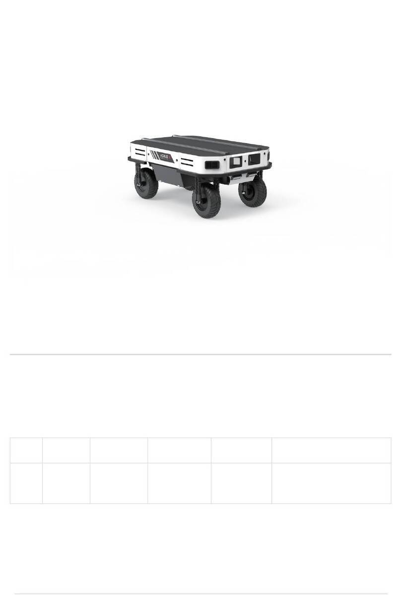
AgileX BUNKER User manual

AgileX Robotics Team
BUNKER
User Manual 2020.08V.2.0.0

This chapter contains important safety information, before the robot is powered on for the first time, any
individual or organization must read and understand this information before using the device. If you have
assembly instructions and guidelines in the chapters of this manual, which is very important. Particular
attention should be paid to the text related to the warning signs.

Make a risk assessment of the complete robot system.
Connect the additional safety equipment of other machinery
defined by the risk assessment together.
Confirm that the design and installation of the entire robot
system's peripheral equipment, including software and
hardware systems, are correct.
This robot does not have a complete autonomous mobile robot,
including but not limited to automatic anti-collision, anti-falling,
biological approach warning and other related safety functions.
Related functions require integrators and end customers to
follow relevant regulations and feasible laws and regulations for
safety assessment , To ensure that the developed robot does not
have any major hazards and safety hazards in actual
applications.
Collect all the documents in the technical file: including risk
assessment and this manual.
Know the possible safety risks before operating and using the
equipment.
Safety Information
1.Effectiveness and responsibility 2.Environmental Considerations
3.Pre-work Checklist
The information in this manual does not include the design, installation and operation of a complete robot application, nor does it include all
peripheral equipment that may affect the safety of the complete system. The design and use of the complete system need to comply with the
safety requirements established in the standards and regulations of the country where the robot is installed. BUNKER integrators and end
customers have the responsibility to ensure compliance with the applicable laws and regulations of relevant countries, and to ensure that there
are no major dangers in the complete robot application. This includes but is not limited to the following:
For the first use,please read this manual carefully to
understand the basic operating content and operating
specification.
For remote control operation, select a relatively open area
to use Bunker, because Bunker is not equipped with any
automatic obstacle avoidance sensor.
Use Bunker always under -20℃~60℃ ambient temperature.
If Bunker is not configured with separate custom IP
protection, its water and dust protection will be IP44 ONLY.
Make sure each device has sufficient power.
Make sure Bunker does not have any obvious defects.
Check if the remote controller battery has sufficient
power.
When using, make sure the emergency stop switch
has been released.
!
5.Maintenance
4.Operation
When BUNKER has had a defect, please contact the
relevant technical to deal with it, do not handle the
defect by yourself.
Always use BUNKER in the environment with the
protection level requires for the equipment.
Do not push BUNKER directly.
When charging, make sure the ambient temperature is
above 0℃.
In remote control operation, make sure the area around is
relatively spacious.
Carry out remote control within the range of visibility.
The maximum load of BUNKER is 70KG. When in use, ensure that
the payload does not exceed 70KG.
When installing an external extension on BUNKER, confirm the
position of the center of mass of the extension and make sure it is
at the center of rotation.
Please charge in time when the device voltage is lower than 48V.
When BUNKER has a defect, please immediately stop using it to
avoid secondary damage.
Regularly check the tension of the hanging crawler, and tighten the crawler every 150~200h.
After every 500 hours of operation, the bolts and nuts of each part of the car body should be inspected. If they are loose, they must be
tightened immediately.
In order to ensure the storage capacity of the battery, the battery should be stored under electricity, and it should be charged regularly
when not used for a long time.
1 Bunker Introduction
1.1 Component list
1.2 Tech specifications
1.3 Required for development
2 The Basics
2.1 Description of electrical
interface
2.2 Instruction on remote control
2.3 Instruction on control
demands and movements
3 Getting Started
3.1 Use and operation
3.2 Charging
3.3 Communication using CAN
3.3.2 CAN Cable Connection
3.3.3 Implementation of CAN
command control
3.4 Firmware upgrades
4 Attention
4.1 Battery
4.2 Operational environment
4.3 Electrical /extension cords
4.4 Additional safety advice
4.5 Other notes
5 Q&A
6 Product Dimensions
6.1 Product outline dimension
illustration
6.2 Top expansion stent size
description diagram
1
1
1
1
2
2
2
3
4
4
4
4
8
8
8
9
9
9
9
9
9
10
11
11
12
CONTENTS

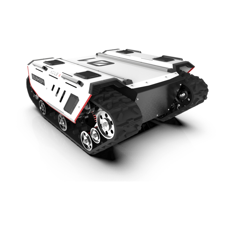
BUNKER is designed as a multi-purpose tracked chassis with different application scenarios considered: simple and sensitive
operation, large development space, adapt to various fields of development and application, independent suspension system,
high payload and suspension, strong climbing ability, can climb stairs. It can be used for the development of special robots such
as inspection and exploration, rescue and detonation, special shooting, special transportation, etc., to solve the robot mobile
solution.
FS RC transmitter is provided (optional) in the factory setting of BUNKER, which allows users to control the chassis of robot to
move and turn; CAN and RS232 interfaces on BUNKER can be used for user’s customization.
1 BUNKER Introduction
1.1 Component list
1.2 Tech specifications
1.3 Required for development
BUNKER Robot Body
Battery Charger(AC 220V)
Aviation plug(4Pin)
USB to RS232
USB to CAN communication module
FS remote control transmitter(Optional)
x1
x1
x2
x1
x1
x1
Name Quantity
Parameter Types Items Values
Dimensions
Battery
Motion
Control
Weight
Dimensions
Inner dimensions
Chassis height
Track width
Length
Weight
Load
Type
Capacity
Voltage
Maximum climbing capacity
Speed
Minimum turning radius
Maximum obstacle
Control mode
RC transmitter
Communication interface
1023*780*394mm
600*300*230mm
90mm
150mm
520mm
About 130kg
80kg
Lithium battery
30AH
48V
36°
0~1.5m/s
Be able to turn on a pivot
170mm
Remote control
2.4G/extreme distance 1KM
CAN
1

This section provides a brief introduction to the BUNKER mobile robot platform. It is convenient for users and developers to
have a basic understanding of BUNKER chassis.
The interface at rear end is shown in Figure 2-1, where Q1 is CAN and 48V power supply aviation interface; Q2 is the power switch;
Q3 is the recharging interface; Q4 is the aerial; Q5 is the drive test interface; Q6 is the emergency stop switch; Q7 is the display of
battery voltage.
FS RC transmitter is an optional accessory of BUNKER for
manually controlling the robot. The transmitter comes with
a left-hand-throttle configuration. The functions of the
buttons are defined as: SWA, SWC, SWD are enabled by
default. SWB for control mode selection, top position for
command control mode and the middle position for remote
control mode. When configuring the autowalker navigation
system, the bottom is the navigation control mode. S1 is the
throttle button to control the forward and backward of
BUNKER; S2 controls the rotation, POWER is the power
button, and it can be turned on at the same time. It should
be noted that when the remote controller is turned on, SWA,
SWB, SWC, SWD all need to be at the top.
2 The Basics
2.1Description of electrical interface
2.2Instructions on remote control
Figure 2.1 Tail electrical interface
The definitions of Q1 communication and power interface as shown in Figure 2-2.
Figure 2.2 Pin definition figure of
tail aviation expansion interface
1
2
3
4
Power
CAN
Power
CAN
VCC
GND
CAN_H
CAN_L
Power positive, voltage range
46 - 54V, maximum current 10A
Power negative
CAN bus high
CAN bus low
Pin No. Pin Type Function and
Defition Remarks
2
1
4
3
Figure 2.3 Schematic Diagram of Buttons on
FS RC transmitter
SWC
SWD
S2
SWB
SWA
S1
POWER
POWER
2
Q7
Q4
Q1
Q2 Q6 Q5
Q3

A reference coordinate system can be defined and fixed on the vehicle body as shown in Figure 2.4 in accordance with ISO 8855.
As shown in Figure 2.4, the vehicle body of BUNKER is in parallel with X axis of the established reference coordinate system.
In RC control mode, push the remote control stick S1 forward to move in the positive X direction, push stick S1 backward to
move in the negative X direction. When S1 is pushed to the maximum value, the movement speed in the positive X direction is
the maximum, when S1 is pushed to the minimum value, the movement speed is the maximum in the negative direction of the
X direction.The remote control stick S2 controls the rotation of the car body left and right. The remote control joystick S2
controls the rotation of the car body left and right. When S2 pushes the car body to the left, it rotates from the positive direction
of the X axis to the positive direction of the Y axis. When S2 pushes the car body to the right, it rotates from the positive direction
of the X axis to the negative direction of the Y axis. S2 When pushing to the left to the maximum value, the counterclockwise
rotation speed is the maximum. When S2 is pushed to the right to the maximum value, the clockwise rotation speed is the
maximum.
Following this convention, a positive linear velocity corresponds to the forward movement of the vehicle along positive x-axis
direction and a positive angular velocity corresponds to positive right-hand rotation about the z-axis.
2.3Instructions on control demands and movements
Figure 2.4 Schematic Diagram of Reference
Coordinate System for Vehicle Body
Z
X
Y
3

This section introduces the basic operation and development of the BUNKER platform using the CAN bus interface.
BUNKER provides CAN interfaces for user customization. Users can to conduct command control over the vehicle body by this
interface.
BUNKER adopts CAN2.0B communication standard which has a communication baud rate of 500K and Motorola message format.
Via external CAN bus interface, the moving linear speed and the rotational angular speed of chassis can be controlled; BUNKER will
feedback on the current movement status information and its chassis status information in real time.
The protocol includes system status feedback frame, movement control feedback frame and control frame, the contents of which
are shown as follows:
The system status feedback command includes the feedback information about current status of vehicle body, control mode status,
battery voltage and system failure. The description is given in Table 3.1.
BUNKER is equipped with a standard charger by default to meet customers' recharging demand.
3 Getting Started
3.1 Use and operation
3.2 Charging
3.3 Communication using CAN
Check the condition of vehicle body. Check whether there
are significant anomalies; if so, please contact the after-sale
service personnel for support;
Check the state of emergency stop switches. Make sure Q6
emergency stop button at the rear is released;
For first-time use, check whether Q3 (drive power supply
switch) on the rear panel has been pressed down; if so,
please release it, and then the drive will be powered off;
Make sure the electricity of BUNKER chassis is powered off. Before charging, please make sure Q2 (key switch) in the rear
control console is turned off;
Insert the charger plug into Q3 charging interface on the rear control panel;
Connect the charger to power supply and turn on the switch in the charger. Then, the robot enters the charging state.
After the chassis of BUNKER mobile robot is started correctly, turn on the RC transmitter and select the remote-control mode.
Then, BUNKER platform movement can be controlled by the RC transmitter.
Press the key switch to cut off the power supply; Press down emergency push button at the rear of BUNKER
vehicle body;
Press the key switch (Q2 on the electrical panel), and
normally, the voltmeter will display correct battery voltage
and front and rear lights will be both switched on;
Check the battery voltage. If the voltage is higher than 48V,
it means the battery voltage is correct; if the battery power
level is low, please charge the battery;
Check Startup
Shutdown Emergency stop
Basic operating procedure of remote control
The detailed operating procedure of charging is shown as follows:
4

Sending node
Steer-by-wire chassis
Data length
Position
byte [0]
byte [1]
Receiving node
Decision-making control unit
0x08
Function
Current status of vehicle body
Mode control
ID
0x151
Data type
unsigned int8
unsigned int8
Cycle(ms) 接收超时(ms)
20ms 无
Description
0x00System in normal condition
0x01 Emergency stop mode(not enabled)
0x02 System exception
byte [2]
byte [3]
byte [4]
byte [5]
Battery voltage higher 8 bits
Battery voltage lower 8 bits
Failure information higher 8 bits
Failure information lower 8 bits
unsigned int16
unsigned int16
byte [6]
byte [7]
Count paritybit (count)
Parity bit (checksum)
unsigned int8
unsigned int8
Actual voltage × 10(with an accuracy of 0.1V)
See notes for details[Fault message description]
0x00 Remote control mode
0x01 CAN command control mode
0~255 counting loops, which will be
added once every command sent
Parity bit
Table 3.1 Feedback Frame of BUNKER Chassis System Status
System Status Feedback CommandCommand Name
Table 3.2 Description of Failure Information
bit [0]
bit [1]
bit [2]
bit [3]
bit [4]
bit [5]
bit [6]
bit [7]
bit [0]
bit [1]
bit [2]
bit [3]
bit [4]
bit [5]
bit [6]
bit [7]
Meaning
Check error of CAN communication control command (0:No failure 1:Failure
Reserved, default 0
Reserved, default 0
Reserved, default 0
Reserved, default 0
Reserved, default 0
Reserved, default 0
Reserved, default 0
Battery under-voltage failure (0: No failure 1: Failure)
Battery over-voltage failure (0: No failure 1: Failure)
Driver CAN communication failure (0: No failure 1: Failure)
Reserved, default 0
Reserved, default 0
Reserved, default 0
Motor drive over-temperature protection[2] (0: No protection 1:Protection)
Motor over-current protection[2] (0: No protection 1: Protection)
byte [4]
byte [5]
Byte Bit
Description of Failure Information
5

The command of movement control feedback frame includes the feedback of current linear speed and angular
speed of moving vehicle body. For the detailed content of protocol, please refer to Table 3.3.
The control frame includes mode control, failure clearing command, control openness of linear speed, control
openness of angular speed and checksum. For its detailed content of protocol, please refer to Table 3.4.
Table 3.3 Movement Control Feedback Frame
Sending node
Steer-by-wire chassis
Data length
Position
byte [0]
byte [1]
byte [2]
byte [3]
byte [4]
byte [5]
byte [6]
byte [7]
Receiving node
Decision-making control unit
0x08
Function
Moving speed higher 8 bits
Moving speed lower 8 bits
Rotational speed higher 8 bits
Rotational speed lower 8 bits
Reserved
Reserved
Count paritybit (count)
Parity bit (checksum)
ID
0x131
Data type
signed int16
signed int16
-
-
unsigned int8
unsigned int8
Cycle(ms) Receive-timeout(ms)
20ms None
Description
Actual speed X 1000 (with an accuracy of 0.001m/s)
Actual speed X 1000 (with an accuracy of 0.001rad/s)
0x00
0x00
0~255 counting loops, which will be
added once every command sent
Parity bit
Movement Control Feedback FrameCommand Name
Table 3.4 Control Frame of Movement Control Command
Cycle(ms) Receive-timeout(ms)
20ms 500ms
Description
0x00 Remote control mode
0x01 CAN command control mode[1]
0x02 Serial port control mode
Sending node
Decision-making control unit
Data length
Position
byte [0]
Receiving node
Chassis node
0x08
Function
Control mode
ID
0x131
Data type
unsigned int8
byte [1]
byte [2]
Failure clearing command
Linear speed percentage
byte [3]
byte [4]
byte [5]
byte [6]
byte [7]
Angular speed percentage
Reserved
Reserved
Count paritybit(count)
Parity bit (checksum)
unsigned int8
signed int8
signed int8
—
—
unsigned int8
unsigned int8
See Note 2 for details*
Maximum speed 1.5m/s,value range (-100,100)
Maximum speed 3.1415rad/s,value range (-100,100)
0x00
0x00
0-255 counting loops,which will be
added once every command sent
Parity bit
Control CommandCommand Name
6

[Note 1] In case the RC transmitter is powered off, the control
mode of BUNKER is defaulted to command control mode,
which means the chassis can be directly controlled via
command. However, even though the chassis is in command
control mode, the control mode in the command needs to be
set to 0x01 for successfully executing the speed command.
Once the RC transmitter is switched on again, it has the highest
authority level to shield the command control and switch over
the control mode.
[Note 2] Information about failure clearing command:
0X00 No failure clearing command
0x00 No failure clearing command
0X01 Clear battery under-voltage failure
0X02 Clear battery over-voltage failure
0X03 Clear driver communication failure
0X07 Clear motor drive over- temperature failure
[Note 3]Example data:The following data is only used for testing
1.The vehicle moves forward at 0.15m/s.
2.The vehicle rotates at 0.07853rad/s.
byte [0] byte [1] byte [2] byte [3] byte [4] byte [5] byte [6] byte [7]
0x01 0x00 0x00 0x00 0x00 0x00 0x00 0x3a
byte [0] byte [1] byte [2] byte [3] byte [4] byte [5] byte [6] byte [7]
0x01 0x00 0x00 0x0a 0x00 0x00 0x00 0x44
byte [0] byte [1] byte [2] byte [3] byte [4] byte [5] byte [6] byte [7]
0x01 0x00 0x0a 0x00 0x00 0x00 0x00 0x44
3.When the vehicle stays still, switch the control mode to command mode(test without RC transmitter switched on)
The data Parity bit is the last valid byte in the data
segment of each frame of CAN message.Its checksum is
calculated as follows: CHECK SUM =(ID_H + ID_L +
DATA_LENGTH+ CAN_MSG.- DATA[0] + CAN_MSG.-
DATA[1] + CAN_MSG.- DATA[2] + CAN_MSG.DATA[3] +
CAN_MSG.- DATA[4]+ + CAN_MSG.DATA[N]) & 0XFF:
ID_H and ID_L are respectively higher 8 bits and lower 8 bits of a
frame ID.For example, if ID is 0x540, the corresponding ID_H is 0x05
and ID_L is 0x40;
Data_length refers to the valid data length of a data segment in
one frame of CAN message, which includes the checksum byte;
can_msg.data[n] is the specific content of each byte in the valid
data segment; the count parity bit needs to participate in the
calculation of checksum, but the checksum itself does not
participate in the calculation.
/**
* @BRIEF CAN MESSAGE CHECKSUM EXAMPLE CODE
* @PARAM[IN] ID : CAN ID
* @PARAM[IN] *DATA : CAN MESSAGE DATA STRUCT POINTER
* @PARAM[IN] LEN : CAN MESSAGE DATA LENGTH
* @RETURN THE CHECKSUM RESULT
*/
STATIC UINT8 AGILEX_CANMSGCHECKSUM(UINT16 ID, UINT8 *DATA, UINT8 LEN)
{
UINT8 CHECKSUM = 0X00;
CHECKSUM = (UINT8)(ID & 0X00FF) + (UINT8)(ID >> 8) + LEN;
FOR(UINT8 I = 0 ; I < (LEN-1); I++)
{
CHECKSUM += DATA[I];
}
RETURN CHECKSUM;
}
7

3.4 Firmware upgrades
Upgrade preparation
3.3.2 CAN Cable Connection
3.3.3Implementation of CAN
Figure 3.2 Schematic diagram of aviation plug male connector
command control Correctly start the chassis of BUNKER mobile robot,
and turn on FS RC transmitter. Then, switch to the command control
mode, i.e. toggling SWB mode of FS RC transmitter to the top. At this
point, BUNKER chassis will accept the command from CAN interface,
and the host can also parse the current state of chassis with the
real-time data fed back from CAN bus. For the detailed content of
protocol, please refer to CAN communication protocol.
The RS232 port on BUNKER can be used by users to upgrade the
firmware for the main controller in order to get bug fixes and feature
enhancements. A PC client application with graphical user interface
is provided to help make the upgrading process fast and smooth. A
screenshot of this application is shown in Figure 3.3.
Before connection, ensure the robot chassis is powered off;
Connect the serial cable onto the upgrade serial port of
BUNKER chassis(need to disassemble the rear electrical plate);
Connect the serial cable to the computer;
Open the client software;
Select the port number;
Power on BUNKER chassis, and immediately click to start
connection (BUNKER chassis will wait for 6s before power-on; if
the waiting time is more than 6s, it will enter the application); if
the connection succeeds, "connected successfully" will be
prompted in the text box;
Load Bin file;
Click the Upgrade button, and wait for the prompt of upgrade
completion;
Disconnect the serial cable, power off the chassis, and then turn
the power off and on
Serial cable X 1
USB-to-serial port X 1
BUNKER chassis X 1
Computer(Windows operating system)X1
An aviation male plugs are supplied along with BUNKER as shown in
Figure 3.2. The definition of the line is yellow for CANH, blue for CANL,
red for positive power supply, and black for negative power supply.
The external expansion interface of the current BUNKER version is only
open to the top interface. In this version, the power supply can provide
a maximum current of 10A.
Red:VCC(battery positive)
Black:GND(battery negative)
Blue:CAN_L
Yellow:CAN_H
Upgrade preparation
Figure 3.3 Client Interface of Firmware Upgrade
8

4 Attention
The battery supplied with BUNKER is not fully charged in the
factory setting, but its specific power capacity can be displayed
on the voltmeter at rear end of BUNKER chassis or read via CAN
bus communication interface.
Please do not charge the battery after its power has been
depleted, and please charge the battery in time when the low
voltage at the rear of BUNKER shows below 48V.
Static storage conditions: The best temperature for battery
storage is -20℃ to 60℃; in case of storage for no use, the battery
must be recharged and discharged once about every 1 months,
and then stored in full voltage state. Please do not put the
battery in fire or heat up the battery, and please do not store the
battery in high-temperature environment;
Charging: The battery must be charged with a dedicated lithium
battery charger; lithium-ion batteries cannot be charged below
0°C (32°F) and modifying or replacing the original batteries are
strictly prohibited.
In case of any doubts during use, please follow related
instruction manual or consult related technical personnel;
Before use, pay attention to field condition, and avoid mis-oper-
ation that will cause personnel safety problem;
In case of emergencies, press down the emergency stop button
and power off the equipment;
Without technical support and permission, please do not
personally modify the internal equipment structure.
For the extended power supply at rear end, the current should
not exceed 6.25A and the total power should not exceed 300W; When handling and setting up, please do not fall off or place the
vehicle upside down;
For non-professionals, please do not disassemble the vehicle
without permission.
The operating temperature of BUNKER outdoors is -10℃ to 45
℃; please do not use it below -10℃ and above 45℃ outdoors;
The operating temperature of BUNKER indoors is 0℃ to 42℃;
please do not use it below 0℃ and above 42℃ indoors;
The requirements for relative humidity in the use environment
of BUNKER are: maximum 80%, minimum 30%;
Please do not use it in the environment with corrosive and
flammable gases or closed to combustible substances;
Do not place it near heaters or heating elements such as large
coiled resistors, etc.;
Except for specially customized version (IP protection class
customized), BUNKER is not water-proof, thus please do not use
it in rainy, snowy or water-accumulated environment;
The elevation of recommended use environment should not
exceed 1,000m;
The temperature difference between day and night of
recommended use environment should not exceed 25℃;
Regularly check and maintenance the track tension wheel.
This section includes some precautions that should be paid attention to for BUNKER use and development.
4.1 Battery
4.3 Electrical/extension cords
4.4 Additional safety advice
4.2 Operational environment
4.5 Other notes
9

5 Q&A
Q:BUNKER IS STARTED UP CORRECTLY, BUT WHY CANNOT THE RC TRANSMITTER CONTROL THE VEHICLE BODY
TO MOVE?
A:FIRST, CHECK WHETHER THE DRIVE POWER SUPPLY IS IN NORMAL CONDITION, WHETHER THE DRIVE POWER
SWITCH IS PRESSED DOWN AND WHETHER E-STOP SWITCHES ARE RELEASED; THEN, CHECK WHETHER THE
CONTROL MODE SELECTED WITH THE TOP LEFT MODE SELECTION SWITCH ON THE RC TRANSMITTER IS CORRECT.
Q:BUNKER REMOTE CONTROL IS IN NORMAL CONDITION, AND THE INFORMATION ABOUT CHASSIS STATUS AND
MOVEMENT CAN BE RECEIVED CORRECTLY, BUT WHEN THE CONTROL FRAME PROTOCOL IS ISSUED, WHY
CANNOT THE VEHICLE BODY CONTROL MODE BE SWITCHED AND THE CHASSIS RESPOND TO THE CONTROL
FRAME PROTOCOL?
A:NORMALLY, IF BUNKER CAN BE CONTROLLED BY A RC TRANSMITTER, IT MEANS THE CHASSIS MOVEMENT IS
UNDER PROPER CONTROL; IF THE CHASSIS FEEDBACK FRAME CAN BE ACCEPTED, IT MEANS CAN EXTENSION LINK
IS IN NORMAL CONDITION. PLEASE CHECK THE CAN CONTROL FRAME SENT TO SEE WHETHER THE DATA CHECK IS
CORRECT AND WHETHER THE CONTROL MODE IS IN COMMAND CONTROL MODE.
Q:WHEN COMMUNICATION IS IMPLEMENTED VIA CAN BUS, THE CHASSIS FEEDBACK COMMAND IS ISSUED
CORRECTLY, BUT WHY DOES NOT THE VEHICLE RESPOND TO THE CONTROL COMMAND?
A:THERE IS A COMMUNICATION PROTECTION MECHANISM INSIDE BUNKER, WHICH MEANS THE CHASSIS IS
PROVIDED WITH TIMEOUT PROTECTION WHEN PROCESSING EXTERNAL CAN CONTROL COMMANDS. SUPPOSE THE
VEHICLE RECEIVES ONE FRAME OF COMMUNICATION PROTOCOL, BUT IT DOES NO RECEIVE THE NEXT FRAME OF
CONTROL COMMAND AFTER 500MS. IN THIS CASE, IT WILL ENTER COMMUNICATION PROTECTION MODE AND SET
THE SPEED TO 0. THEREFORE, COMMANDS FROM UPPER COMPUTER MUST BE ISSUED PERIODICALLY.
10

6 Product Dimensions
11
1023.05
393.93
780.84
230
270
6.1 Product outline dimension illustration

12
230
270
6.2 Top expansion stent size description diagram
678
16
Other manuals for BUNKER
2
Table of contents
Other AgileX Robotics manuals

AgileX
AgileX BUNKER MINI User manual

AgileX
AgileX SCOUT MINI User manual

AgileX
AgileX RANGER MINI 2.0 User manual

AgileX
AgileX TITAN User manual

AgileX
AgileX HUNTER 2.0 User manual

AgileX
AgileX RANGER MINI User manual

AgileX
AgileX HUNTER SE User manual

AgileX
AgileX SCOUT MINI User manual

AgileX
AgileX TRACER MINI User manual

AgileX
AgileX SCOUT 2.0 User manual