Agrimate AMWL-432 User manual

User Manual
BEFORE OPERATING THIS MACHINE,
PLEASE READ THESE INSTRUCTIONS CAREFULLY
AMWL-432
ROTARY POWER WEEDER WET LAND
DISCLAIMER: DUE TO CONSTANT UPGRADATION, FEATURES AND SPECIFICATIONS ARE
SUBJECT TO CHANGE WITHOUT NOTICE

2
SAFETY PRECAUTIONS
NOTE: These instructions are for your protection. Please read them carefully.
Before using your for the first time, read the entire Owner's Manual carefully. It is important to be
thoroughly familiar with the controls and the proper use of the equipment.
Never allow children to operate the equipment. Don't let friends or neighbors use your weeder
without proper instruction. Keep the area of operation clear of all persons, particularly small
children, and pets.
Thoroughly inspect the area where the equipment is to be used and remove all foreign objects.
Do not operate the equipment without wearing adequate outer garments. Wear footwear which
will improve footing on slippery surfaces.
Handle fuel with care; it is highly flammable.
a) Use an approved fuel container.
b) Never add fuel to a running or hot engine.
c) Never fill fuel tank indoors.
d) Replace gasoline cap securely and clean up spilled fuel before restarting.
Never attempt to make any adjustments while the engine is running (except where specifically
recommended in this manual.)
1. Keep hands and feet away from rotating tines.
2. Use extreme caution when operating on or crossing gravel drives, walks, roads.
3. If you should strike a foreign object, stop the engine. Disconnect the spark plug wire, and
keep the wire away from the plug to prevent accidental starting. Thoroughly inspect the tiller
for any damage, and repair the damage before restarting and operating the tiller.
4. Exercise caution to avoid slipping or falling.
5. If the unit should start to vibrate abnormally, stop the engine and check immediately for the
cause. Vibration is generally a warning of trouble.
TRAINING
PREPARATION
OPERATION

3
Keep machine in safe working condition. Check all fasteners at frequent intervals for proper tightness.
Never store the machine with fuel in the fuel tank inside a building where ignition sources are
present such as hot water and space heaters, clothes dryers, etc. Allow the engine to cool before
storing in any enclosure.
Always refer to the Owner's Manual for important details if the tiller is to be stored for any
extended period.
Take a minute or two to familiarize yourself with each component of the WEEDER listed below. The
only tool you'll need to assemble the E-Z Tiller is an allen wrench, and we've included one.
Contents of Shipping Carton
1 - r Frame
1 - Engine
4 - Tines
2 - Snap Pins
1 - Owner's Manual
1 - Allen Head Wrench tool kit
1 - float
MAINTENANCE & STORAGE
WHAT'S INSIDE THE SHIPPING CARTON
6. Stop the engine whenever you leave the operating position. Also disconnect spark plug wire
before unclogging the tmes and when making any repairs, adjustments, and inspections.
7. Take all possible precautions whenever you leave the machine unattended. Always stop the
engine. Never leave engine unattended while running.
8. Before cleaning, repairing, or inspecting, shut off the engine and make certain all moving
parts have stopped.
9. NEVER run engine indoors. Exhaust fumes contain CARBON MONOXIDE which is an
ODORLESS and DEADLY POISONOUS GAS.
10. Never operate the tiller without proper guards, plates, or other safety protective devices in place.
11. Keep children and pets away from the tiller while it is running.
12. Do not overload the machine's capacity by attempting to till too deep at too fast a rate.
13. Never allow bystanders near unit.
14. Never operate the tiller without good visibility or light.
15. Be careful during cleaning not to get the engine or start switch wet, as this may cause the
electrical system to short circuit. If the engine or switch becomes wet, dry before use.

4
DIAGRAM OF AMWL-432
1. Mounting the floater by M8*L20 bolt 4pcs.
PUTTING IT ALL TOGETHER

5
2. Mounting the cutting blade on the shaft by pin set .

6
4. Mounting the engine to by the M6*L25 bolts
AM432 Engine
3. Put the handle and mudguard to the connector, fix the left supporter , right supporter, handle
to the connector by M6*L90 bolts and nut , then fix the mudguard to the left supporter and
right supporter by M6*L12 bolts, M6 nut, and washer.

7
a. Slide the throttle wire through the cable adjuster . Line up the "slotted" swivel with the wire,
making sure the hole for the wire end is opposite the cable adjuster. (See arrow.)
b. Once the throttle wire is attached to the carburetor, locate the other end of the throttle wire and
insert the wire end into the throttle lever hole. While pulling on the throttle wire (outer part)
insert the throttle wire sleeve -into the hole in the throttle lever.
CONNECTING THE THROTTLE LINKAGE
1. Fuel
Fuel for this engine requires a mix of leaded or
unleaded gasoline and 2 cycle engine oil. Never
operate the weeder with unmixed or straight
gasoline as it will cause rapid and permanent
damage to the engine. Mix your gasoline with a
high quality 2-cycle oil that is made to mix at one
specific ratio of 50:1. We recommend that you select
a 2 cycle oil that meets or exceeds FC requirements.
OPERATING INSTRUCTIONS
CAUTION
Do not use gasohol or gasoline that contains alcohol. Always use fresh gasoline. Never
attempt to mix the gasoline and oil in the fuel tank of the engine. Always mix your gasoline
in a clean gasoline container. Once mixed, shake the container vigorously so the oil mixes
with the gasoline.

8
NOTE. Fig. 11 shows the location of the operating controls of your WEEDER. For your safety,
we strongly recommend that you become familiar with their functions before using the machine.
WARNING- KEEP ARMS AND LEGS AWAY FROM ROTATING TINES. ROTATING
TINES CAN CAUSE INJURY.
a. (FIG. 11) Throttle lever (1) controls the engine speed and tine rotation. Your E-Z Tiger is
equipped with a centrifugal clutch that engages the tine drive system when the engine speed
is increased. When the throttle lever is released, the engine speed slows down, and the tines
will automatically stop.
b. (FIG. 11A) Stop switch (2) has two positions, one allowing the engine to run, the other shutting
it off immediately.
c. (FIG. 11A) Start button (3) is used to activate the built-in starter motor, which starts the engine.
d. (FIG. 11B) Priming bulb (4), when pressed, delivers fuel from the tank to the carburetor. Use
priming bulb for cold starts or if engine ever runs completely our of fuel.
e. (FIG. IIB) Fuel injection button (5) forces fuel from the carburetor to the combustion chamber for
cold starts. Used after carburetor is primed.
OPERATING CONTROLS
Before Starting
1. Fill the fuel tank (to ºî to ½î inch below bottom of fill neck) with freshly mixed fuel. Replace tank
cap. Never use fuel mix that may be stale from long periods of storage.
NOTE: The engine will only start when the "stop switch" is in the "on" position.
Cold Starting
(FIG. 11 B) Depress the priming bulb (4) several times until the fuel flows through the bulb into the
carburetor. Depress the fuel
injection button (5) ONCE, which transfers the fuel from the carburetor to the combustion chamber.
Turn the stop switch (2) to the "on position" and press the "start button" (3).
CAUTION: Do not depress the start button for more than 10 seconds continuously, as this will
cause premature power drainage of the batteries. Warm the engine by running at idle speed for
2 to 3 minutes.
Warm Starting
(FIG. 11) When the engine is warmed up, it is not necessary to depress the priming bulb and fuel
injection button. Doing this would cause the engine to flood and make starting difficult. The
correct procedure is to simply rotate the stop switch (2) to the "on position" and press the "start
button" (3).
OPERATING PROCEDURES

9
If The Engine Does Not Start
1. If the engine starts but does not continue to run, repeat steps under Cold Starting.
2. If the engine cranks but does not fire, squeeze the throttle lever and repeat steps under
Warm Starting.
CAUTION!
With the throttle lever depressed, the engine will run at a high enough RPM to turn the tines.
This could propel the unit forward. In this case, tilt the unit back onto the stabilizer bar in order
to raise the tines off the ground!
3. If the starter does not make any noise when the button is pushed, either the stop switch isn't
in the "on" position or the batteries need to be charged. Repeat charging steps on p. 8.
4. If your WEEDER is equipped with the optional recoil starter, follow the same steps as above
except pull the recoil starter handle briskly instead of pressing the start button.
5. NOTE: When the engine stalls from lack of fuel, repeat the "Cold Starting" procedures.
Stopping The Engine
(FIG. 11 & 11A) Decrease the engine speed by releasing the throttle lever (1), then turn the stop
switch (2) to the "OFF" position.
USING WEEDER FOR THE FIRST TIME
a) With a firm grip on the handles, squeeze the throttle lever against the hand grip. As the tines
make contact with the ground, hold the unit back so that the tines begin to dig. If the tilling
depth is not correct (too high or too low) the stabilizer bar may be adjusted as follows:
b) Move the STOP switch to the OFF position and remove the spark plug cap. CAUTION: Never
make any adjustments to the stabilizer bar, engine, or tines while the engine is running.
c) Remove the snap pin and clevis pin securing the stabilizer bar (see FIG. 9). Adjust the stabilizer
bar up or down according to the desired depth. NOTE: Move the stabilizer bar up for a more
shallow cut or downward for a deeper cut. Reinstall the clevis pin and secure with the snap pin.
d) Start the engine and recheck the depth.
If the depth is still unsuitable, repeat the above steps.

10
MAINTENANCE
FIG.13
1. (FIG. 13) Air Cleaner ñ The air cleaner elements must be removed and cleaned every twentyfive
hours or at the beginning of each season. More frequent cleaning is recommended under
very dusty conditions. Thoroughly wash the elements in liquid detergent and water. Press the
elements in a rag until they are completely dry, saturate them in 2-cycle oil or the equivalent.
Squeeze the elements to distribute the oil and to remove any excess oil. Replace elements and
install cover.
2. (FIG. 14) Spark Plug - Clean and re-gap the spark plug after every twenty-five hours of operation.
Before removing plug clean around plug base to prevent foreign material from entering the
cylinder when the plug is removed. Set spark plug gap at .023 in. or 0.6mm.
SPARK PLUG
.023 in.
or
0.6mm
FIG.14
CLEAN

11
3. (FIGS. 15 & 16) Muffler/Exhaust Port/Cylinder
- At the end of each season (or after 25 hours
of use) the muffler must be removed and
cleaned to prevent carbon accumulation. At
the same time, the exhaust port should be
cleaned. After removing the muffler, crank the
engine over until the piston completely covers
the exhaust port. This will prevent any foreign
material from entering the engine. Now
clean the exhaust port using a wood scraper
only (FIG. 16). At the same time, the cylinder
cooling fins should be inspected and cleaned.
If debris is collected in the cooling fins, the
engine will run hot and this could result in
serious engine damage. Use a wood scraper
for cleaning the cylinder cooling fins (FIG. 15).
FIG.17
FIG.15 FIG.16
CAUTION: Before making any inspections or repairs recommended in this manual, first make
sure the ìstopî switch is in the off position and the spark plug cap is removed. These steps will
prevent accidental starting which could result in injury.
4. (FIG. 17) Tine Shaft/Gear Case - The tine shaft should be thoroughly cleaned and oiled with
a multi-purpose oil after every twenty-five hours of operation. The tine shaft should also be
lubricated prior to storage. Every 25 hours and/or at the beginning of each season, the gear
case should be filled with grease. Remove the gear case cover by removing four screws (1) and
the bolt (2). Fill the gear case with a lithium based multipurpose grease. Insert grease rube
nipple into bolt hole of gear case. Squeeze tube until grease is level with the gear case gasket
surface. Reinstall gear case cover with gasket and tighten bolts securely. Reinstall bolt with
gasket and tighten securely.

12
5. General Maintenance Items - Good
preventative maintenance habits will prolong
the life of your E-Z Tiller. We recommend the
following checks after each use: check screws,
nuts, and bolts for tightness; check fuel lines
and connections for leaks; inspect and clean
fender, tines, and the gear case. (Note: When
cleaning, avoid splashing water on the engine
and stop switch.)
6. Tine Replacement - If rocks or other debris
become lodged in tines, immediately stop the
engine and clean. CAUTION: Before cleaning,
make sure the stop switch is in the off position
and the spark plug cap is removed. This will
prevent accidental starting. DANGER- Tines
are self-sharpening and will become quite
sharp. Handle carefully. Tines will wear fairly
evenly. If tines are being replaced because of wear, we recommend that all four tines are replaced
at the same time. Refer to p. 7 for installation procedure.
7. (FIG. 18) Carburetor Idle Adjustment - The carburetor has been pre-adjusted at the factory and
normally will not require further adjustment If the engine does not run smoothly at idle speed,
first clean the air cleaner element, fuel filter and check fuel lines. If they are okay, adjust the
carburetor as follows.
a) Start the engine and allow it to warm up for five minutes.
b) Turn the idle speed adjustment screw (1) clockwise or counterclockwise (clockwise increases
engine speed, counterclockwise decreases engine speed) to achieve the correct idling speed.
NOTE: If the engine speed is too high, the tines will rotate. If the engine speed is too low, the
engine will stall.
NOTE: A stiff throttle wire may cause high idling speed. Oil/spray the wire when needed. If the
wire is still stiff, it may need to be replaced.
(1) IDLE SPEED
ADJUSTMENT
SCREW
FIG.18
DANGER: Never store the WEEDER indoors with fuel in the tank. Gas fumes could be ignited by
an open flame or pilot light, such as on a furnace, water heater, or clothes dryer. Handle gasoline
carefully. It is highly flammable and careless handling could result in serious fire damage to
persons and/or property. Always drain fuel outdoors, away from open flames, into an approved
container.
STORAGE

13
SPECIFICATIONS
1. It's a good idea to perform the following storage procedures at the end of the season or if your
WEEDER won't be used for more than thirty days:
2. Remove all fuel from the fuel tank to prevent gum deposits from forming and causing possible
malfunction of the engine. Drain fuel into an approved fuel container.
3. Start and run engine until it stops due to lack of gasoline.
4. Clean unit thoroughly, removing all dirt and debris from the engine, tines and gear case.
5. Remove tines and oil tine shaft Reinstall tines. (Refer to p. 5 for procedures).
6. Remove clevis pin and snap pin, then turn stabilizer bar 180 degrees for storage. Remove
handle lock bolt. Carefully fold handles downward into storage position. Reinstall handle lock
bolt (Refer to P. 4 for procedures). NOTE: To give you more space in your garage or shed, the
WEEDER can be hung on a wall from the top of its rectangular tubing.
7. Store your WEEDER in a protected area for additional protection. CAUTION: Do not store your
WEEDER or battery charger where temperatures could get below 25 degrees F (-32 degrees C)
or above 125 degrees F (52 degrees C).
Displacement 1.4 kw / 7500 RPM (42.7cc)
Starter System recail starter ( easy starter)
Ignition System CDI
Carburetion System Diaphragm
Clutch System Centrifugal
Drive System Worm Gear (40:1 reduction)
Tine Width Adjustable 75-100mm
Tine Diameter 314mm
Cultivating Depth 94mm
Dry Weight 18.0 kg
Fuel Tank Capacity 900 cc
Dimension of the machine 155*84*76cm
Dimension of package box:113*26*54cm
Air Cleaner Oiled Foam Elements (2)
Handle 2-piece folding
Stabilizer Bar Standard
Carrying Handle Standard

14
TROUBLE SHOOTING
Engine Won't Start
a. Engine does not turn over
Switch not on - Check Start Switch
b. Engine turns over
Incorrect Starting Procedure - See Page 8
No spark on spark plug - Clean and re-gap plug (see pg 10) or replace
Not enough fuel - Add fuel
Fuel is old or incorrect - Replace with fresh fuel (see pg 7)
Dirt in fuel tank - Clean fuel tank
Engine Lost Power
Carbon on muffler - Clean (see pg 11)
Too much oil in fuel - Replace with proper fuel
Plugged air filter - Clean (see pg 11)
Throttle is not open - Squeeze the throttle lever
Tines Wonít Turn
Incorrect Engine Installation - Reinstall engine (see pg 4)
Foreign object lodged in tines - Clean Tines
Engine speed too slow - See above (Engine Lost Power section.)
Tines Rotate when throttle is released
Carburetor out of adjustment - Adjust idle speed (see pg 12)
Stiff throttle wire - Spray / oil throttle wire
Unit does not till properly
Incorrect tine installation - Reinstall tines (see pg 6)
Incorrect stabilizer bar installation - Adjust depth (see pg 10)
Engine does not idle
Carburetor out of adjustment - Adjust carburetor (see pg 13)

15
PLOUGHING MACHINE ASSEMBLY
SL. NO. Part Number Part Name
1 AMWL-432-1 Clutch case assembly
2 AMWL-432-2 Socket head bolt
3 AMWL-432-3 Connecting seat
4 AMWL-432-4 washer
5 AMWL-432-5 Nut
6 AMWL-432-6 Transmission shaft
7 AMWL-432-7 Ogalloy ass'y
8 AMWL-432-8 Aluminum pipe
9 AMWL-432-9 Connection shaft
ROTARY POWER WEEDER WET LAND TRANSMISSION SPARE PARTS

16
10 AMWL-432-10 Oil Seal
11 AMWL-432-11 Copper spacer
12 AMWL-432-12 washer
13 AMWL-432-13 bearing
14 AMWL-432-14 Worm
15 AMWL-432-15 Washer
16 AMWL-432-16 Floater front holder
17 AMWL-432-17 socket cap screw
18 AMWL-432-18 Floater
19 AMWL-432-19 Worm wheel
20 AMWL-432-20 Washer
21 AMWL-432-21 Copper spacer
22 AMWL-432-22 Framework Oil Seal
23 AMWL-432-23 Right gearbox
24 AMWL-432-24 Hexagon nut with flange
25 AMWL-432-25 Hexagon nut with flange
26 AMWL-432-26 Hexagon nut with flange
27 AMWL-432-27 oil nozzle
28 AMWL-432-28 Protective sleeve for gearbox
29 AMWL-432-29 key
30 AMWL-432-30 worm-wheel shaft
31 AMWL-432-31 Blade
32 AMWL-432-32 Retaining pins
33 AMWL-432-33 Pin roll
34 AMWL-432-34 Left gearbox
35 AMWL-432-35 rear fixing skeleton
36 AMWL-432-36 right facing bar
37 AMWL-432-37 Mudguard
38 AMWL-432-38 left facing bar
39 AMWL-432-39 Hexagon nut with flange
40 AMWL-432-40 Hex flange lock nut
41 AMWL-432-41 The on-off switch
42 AMWL-432-42 Throttle lever

17
AM432 ENGINE ASSEMBLY
43 AMWL-432-43 Stander
44 AMWL-432-44 Grip
45 AMWL-432-45 Throttle cable
46 AMWL-432-46 socket cap screw
47 AMWL-432-47 Engine

18
Sl.NO. Part Number Parts Name
1 AM432-1 bolt
2 AM432-2 cylinder cover
3 AM432-3 spark plug
4 AM432-4 cylinder
5 AM432-5 screw
6 AM432-6 cylinder gasket
7 AM432-7 piston ring
8 AM432-8 piston
9 AM432-9 clip
10 AM432-10 piston pin
11 AM432-11 needle cage
12 AM432-12 intake gaskter
13 AM432-13 intake pipe
14 AM432-14 screw
15 AM432-15 carburetor gasket
16 AM432-16 carburetor
17 AM432-17 screw
18 AM432-18 mesh baffler
19 AM432-19 non-woven fabrics element
20 AM432-20 sponge element
21 AM432-21 baffler
22 AM432-22 air filter assembly
23 AM432-23 screw
24 AM432-24 screw
25 AM432-25 wire clamp
26 AM432-26 side cover
27 AM432-27 screw
28 AM432-28 bolt
29 AM432-29 elastic washer
30 AM432-30 cluth assembly
ROTARY POWER WEEDER WET LAND ENGINE SPARE PARTS

19
Sl.NO. Part Number Parts Name
31 AM432-31 washer
32 AM432-32 nut
33 AM432-33 ignition coil
34 AM432-34 cable
35 AM432-35 fly wheel
36 AM432-36 screw
37 AM432-37 location pin
38 AM432-38 crankcase fly wheel side
39 AM432-39 laction pin
40 AM432-40 oil seal
41 AM432-41 bearing
42 AM432-42 o-ring
43 AM432-43 woodruff key
44 AM432-44 crankshaft assembly
45 AM432-45 oil seal
46 AM432-46 crankcase gasket
47 AM432-47 crankcase starter side
48 AM432-48 drive plate
49 AM432-49 washer
50 AM432-50 spring
51 AM432-51 pawl
52 AM432-52 starter gasket
53 AM432-53 starter assembly
54 AM432-54 fuel support
55 AM432-55 exhaust gasket
56 AM432-56 muffler
57 AM432-57 screw
58 AM432-58 muffler gasket
59 AM432-59 fuel tank assembly
60 AM432-60 fuel tank protector

20
For safety use, make sure the machine is cleaned every three-months. Before working, make sure
to inspect the filter and the nozzle,and ensure there is no impurity. After working, make sure there
is no water in the pump and the hose.
If the machine needs to be repaired in the guarantee period, please return the machine to the
shop. You need to provide the certificate of purchase in order to repair or get the substitute.
Before Packing, the machine should be cleaned, then use closed packaging, packaging should be
firm. Store the machine in dry place.
For transportation safety. The machine should comply with ISTA.
Meaning of crossed - out wheeled dustbin:
Do not dispose of electrical machines as unsorted municipal waste, use separate collection
facilities.
If electrical machines are disposed of in landfills or dumps, hazardous substances can leak into
the groundwater and get into the food chain, damaging your health and well-being.
When replacing old machines with new ones, the retailer is legally obligated to take back your
old machine for disposals at least free of charge.
INSPECTION & MAINTENANCE
Table of contents
Other Agrimate Lawn And Garden Equipment manuals
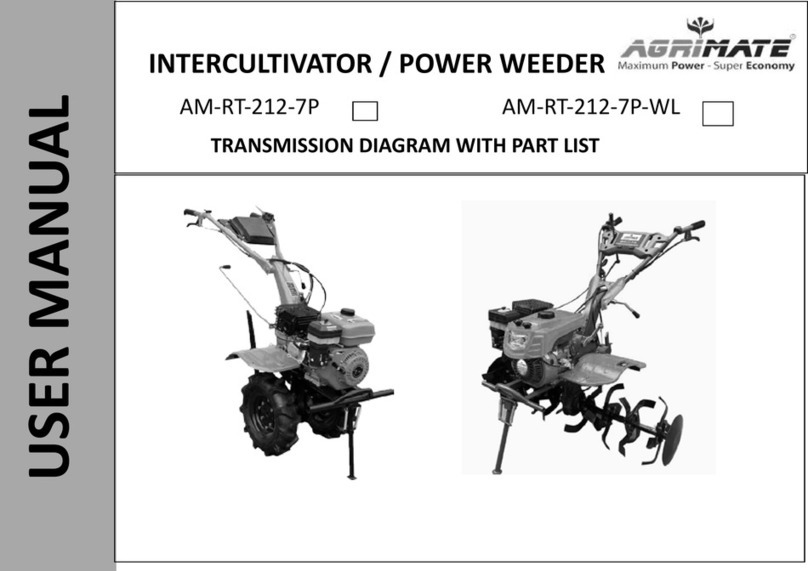
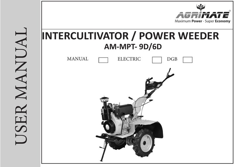
Agrimate
Agrimate AM-MPT-1100-6D User manual

Agrimate
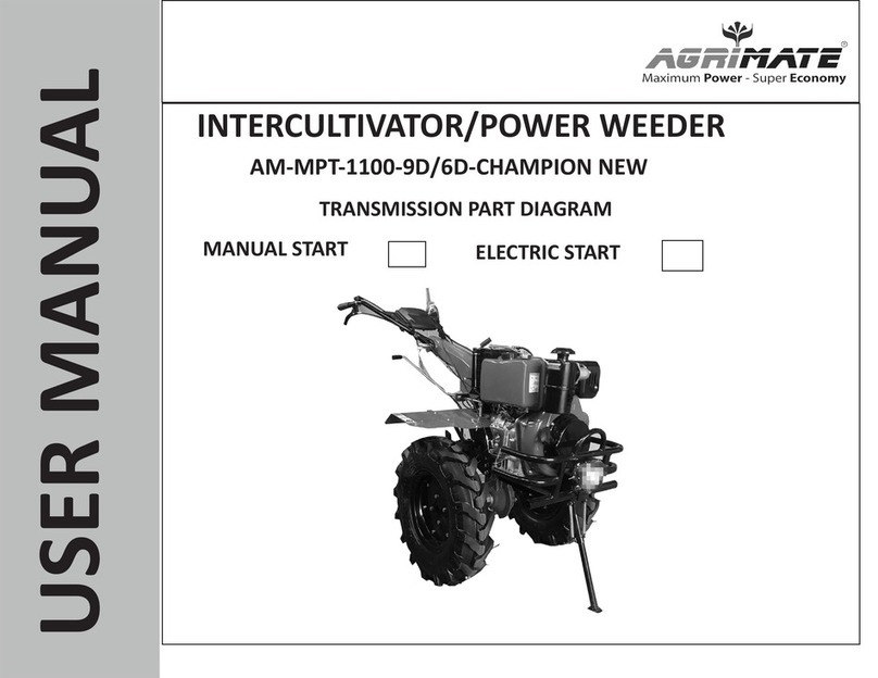
Agrimate AM-MPT-1100-9D/6D-CHAMPION NEW User manual

Agrimate
Agrimate AM-RT-212-7P User manual

Agrimate
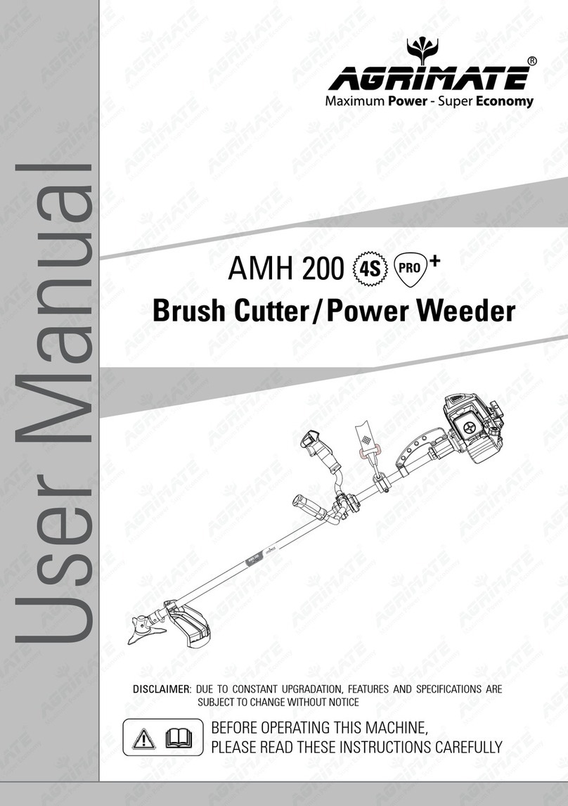
Agrimate AMH 200 User manual

Agrimate
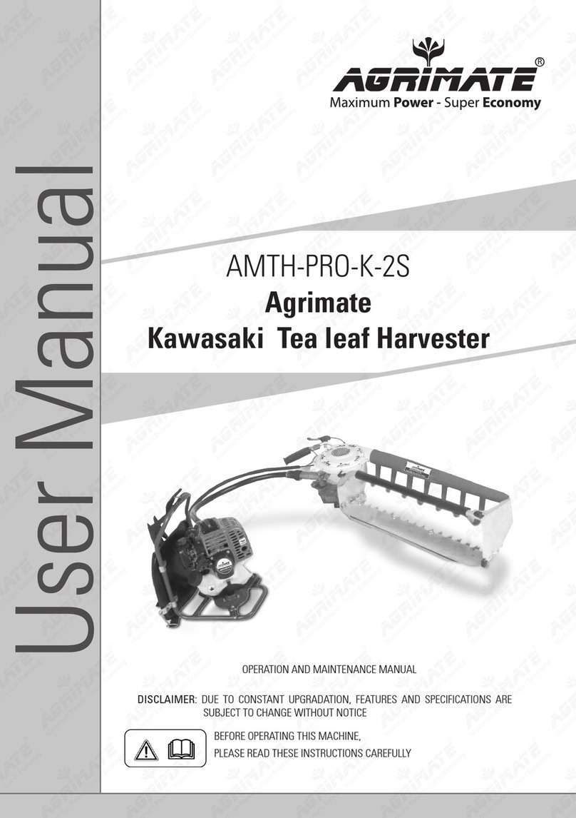
Agrimate AMTH-PRO-K-2S User manual
Agrimate
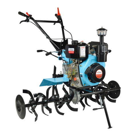
Agrimate AM-RTP-7P CHAMPION User manual
Agrimate
Agrimate AM-MPT-9D User manual
Agrimate
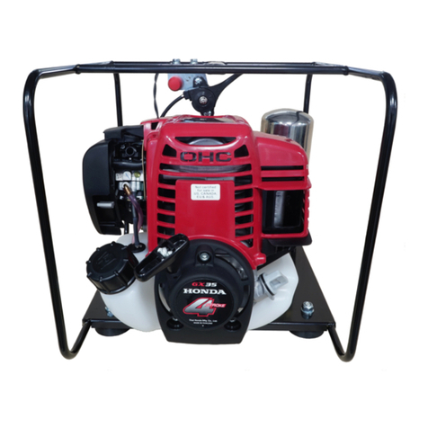
Agrimate AMH-P888-WITH GX-35-FF User manual
Popular Lawn And Garden Equipment manuals by other brands

DynaTrap
DynaTrap DT2000XLP owner's manual

DIG
DIG G77AS installation instructions

Genuine Factory Parts
Genuine Factory Parts 49M4260G953 Operator's manual

Sundown Audio
Sundown Audio JUMBO Series Operator and parts manual

Oypla GARDEN
Oypla GARDEN 3839 user manual

EINHELL
EINHELL BG-BC 33-4 S Original operating instructions