RSF Elektronik MS 35 MO User manual

MONTAGEANLEITUNG
MOUNTING INSTRUCTIONS
MS 35 MO, MK
Stahlmaßband lose oder
mit aufgezogenem Klebeband
Steel tape scale only
or with adhesive tape
Ausgabe 07/2022 Art.Nr. 1254792-01 Dok.Nr. D1254792-05-A-02
Für Montage des Abtastkopfes bitte separate Anleitung verwenden.
For mounting the scanning head, please use separate instructions.

02 MS 35 MO, MK
Seite / Page
1Einleitung ............................................................................................ 03
Introduction ........................................................................................... 03
2Technische Daten .......................................................................... 04 − 05
Technical data ................................................................................ 04 − 05
3Sicherheitshinweise .............................................................................. 06
Safety notes .......................................................................................... 06
4Montagevorbereitungen ........................................................................ 07
Mounting preparations ............................................................................ 07
5Montage ....................................................................................... 08 − 09
Mounting ........................................................................................ 08 − 09
6Schaltpunkte einstellen, Referenzmarke wählbar ...................................... 10
Switch points adjusting, selectable reference mark ...................................... 10
7Demontage, Umweltschutz, Entsorgung .................................................. 11
Demounting,environmental protection, disposal ......................................... 11
INHALT / CONTENT
Inhalt / Content

03
MS 35 MO, MK
Einleitung / Introduction 1
Die MS 35 Längenmessgeräte dürfen nur zur Ermittlung von Längen- bzw. Wegin-
formationen verwendet werden. Jeder andere Gebrauch kann Personen- bzw. Sach-
schäden verursachen!
The MS 35 linear encoders may only be used to determine length and path information.
Any other use may cause personal injury or property damage!
1.4 BESTIMMUNGSGEMÄßER GEBRAUCH / INTENDED USE
Lesen Sie die Montageanleitung sorgfältig und bewahren Sie sie gut auf.
Online verfügbar unter:
http://www.rsf.at/de/service-support/downloadbereich/
Carefully read the mounting instructions and keep them safely.
Online available at: http://www.rsf.at/en/service-support/downloads/
Dieses Symbol kennzeichnet wichtige Hinweise,
die Personenschäden verhindern.
This symbol indicates important information that prevents
personal injuries.
Dieses Signalwort kennzeichnet wichtige Hinweise,
die Sachschäden verhindern.
This signal word indicates important information that prevents
damage to property.
Dieses Symbol kennzeichnet nützliche Tipps, Empfehlungen
sowie zusätzliche Informationen.
This symbol indicates useful tips, recommendations and addi-
tional information.
Dieses Symbol kennzeichnet Handlungsanweisungen.
This symbol indicates instructions.
1.1 VORWORT / PREAMBLE
1.3 SYMBOLE / SYMBOLS
HINWEIS
NOTICE
1.2 KONFORMITÄT MIT RICHTLINIEN / DIRECTIVES CONFORMITY
RoHS-Richtlinie / RoHS-directive 2011/65/EU, 2015/863/EU
The Restriction of the Use of Certain Hazardous Substances in Electrical
and Electronic Equipment Regulations 2012

04 MS 35 MO, MK
2 Technische Daten / Technical data
2.1 SPEZIFIKATION / SPECIFICATION
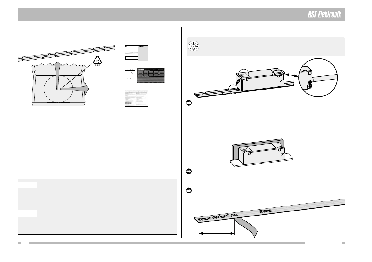
2.1.2 TYPENSCHILD / LABEL
MS 3x.x3MK: Produktname / Product name
ML: Messlänge / Measuring length
RI 24: Referenzmarkenlage / Reference mark position
SN: Seriennummer mit Änderungsindex, z. B. „A“
Serial number with change index, e. g. “A“
U8: Herstellungsdatum / Manufacturing date
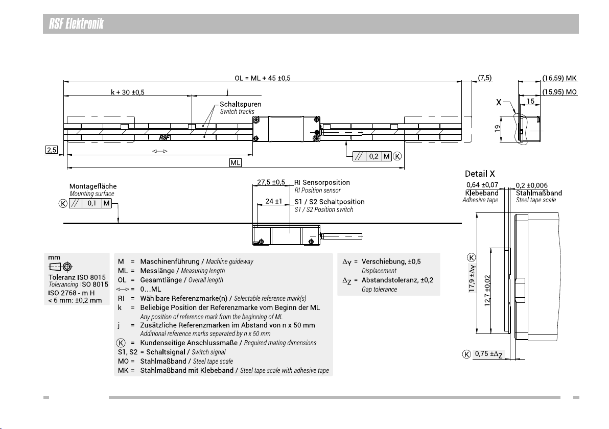
2.1.1 MAßVERKÖRPERUNG / GRADUATION CARRIER
Gerätetyp / Model
MS 35 MO = Stahlmaßband lose
Steel tape scale loose
MS 35 MK = Stahlmaßband mit aufgezogenem Klebeband
Steel tape scale with adhesive tape
Teilungsperiode / Grating period 20 µm
Genauigkeitsklasse / Accuracy grade ±5, ±15 µm/m
Wärmeausdehnungskoefzient
Coefcient of thermal expansion α ≈ 10 × 10-6 / K
Linearitätsabweichung / Non-linearity ±3 µm/m
Max. Messlänge
Max. measuring length 11 940 mm (größere Längen auf Anfrage) / (greater lengths on request)
Referenzmarken (RI)
Reference marks (RI)
Standard: 50 mm (äquidistant) / (equidistant)
An beliegiber Position, nach Kundenwunsch
At any position, on request
Position kundenseitig wählbar (Kunde aktiviert RI durch Abkleben)
Position selectable by customer (customer activates RI by covering)
Abstandskodiert auf Anfrage / Distance-coded on request
Vibration 55 Hz – 2000 Hz ≤150 m/s2(EN 60 068-2-6)
Schock / Shock 8 ms 1000 m/s2(EN 60 068-2-27)
Temperatur
Temperature
Lagerung / Storage: −10 °C bis / to +70 °C
Betrieb / Operation 0 °C bis / to +60 °C
Masse / Mass MO: 20 g/m, MK: 25 g/m
Schutzart EN 60529
Protection EN 60529
Die Maßverkörperungen haben keinen besonderen Schutz.
Sind sie einer Verschmutzung ausgesetzt,
müssen entsprechende Schutzmaßnahmen getroffen werden.
The graduation carriers have no special protection.
If the scales are exposed to contamination,
protective measures must be taken.
2.2 ZUBEHÖR / ACCESSORIES
2.2.1 BANDANBAUHILFE / TAPE MOUNTING TOOL
Montageanleitung TMT MS 35 MK: 1267573-01
Mounting Instructions TMT MS 35 MK: 1267573-01
Montagehilfe / Tape mounting tool TMT MS 35 MK, ID: 632926-01

05
MS 35 MO, MK
2.3 ABMESSUNGEN / DIMENSIONS
Technische Daten / Technical data 2

06 MS 35 MO, MK
3 Sicherheitshinweise / Safety notes
3.1 PERSONENSCHUTZ / PERSONAL SAFETY 3.2 GERÄTESCHUTZ / DEVICE SAFETY
HINWEIS
NOTICE
Reinigungsmittel Stahlmaßband / Cleaning agents steel tape scale
Erlaubt / Allowed Verboten / Prohibited
Weiches, fusselfreies,
nicht scheuerndes Putztuch
Soft, lintfree, not rubbing cloth
Scheuer- und Poliermittel
Abrasives, polishes
Hochprozentige, alkoholische Reini-
ger oder Lösungsmittel, z. B. Aceton,
(Iso)Propanol, Ethanol
High-proof alcoholic cleaners or
solvents, e. g. acetone, (iso)propanol,
ethanol
Aggressive oder korrosive Mittel,
z. B. starke Säuren, Ammoniak
Aggressive or corrosive media,
e. g. strong acids, ammonia
Stellen Sie sicher, dass sich im gesamten Messbereich weder
Maschinenteile noch Fremdkörper jeglicher Art benden, um
Beschädigungen am Längenmessgerät vorzubeugen.
Make sure that neither machine parts nor foreign objects are
within the measuring range in order to prevent damages to the linear
encoder.
Die Montage der Längenmessgeräte erfordert gute mechanische und elektronische
Kenntnisse und eine präzise und sichere Arbeitsweise! Die Montage ist nur durch
eine ausgebildete Fachkraft unter Einhaltung der örtlichen Sicherheitsbestim-
mungen durchzuführen!
The mounting of the linear encoders requires great mechanical and electronical
knowledge, moreover precise and safe operation! Therefore, mounting should only
be carried out by a qualied specialist in compliance with local safety regulations!
Schalten Sie alle von der Montage bzw. Reparatur betroffenen Geräte /
Maschinen / Anlagen vollständig ab! Trennen Sie die Geräte /
Maschinen / Anlagen gegebenenfalls vom Stromnetz und machen Sie
die Pneumatik drucklos!
Before mounting, switch off all the devices / machines / plants affected.
If appropriate, isolate the devices / machines / plants from the mains and
remove the pressure from pneumatic.
BenützenSiegeeignete SchutzausrüstungfürdieMontage /Demontage
(Handschuhe, Schutzbrille).
Wear suitable protective equipment for mounting / demounting
(gloves, goggles).

07
MS 35 MO, MK
Montagevorbereitungen / Mounting preparations 4
4.1 ZÄHLRICHTUNG / COUNTING DIRECTION
Kabel / Cable
Referenzmarke
Reference mark
4.2 VERFAHRWEG / MACHINE TRAVEL
4.3 MONTAGEFLÄCHE / MOUNTING SURFACE
+
Reinigen Sie die Montagefläche vor der Montage.
Sie muss sauber, fett- und lackfrei sein.
Clean the mounting surface before mounting.
It has to be clean and free of grease or varnish.
Fräsen Sie eine Führungsnut oder bringen Sie Anschlagstifte als
Montageflächeander Maschinean. AnforderungenandieMontage-
flächen siehe Abmessungen (s. S. 05).
Mill a guide groove or mount stop pins as a mounting surface onto
the machine. Demands for mounting see in dimensions
(see page 05).
Wählen Sie den Anbau so, dass der Verfahrweg der Maschine
innerhalb der Messlänge (ML) des Messgeräts liegt.
Außerhalb der Messlänge kann es zu Fehlmessungen oder
einem Ausfall der Zählsignale kommen.
When mounting the linear encoder make sure, that the machine
travel is within the allowed measuring length (ML) of the encoder.
Operating the encoder beyond the measuring length can cause
incorrect measurements or a failure of the counting signals.
0
(7,5)
2,5
ML
Bewegungsrichtung des Abtastkopfes für positive Zählrichtung
Direction of motion of the scanning head for positive counting direction

08 MS 35 MO, MK
HINWEIS
NOTICE
MONTAGEANLEITUNG
MOUNTINGINSTRUCTIONS
MS 35 MO, MK
Stahlmaßbandlose oder
mitaufgezogenem Klebeband
Steeltape scale only
orwith adhesive tape
Ausgabe 07/2018 Art.Nr. 1254792-01 Dok.Nr. D1254792-00-A-01
FürMontage des Abtastkopfes bitte separate Anleitung verwenden.
Formounting the scanning head, please use separate instructions.
AK MS 35: 1254746-01
5 Montage / Mounting
5.1 GERÄT AUSPACKEN / UNPACK ENCODER
Montieren Sie das TMT MS 35 MK anstelle des MS 35 Abtastkopfs.
Legen Sie die mitgelieferte Abstandsfolie (Dicke: 1,6 mm) unter
die Montagehilfe, um den Arbeitsabstand einzuhalten.
Mount the TMT MS 35 MK instead of the MS 35 scanning head.
Insert the supplied gap foil (thickness: 1,6 mm) under the mounting
tool to observe the working gap.
Entfernen Sie die Abstandsfolie nach dem Montieren des TMT.
Remove the gap foil after mounting the TMT.
Ziehen Sie die Schutzfolie vom Klebeband ungefähr 80 mm ab.
Remove protective foil from adhesive tape approximately 80 mm.
Beschädigungsgefahr durch Knicken des Stahlmaßbands!
Das Stahlmaßband verfügt über eine feine Teilungsstruktur.
Beachten Sie den kleinst zulässigen Biegeradius:
60 mm
Risk of damage due to fold the steel tape scale!
The steel tape scale has a ne grating structure.
Observe the smallest permissible bending radius:
60 mm
B
C
A
AMS 3x MO, MK Stahlmaßband / MS 3x MO, MK steel tape scale
BMontageanleitung / Mounting instructions
CAbdeckband für Schaltspur, Aktivierungssticker Referenzmarken
Cover tape for switch track, activation sticker reference marks
DHersteller-Prüfzertikat / Manufacturer’s inspection certicate
EVerpackung / Packaging
Montieren Sie das Band mit der Montagehilfe TMT MS 35 MK.
Mount the tape scale by use of the mounting aid TMT MS 35 MK.
80 mm
D
Wellpappe
Corrugated
cardboard
E
5.2 STAHLMAßBAND MONTIEREN
MOUNTING THE STEEL TAPE SCALE

09
MS 35 MO, MK
Montage / Mounting 5
Führen Sie das Stahlmaßband durch das TMT MS 35 MK.
Thread the steel tape scale through the TMT MS 35 MK.
Verfahren Sie das TMT MS 35 MK mit einer gleichmäßig langsamen
Geschwindigkeit entlang der Achse.
Move the TMT MS 35 MK at a steady slow speed along the axis.
Halten Sie den Beginn des Stahlmaßbands über die ersten 100 mm fest.
Hold the beginning of the steel tape scale over the rst 100 mm.
Enfernen Sie das TMT MS 35 MK.
Remove the TMT MS 35 MK.
Drücken Sie das Stahlmaßband mit einem Anpressdruck von ~20 N/cm² an.
Press down the steel tape scale with a contact pressure of ~ 20 N/cm².
Beachten Sie die idealen Bedingungen zur Haftung des Klebebands:
Verklebungstemperatur: min. +18 °C/+64 °F / max. +38 °C/+100 °F
Max. Endklebekraft nach ca. 72 h.
Observe the ideal conditions for tape adhesion:
Adhesion temperature: min. +18 °C/+64 °F / max. +38 °C/+100 °F
Max. bond strength after approx. 72 h.
Ziehen Sie die Schutzfolie vom Stahlmaßband ab.
Strip away the protective foil of the steel tape scale.

MS 35 MO, MK
10
6 Schaltpunkte einstellen, Referenzmarke wählbar / Switch points adjusting, selectable reference mark
6.1 ABDECKBÄNDER POSITIONIEREN / COVER TAPES POSITIONING 6.2 ABDECKBÄNDER POSITIONIEREN / COVER TAPES POSITIONING
REFERENZMARKE (RI) AUSWÄHLEN / SELECT REFERENCE MARK
Wählen Sie die Position der Schaltpunkte in beiden Schaltspuren aus.
Select the position of the switch points in both switch tracks.
Wählen Sie die Position der Schaltpunkte in der unteren Schaltspur aus.
Select the position of the switch points in the lower switch track.
Wählen Sie die Position der Referenzmarke (RI) in der oberen Spur aus. Aktivieren
Sie sie durch Aufkleben eines RI-Aktivierungsstickers in der Kennzeichnung vor der
Referenzmarke. Innerhalb der Messlänge (ML) ist eine beliebige RI-Position (k)
möglich - zusätzliche Referenzmarken (j) sind im Abstand von 50 mm frei wählbar.
Select the position of the reference mark (RI) in the upper track. Activate it by
sticking an RI activation sticker inside the marking in front of the reference mark.
Within the measuring length any RI-position (k) is possible - additional reference
marks (j) can be selected at a distance of 50 mm.
BEISPIEL / EXAMPLE
S1: 20 mm vom Beginn ML / S1: 20 mm from beginning of ML X1L = 26 mm
S2: 40 mm vor Ende ML / S2: 40 mm before end of ML X2R =79 mm
S1 = Schaltpunkt Signal S1 vom Beginn ML
Switch point signal S1 from beginning of ML
X1L = Aktivierungsbandlänge = S1 + 6
Activation tape length = S1 + 6
S2 = Schaltpunkt Signal S2 vor Ende ML
Switch point signal S2 before end of ML
X2R = Aktivierungsbandlänge = S2 + 39
Activation tape length = S2 + 39
Ausgewählte
Referenzmarke
ist aktiviert
Selected
reference mark
is activated
0 ±10 ±1
4 ±0,2
4 ±0,2
0,15 ±0,15
0,15 ±0,15
4 ±0,2
0,15 ±0,15
RI-Aktivierungssticker
RI-activation sticker
Schaltspur 2 / Switch track 2
4020 S2S1
X1LX2R
X2R
X2L
Messlänge (ML)
Measuring length (ML)
Schaltspur 1 / Switch track 1
Messlänge (ML) / Measuring length (ML)
k + 30 ±1 j
Referenzmarke (RI)
Reference mark (RI)
RI-Aktivierungssticker
RI-activation sticker
Referenzmarkenspur / Reference mark track
Schaltspur / Switch track
Kennzeichnung für
RI-Aktivierungssticker
Marking for
RI-activation sticker

11
MS 35 MO, MK
Demontage, Umweltschutz, Entsorgung / Demounting, environmental protection, disposal 7
7.1 DEMONTAGE / DEMOUNTING
VORSICHT Gefahr durch Splitter und scharfe Kanten!
Bei Nichtbeachtung können Verletzungen entstehen!
Benützen Sie geeignete Schutzausrüstung für die Demontage
(Handschuhe, Schutzbrille).
Biegen / verformen Sie Maßbänder nicht zu stark.
Beachten Sie Sicherheitsdatenblätter von Lösungsmitteln.
CAUTION Danger from splinters and sharp edges!
Non-observance could cause injuries!
Wear suitable protective equipment for removal
(gloves, goggles).
Do not bend or deform scale tapes excessively.
Comply with the safety data sheets of solvents.
Verwenden Sie folgende Hilfsmittel zum Demontieren der Maßverkörperung:
Heißluftföhn mit Temperaturregelung, alternativ: Heizplatte mit Temperaturregelung
Bandstahl oder Metallfolie oder Fühlerlehrenband mit einer Dicke von 0,04 mm
bis 0,3 mm (bzw. halb so dick wie das verwendete Klebeband)
Alternativ: geflochtene Angelschnur (mehrfach geflochten, Durchmesser≤ 0,13 mm),
Stahldraht (Durchmesser ≤ 0,13 mm) oder Zahnseide
Lösungsmittel: 2-Propanol (Isopropanol), Ethanol, Aceton, Methyl-Ethyl-Keton
Klingenmesser mit dünner Klinge oder Skalpell
Rasierklingen mit Einspannung oder mit Halter (z. B. Ceranfeldschaber)
Kunststoffspachtel oder Kunststoffschaber
Abziehstein oder Schleifstein
Weiche, silikon- und trennmittelfreie Tücher
Lederhandschuhe oder lösemittelbeständige Handschuhe
Use the following tools and equipment to perform the demounting of the graduation carrier:
Hot-air gun with temperature control, alternative: heating plate with temperature control
Strip steel or metal foil or feeler gauge strip with a thickness of 0.04 mm to 0.3 mm
(or half as thick as the adhesive tape used)
Alternative: Braided fishing line (multi-braided, ≤ 0.13 mm diameter),
steel wire (≤ 0.13 mm diameter) or dental floss
Solvents: 2-propanol (isopropanol), ethanol, acetone, methyl ethyl ketone
Safety cutter with thin blade or craft knife
Razor blades with fixture or holder (e.g. cooktop scraper)
Plastic scraper or plastic putty knife
Whetstone
Soft cloths free from silicones and release agents
Leather gloves or solvent-resistant gloves
Die Demontage des Geräts darf nur durch Fachpersonal vorgenommen werden. Demounting of the product is only to be performed by qualied personnel.
7.2 UMWELTSCHUTZ UND ENTSORGUNG / ENVIRONMENTAL PROTECTION AND DISPOSAL
Umweltschäden durch falsche Entsorgung des Geräts, Zubehörs
oder Peripheriegeräten!
Entsorgen Sie nicht im Hausmüll.
Entsorgen Sie Elektroschrott und Elektronikkomponenten nur
durch autorisierte Annahmestellen. Sie unterliegen der Sonder-
müllbehandlung.
Beachten Sie die Vorschriften des jeweiligen Landes.
Genaue Informationen zu gesetzlichen Regelungen gibt
die zuständige Verwaltungsbehörde.
Environmental damage due to incorrect disposal of the product,
accessories or peripherals!
Do not dispose in domestic waste.
Dispose only by authorized collection points. Electrical waste and
electronic components are subject to special-waste regulations.
Observe the applicable country-specific regulations.
More detailed information on legal regulations can be obtained
from competent authorities.
NOTICE
HINWEIS

Ges.m.b.H.
Ausgabe 07/2022 Art.Nr. 1254792-01 Dok.Nr. D1254792-05-A-02
Certied acc. to
ISO 9001
ISO 14001
Elektronische Längen- und Winkelmessgeräte,
Präzisionsteilungen
Tarsdorf 93, 5121 Tarsdorf, Österreich
+43 (0)6278 / 8192-0
FAX
+43 (0)6278 / 8192-58
e-mail: [email protected]
internet: www.rsf.at
This manual suits for next models
1
Table of contents
Other RSF Elektronik Scale manuals

RSF Elektronik
RSF Elektronik MS 25 MP User manual

RSF Elektronik
RSF Elektronik MS 25 BO User manual

RSF Elektronik
RSF Elektronik MS 35 BA User manual

RSF Elektronik
RSF Elektronik MS 15 GO User manual

RSF Elektronik
RSF Elektronik MS 45 MP User manual

RSF Elektronik
RSF Elektronik MS 25 BA User manual

RSF Elektronik
RSF Elektronik MS 35 BK User manual

RSF Elektronik
RSF Elektronik MS 15 MK User manual

RSF Elektronik
RSF Elektronik MS 25 MO User manual