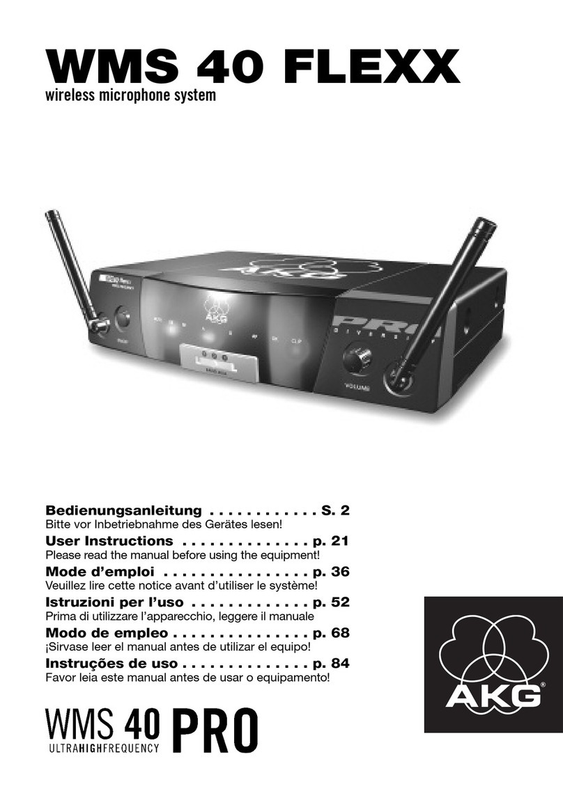
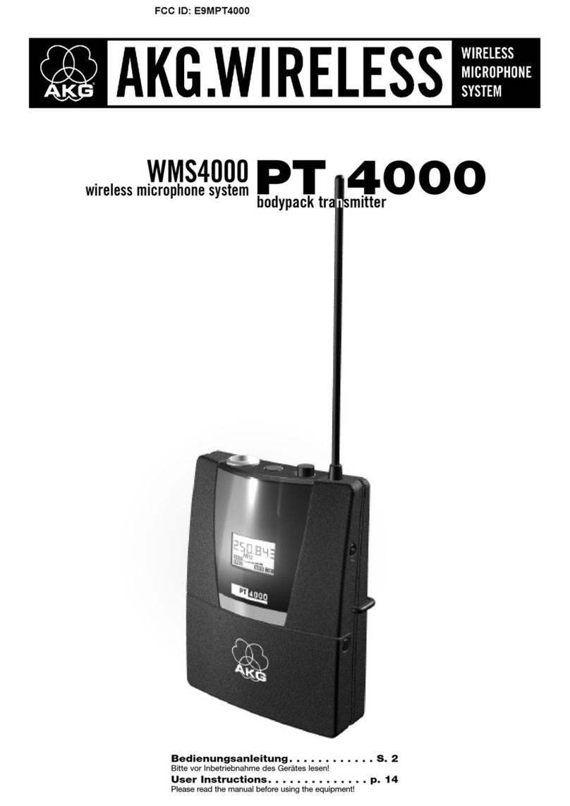
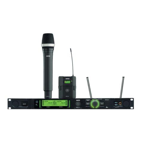
AKG WMS 4000 User manual

WMS 4000
Multichannel System
Schematic&PartList
1-32 Channel
WolfgangFritz /Feb. 2008
MCS0802001
1

Introduction
SRA2 B/W activedirectionalantenna
For Venues (tour sound&installs) thatcover largedistances (up to150m, 500 ft) like
music halls,stadiums and other openair applications.
RA4000B/W active omni-directional antenna
For Venues withouta designated transmitter area and up to 100m/330 ft freelineof
sight. Ideal for conference rooms, multi purpose halls, housesofworship etc.
Thefollowingschematics willhelpyou toeasily setup multichannelsystems.
Please use the equipmentthat isspecifiedin the schematicsonly.
For yourconvenience andunderstanding, we’veadded technicalinformation andpartlists.
You can usethis part lists whenordering thesystem you require! If you need any help
regardingthefrequencyregulationsorifyourparticularsituation doesn’tallowfora standard
All the WMS450 Systems in thisdocument aredesigned withactive antennasthatcan
used in all venueswith a 20mRG58 antenna cable.
WolfgangFritz /Feb. 2008
MCS0802001
2

Content
General InformationPage
Receiver/AntennaPlacement Information4
Squelch Information4
Intermodulation Information4
HUB4000Q-HiQnet SystemArchitect Information5
CableAttenuation Information6
PS4000dipswitch Information6
AB4000dipswitch Information6
PS4000dipSwitchMatrix Information7
RequiredComponentMatrix Information8
Glossar Information9
WMS SystemAntennaTypePage
58
61
64
67
50
52
54
56
42
44
46
48
34
36
38
40
26
28
30
32
18
20
22
24
10
12
14
16
Schematic / Part List
32ChannelSRA2B/W
32ChannelRA4000B/W
SRA2B/W
RA4000B/W
12
12 Channel
Channel
SRA2B/W
RA4000B/W
SRA2B/W
RA4000B/W
10Channel
10Channel
Channel9 9Channel
8ChannelSRA2B/W
8ChannelRA4000B/W
SRA2B/W
6ChannelRA4000B/W
6Channel
SRA2B/W
RA4000B/W
SRA2B/W
RA4000B/W
Channel
Channel
Channel
Channel
4
4
5
5
SRA2B/W4 4Channelno PSU4000
Channelno PSU4000RA4000B/W
2
2ChannelRA4000B/W
SRA2B/WChannel
1Channel
Channel1 2Channelno PS4000
2Channelno PS4000
SRA2B/W
RA4000B/W
SRA2B/W
RA4000B/W
16ChannelSRA2B/W
16ChannelRA4000B/W
24ChannelSRA2B/W
24ChannelRA4000B/W
WolfgangFritz /Feb. 2008
MCS0802001
3

TechnicalInformation
Wireless Basics
Every wireless microphone system hastooperate on one specific frequency
Transmitter and receiver of a systemneed toworkon the same frequency
Two transmitters cannot be used with one receiver at the same time
Receiver/AntennaPlacement
Direct line ofsight between transmitter andreceiver antenna
Place the receiver/antennas at least 5 ft.(1.5m) awayfrom alltransmitters
Place the receiver antennas atleast5 ft. (1.5 m)away fromanybig metal object,
wire(particularly wire mesh)or sheet metal structures,walls, ceilings,etc.
Donotplace the antennas in hiddenplaces(behindwalls)
Place the receiver at least5 ft. (1.5 m) away from any equipment that mayemit RF
radiation suchas lighting racks, fluorescent lamps, digitaleffectunits,or PCs
Squelch
Standard:Carrier squelch,manual
– Operates strictlyon thesignalstrength of the signal.
– If received signalstrength drops under the adjustable squelch threshold the
audiooutputis muted
Advanced:Tone Code (onlyWMS4000)
– The audioturns on only in the presence of the correcttone code and an
adequate signal strength(-100dbm)
– Lock out all signals except ones with the correct key.
Intermodulation
Intermodulationistheresult of two or more signals of differentfrequencies being
mixed together, forming additional signals thatarenotharmonic frequencies of
either.
By using more than onetransmitter simultaneously at the same location,intermodulation
happens in the receiver and/or transmitter. Inyourcasethis intermodulationproducts
aregenerated in the bandwidth that you are using.
To avoid intermodulating frequencies, we offeryou pre-calculated frequencies as presets in
theSR450 and SR4000 Receiver.Please, make sure thatwhen settingupa multi channel
system, all your receivers are set tothe same countrypreset(NAME) andgroup. Usethe
Automatic channel function (auto setup)toscanfor free frequencies at your venue.
WolfgangFritz /Feb. 2008
MCS0802001
4
HUB 4000 Q
The HUB 4000Q addsHiQnet functionality to anAKGwirelesssystem (SR 4000, SST 4 and
upcoming devicesare supported).For largewirelesssystems multiple HUB 4000 Q’s can be used and
controlled fromasingle computer.With connecting theHUB 4000 Q to a HiQnetnetwork the useris
able to monitorand controlan AKGwireless system fromacomputer running System Architect.
HiQnet SystemArchitect
The simpleand easyto useuser interfaceofthe HUB4000Q plug inwithin System Architect allows
the userto setup and configure the wireless systemeasy andfastwith toolslike Auto Setup,
EnvironmentScan, RFMonitor andDeviceManager.
HiQnetSystem Architect alsoallows custom configuration of custom madeuser interfaces which
makes it aperfect tool forinstalledsoundand tour sound applications.
Today'sHiQnet system is builtfrom flagshipproducts fromHarmanPro brands AKGAcoustics,
BSSAudio, Crown International, dbx Professional,JBL Professional,Lexicon Pro,Soundcraftand
Studer.
AKGUser Interface
DeviceManager – Frequency Management
Enviroment Scan -Frequency Graph
automaticidentification of allHUB4000Q’s
Simpleand easyto usechannel-oriented user interface
Fast andintuitive setupand configuration of frequencymanagementwith AutoSetup,
EnviromentScan and DeviceManager
Offline configuration
Saveand load yoursetup
Features
WolfgangFritz /Feb. 2008
MCS0802001
5

RG58 Cable Attenuation(MKPS,MKA5, MKA20 antennacable)
CableAttenuation
Toobtain the best sound possible,you needtohavetheright RF inputlevel throughout
your signal chain. Premium quality wireless systems like the WMS450 and WMS4000,
offeryou adjustable RF-level settings that garanteetomaximise operating distance even
whenusing different cablelenghts and different types of cable! Forthis purpose,AKG’s
PS4000W antenna splitter, has3 dip switches that you’ll findon the right sideof it’s
frontpanel, behind the AKG logo.
PS4000dipswitch
This dip switch reduce the input RFlevel of thePS4000between 0 dBand 14dB.
Allantennaoutput level and thecascade(link)output levelhavean effectonthis reduction.
AB4000 dip switch
TheAB4000has a fix17.5dBamplifier in the outputstage. The dipswitch reducethe
input RF level of the AB4000 between 0 dBand -14 dB. AB4000 get theDC power
through the antenna cable from the PS4000 or an ASU4000 unit.
Rear View
4xAntenna A output
(DC power)
Antenna A input Ant. B
AntennaA cascade output
(DCpower)
dip switches behind AKG Logo
Signal leveladjustment
Attenuation
PS4000W – Power Splitter
AB4000 – Antenna Booster
WolfgangFritz /Feb. 2008
MCS0802001
Signallevel adjustment
Internal
Attenuation Total Gain
3.5 dB
5.5 dB
7.5 dB
9.5 dB
11.5dB
13.5dB
15.5dB
17.5dB
6

3x MKA 20
60m/198ft
AntennaBooster
AB4000
necessary !
4x MKA 20
80m/264ft
AntennaBooster
AB4000
necessary !
MKA 5
5m/16ft
MKA 20
20m/ 66ft
MKA 5 + MKA 20
25m/ 82ft
2x MKA 20
40m/132ft
Cable type
&
Length
0110E0189
1m/ 3ft
PS4000 dipswitchmatrix (RG58 cable)
RA4000 WSRA2 W RA4000 BWSRA2 BW
Passiv Antennas Active Antennas
Antenna type
&
Gain
0 dB
0 dB 0 dB -4dB
0 dB -2dB -14 dB
-8dB -12 dB
-6dB -10 dB
0 dB
0dB -2 dB
RA4000BW
2xMKA20
AB4000
0dB
PS4000
-4dB
1xMKA20
SRA2 BW
2xMKA20
AB4000
0 dB
PS4000
-8 dB
1xMKA20
RA4000BW
2xMKA20
AB4000
0dB
PS4000
0dB
2xMKA20
SRA2 BW
2xMKA20
AB4000
0 dB
PS4000
0 dB
2xMKA20
1 dB4-6dB18 dB22-24 dB
¼wave
UHF Antenna
Youhaveto use thisPS4000 dipswitch settings at all PS4000 withdirect connection
totheantennas.
All cascade PS4000 havethe same dip switchsetting ON/ON/ON (0dB)
WolfgangFritz /Feb. 2008
MCS0802001
7

Number of …
PS4000ZAPD-21MKPSPSU4000
AC12 Power
SupplyPSU01/4000
AC12Power
SupplyHUB4000Q
21040+31+01
31060+41+01
41081+01+01
510101+01+11
620141+02+01
720161+02+01
820181+02+01
920201+02+12
1030241+03+02
1130261+03+02
1230281+03+02
1330301+13+12
1442362+04+02
1542382+04+02
1642402+04+02
1742422+04+13
1842442+04+23
1952522+05+03
2052542+05+03
2152562+05+13
2252582+05+23
2362622+06+03
2462642+06+03
2562662+16+14
2662682+26+24
3290803+09+04
3690883+49+45
481301205+013+06
521301285+213+46
Additional you will need min.2xantennasand2xMKAxxantennacables!
Please, lookatthe"PS4000dipswitchmatrix(RG58)" to findyour antennacomponents.
PSU01/4000 isa12V/2APower SupplyAdapter (1xPSU4000=3xPSU01/4000)
WMS
Receiver
Standard Power Supply !onlyavailableinUS!
Power Supply
WolfgangFritz /Feb. 2008
MCS0802001
WMS450/4000 ComponentMatrix
8

Glossar
SR4000 – WMS4000Stationary Receiver
PS4000W – PowerSplitter 1:4 (Distribute RF signaland DC Power)
Splits 1 antenna to 4 receiver
Antenna cascade(Link) output tosend RF-Signal to next PS4000.
Cascade max. 3 PS4000.
If you need more than 12 channelsuse an ZAPD in front of the first PS4000.
PSU4000 –Power SupplyUnitwith 3x 12volt outputs (2.5A and 2A)
SRA2B/W –ActiveDirectional Antenna (21dBGain)
RA4000B/W –ActiveOmni-directional Antenna(18dBGain)
HPA4000 – Headphone Amplifier (8xstereojack inputs, 1 HPoutput)
CU400 –Charging Unit for WMS400/450 (2transmitter /unit)
ZAPD-21 – Passive Combiner 2:1and 1:2
MKPS –0.65m/2 feet RG58 antennacable
MKA20 – 20/66ft RG58antenna cable
ASU4000 –Antenna Supply Unit
Suppliesup tothree activeelements (RA4000BW, SRA2BW, AB4000)
0110E01890 –Front assembly cable
Install¼ wave antennas at the frontofthe rack
AB4000 – AntennaBooster
3.5 dB – 17.5dB amplifier
Front assembly cable& ¼waveantenna
WolfgangFritz /Feb. 2008
MCS0802001
Cable
MKA5 – 5m/16ftRG58 antenna cable
SR4000
XLR
AUDIO OUT
ANTA IN
DC IN (12V/0.5A) ¼“TS
AUDIO OUT
ANTB IN
Mixer
DATA
LOGIC OUT
1A
1B
2A
2B
3A
3B
4B
4A
ANTA INANT B IN
DC IN (12V/0.5A)
PS4000W
CASCADE A
CASCADE B
DC OUT 1 (2.5A)
AC POWER
PSU4000
DC OUT2(2A)
DC OUT3(2A)
~90-230V
SRA2 B/W
ANTOUT
RA4000B/W
ANTOUT
HPA4000
DC IN (12V/0.5A)Headphone
SR1
SR2
SR3
SR4
SR5
SR6
SR8
SR7
CU4000
DC IN (12V/1.4A)
ZAPD-21
A
S
B
ASU4000
ANT OUT
ANTIN
DC IN(12V/0.5A)
AB4000
ANT OUT
ANT IN
HUB4000Q
DC IN (12V/0.5A)ETHERNET
DEV1
DEV2
DEV3
DEV4
DEV5
DEV6
DEV8
DEV7
HUB4000Q –NetworkConcentrator for 8 devices(SR4000 or SST4)
Operate with Harman „System Architect“ software - http://hiqnet.harmanpro.com
9

2 HT4000 orPT4000 charging system (optional)
Project
Designer
Date Revision
1channel WMS4000 system
(SRA2 B/W – Antennas)
Wolfgang Fritz
02.02.2008 1.0
Build document1.0
Ref.No. MCS0802001
K171Studio Headphone
Headphone amplifier(optional)
1Channel WMS4000System
With directional antennas &40m antennacable (132feet)
HPA4000
DC IN(12V/0.5A)Headphone
SR1
SR2
SR3
SR4
SR5
SR6
SR8
SR7
AC12 Power Supply (500mA)
ASU4000
ANTOUT
ANTIN
DC IN(12V/0.5A)
AC12Power Supply (500mA) ASU4000
ANT OUT
ANTIN
DC IN (12V/0.5A)
AC12 PowerSupply(500mA)
2xMKPS
BNCI-connector
Available e.g. www.rs-components.com,
Ordernumber 112-1798
BNC I-connector
Available e.g. www.rs-components.com,
Ordernumber 112-1798
2x MKA20
(BNCI-connector is necessary tolink cables!)
2x MKA20
(BNC I-connector is necessaryto link cables!)
SRA2B/W
ANTOUT
SRA2B/W
ANT OUT
SR4000
XLR
AUDIO OUT
ANTA IN
DC IN (12V/0.5A) ¼“TS
AUDIO OUT
ANTB IN
Mixer
DATA
LOGICOUT
AC12 Power Supply (500mA)
Network Concentrator (optional)
HUB4000Q
DC IN(12V/0.5A)ETHERNET
DEV1
DEV2
DEV3
DEV4
DEV5
DEV6
DEV8
DEV7
CU4000
DC IN (12V/1.4A)
AC-CU4000 Power Supply(1.4A)
DHCPSwitch
DC IN
DEV 1
DEV 2
DEV 3
DEV 4
DEV 5
DEV 6
DEV 8
DEV 7
PC
10

Wolfgang Fritz/ Feb. 2008
MCS0802001
unitsdescriptioncommentcode
1
70
Half-rack receiverwithoutAC-Adapter; (frequency range 650 to863 MHz);ColourCoding Kit; 2
UHFantennas;RMU4000 rack mounting kit 3000Z00..
1
48
Hand-heldtransmitter or Bodypacktransmitter;(frequency range 650 to863 MHz);SA 63stand
adapter;2AA sizedrybatteries,Colour Coding Kit
Donot forget microphone headheadsetorother microphone!!
3001Z00..
3002Z00..
2
72
Externaldirectionalactive"paddle" antenna withamplifier(2 req.)3009Z0001
2
54
Connecting cableforPStoSR2.15ft(65cm)6000H0206
4
55
66 ft.(20m)Cablesforconnecting ext. antennas tomulti-couplers(2 req.)KOAXRG586000H0205
2
10
Antenna Supply unitforlong antennacables(BNCconnector)withoutAC-Adapter3009Z0010
3
4
12VAC-Adapterfor 1PS 4000, ASU4000,HUB4000, HPA 4000 orSR4000.7801H000…
2
BNCI-connector EXTERNAL !!Notavailable atAKG
-BNCI-Connector
(you can buy itat www.rs-components.com,Ordernumber112-1798)
unitsdescriptioncommentcode
1
39
Twincharger+ 2BP4000for HT4000 &PT4000;withACAdapter. Pleasespecify one ofthe
AC-CU4000 2887Z0004
1
45
Headphone monitoring amplifier-8 receiversins; &selectableoutwithout ACAdapter2998Z0004
1
85
Closed-back circum-auraldynamic stereo headphone, miniXLRconnector,detachablecable2908Z0001
2
4
12VAC-Adapterfor 1PS 4000, ASU4000,HUB4000, HPA 4000 orSR4000.7801H000…
1
7
12VAC-Adapter(EU-Version)powersupplyCU4000, PS4000 (you can alsouseaPSU4000
output) 7801H000…
1
50
NetworkconcentratorwithoutAC-Adapter;of8systems2955Z0014
1
DHCP NetSwitch+CAT5Cable EXTERNAL !!Notavailable atAKG
-for4input to1output (e.g.D-Link)
1Channel WMS4000Systemwithdirectional antennas, no PSU4000, no PS4000
Optional Components(Charging System&HeadphoneAmplifier)
Do not forgetmicrophonehead,headsetorother microphone!!
HT4000:e.g.D5WL-1, D3800 WL-1,C5WL-1, C535 WL-1, C5900WL-1
PT4000:e.g.C555L, C520ML,C516ML, C518ML,C519ML, HC577WR-L,CK77WR-L,CK55L, C411L, C417L
CU 4000
SRA2 B/W
SR 4000
MK PS
MKA20
HPA4000/ none
K171 Studio
AC 12
ASU 4000(BNC/none)
AC 12
HT4000orPT4000
HUB 4000Q/ none
AC-CU 4000
11

2 HT4000 orPT4000 charging system (optional)
Project
Designer
Date Revision
1channel WMS4000 system
(RA4000B/W – Antennas)
Wolfgang Fritz
02.02.2008 1.0
Build document1.0
Ref.No. MCS0802001
Headphone amplifier(optional)
1Channel WMS4000System
withomni-directional antennas & 25mantenna cable(82feet)
HPA4000
DC IN(12V/0.5A)Headphone
SR1
SR2
SR3
SR4
SR5
SR6
SR8
SR7
AC12PowerSupply(500mA)
AC12 Power Supply (500mA)
RA4000B/W
ANTOUT
RA4000B/W
ANT OUT
ASU4000
ANTOUT
ANTIN
DC IN(12V/0.5A)
AC12Power Supply (500mA) ASU4000
ANT OUT
ANTIN
DC IN (12V/0.5A)
AC12 PowerSupply(500mA)
2xMKPS
BNCI-connector
Available e.g. www.rs-components.com,
Ordernumber 112-1798
BNC I-connector
Available e.g. www.rs-components.com,
Ordernumber 112-1798
1x MKA20 + 1x MKA5
(BNCI-connector is necessary tolink cables!)
1x MKA20 + 1x MKA5
(BNC I-connector is necessaryto link cables!)
AC12PowerSupply(500mA)
K171Studio Headphone
SR4000
XLR
AUDIO OUT
ANT A IN
DC IN(12V/0.5A) ¼“ TS
AUDIO OUT
ANTB IN
Mixer
DATA
LOGIC OUT
Network Concentrator (optional)
HUB4000Q
DC IN (12V/0.5A)ETHERNET
DEV1
DEV2
DEV3
DEV4
DEV5
DEV6
DEV8
DEV7
CU4000
DC IN (12V/1.4A)
AC-CU4000 Power Supply(1.4A)
DHCPSwitch
DC IN
DEV 1
DEV 2
DEV 3
DEV 4
DEV 5
DEV 6
DEV 8
DEV 7
PC
12

Wolfgang Fritz/ Feb. 2008
MCS0802001
unitsdescriptioncommentcode
1
70
Half-rack receiverwithoutAC-Adapter; (frequency range 650 to863 MHz);ColourCoding Kit; 2
UHFantennas;RMU4000 rack mounting kit 3000Z00..
1
48
Hand-heldtransmitter or Bodypacktransmitter;(frequency range 650 to863 MHz);SA 63stand
adapter;2AA sizedrybatteries,Colour Coding Kit
Donot forget microphone headheadsetorother microphone!!
3001Z00..
3002Z00..
2
66
Externalomni-directionalactivedipoleantennawithamplifier(2req.)2632Z0030
2
54
Connecting cableforPStoSR2.15ft(65cm)6000H0206
4
55
66 ft.(20m)Cablesforconnecting ext. antennas tomulti-couplers(2 req.)KOAXRG586000H0205
2
10
Antenna Supply unitforlong antennacables(BNCconnector)withoutAC-Adapter3009Z0010
3
4
12VAC-Adapterfor 1PS 4000, ASU4000,HUB4000, HPA 4000 orSR4000.7801H000…
2
BNCI-connector EXTERNAL !!Notavailable atAKG
-BNCI-Connector
(you can buy itat www.rs-components.com,Ordernumber112-1798)
unitsdescriptioncommentcode
1
39
Twincharger+ 2BP4000for HT4000 &PT4000;withACAdapter. Pleasespecify one ofthe
AC-CU4000 2887Z0004
1
45
Headphone monitoring amplifier-8 receiversins; &selectableoutwithout ACAdapter2998Z0004
1
85
Closed-back circum-auraldynamic stereo headphone, miniXLRconnector,detachablecable2908Z0001
2
4
12VAC-Adapterfor 1PS 4000, ASU4000,HUB4000, HPA 4000 orSR4000.7801H000…
1
7
12VAC-Adapter(EU-Version)powersupplyCU4000, PS4000 (you can alsouseaPSU4000
output) 7801H000…
1
50
NetworkconcentratorwithoutAC-Adapter;of8systems2955Z0014
1
DHCP NetSwitch+CAT5Cable EXTERNAL !!Notavailable atAKG
-for4input to1output (e.g.D-Link)
1Channel WMS4000 Systemwithomni-directional antennas, no PSU4000, no PS4000
Optional Components(Charging System&HeadphoneAmplifier)
Do not forgetmicrophonehead,headsetorother microphone!!
HT4000:e.g.D5WL-1, D3800 WL-1,C5WL-1, C535 WL-1, C5900WL-1
PT4000:e.g.C555L, C520ML,C516ML, C518ML,C519ML, HC577WR-L,CK77WR-L,CK55L, C411L, C417L
CU 4000
RA4000 B/W
SR 4000
MK PS
MKA20
HPA4000/ none
K171 Studio
AC 12
ASU 4000(BNC/none)
AC 12
HT4000orPT4000
HUB 4000Q/ none
AC-CU 4000
13

2 HT4000 orPT4000 charging system (optional)
Project
Designer
Date Revision
2channel WMS4000 system
(SRA2 B/W – Antennas,no PS4000, PSU4000)
Wolfgang Fritz
02.02.2008 1.0
Build document1.0
Ref.No. MCS0802001
4xMKPS
2Channel WMS4000System
With directional antennas &40m antennacable (132feet)
HPA4000
DC IN (12V/0.5A)Headphone
SR1
SR2
SR3
SR4
SR5
SR6
SR8
SR7
AC12 Power Supply (500mA)AC12PowerSupply(500mA)
AC12PowerSupply(500mA)
ZAPD-21
A
S
B
ZAPD-21
A
S
B
ASU4000
ANTOUT
ANTIN
DC IN(12V/0.5A)
AC12Power Supply (500mA) ASU4000
ANT OUT
ANTIN
DC IN (12V/0.5A)
AC12 PowerSupply(500mA)
2xMKPS
BNCI-connector
Available e.g. www.rs-components.com,
Ordernumber 112-1798
BNC I-connector
Available e.g. www.rs-components.com,
Ordernumber 112-1798
2x MKA20
(BNCI-connector is necessary tolink cables!)
2x MKA20
(BNC I-connector is necessaryto link cables!)
SRA2B/W
ANTOUT
SRA2B/W
ANT OUT
K171 StudioHeadphone
Headphoneamplifier (optional)
AC12 Power Supply(500mA)
NetworkConcentrator (optional)
SR4000
XLR
AUDIO OUT
ANT A IN
DC IN(12V/0.5A) ¼“ TS
AUDIO OUT
ANTB IN
Mixer
DATA
LOGIC OUT
SR4000
XLR
AUDIO OUT
ANTA IN
DC IN (12V/0.5A) ¼“ TS
AUDIOOUT
ANTB IN
Mixer
DATA
LOGICOUT
HUB4000Q
DC IN(12V/0.5A)ETHERNET
DEV1
DEV2
DEV3
DEV4
DEV5
DEV6
DEV8
DEV7
CU4000
DC IN (12V/1.4A)
AC-CU4000 Power Supply(1.4A)
DHCP Switch
DC IN
DEV 1
DEV 2
DEV 3
DEV 4
DEV 5
DEV 6
DEV 8
DEV 7
PC
14

Wolfgang Fritz/ Feb. 2008
MCS0802001
unitsdescriptioncommentcode
270 Half-rackreceiver withoutAC-Adapter; (frequencyrange 650 to863 MHz);Colour Coding Kit; 2
UHFantennas; RMU4000 rack mounting kit 3000Z00..
248 Hand-heldtransmitterorBodypacktransmitter;(frequency range 650 to863 MHz);SA 63stand
adapter;2AAsizedry batteries,ColourCoding Kit
Donot forget microphone headheadsetor othermicrophone!!
3001Z00..
3002Z00..
272 External directional active"paddle" antenna withamplifier (2req.)3009Z0001
654 Connecting cableforPS toSR2.15ft(65cm)6000H0206
455 66 ft.(20m)Cables for connecting ext. antennastomulti-couplers (2req.)KOAXRG586000H0205
210 Antenna Supplyunit forlong antennacables (BNCconnector)withoutAC-Adapter3009Z0010
4412VAC-Adapterfor1PS4000, ASU4000,HUB 4000, HPA 4000 or SR4000.7801H000…
288 passivepowercombiner (2in1out)orSplitter (1in2out)SERVSON76
2BNCI-connector EXTERNAL!!Notavailable atAKG -BNCI-Connector
(you can buyit at www.rs-components.com, Ordernumber 112-1798)
unitsdescriptioncommentcode
139 Twincharger +2BP 4000forHT4000 & PT4000;withACAdapter. Pleasespecifyone ofthe
AC-CU4000 2887Z0004
145 Headphone monitoring amplifier-8receiversins;& selectableoutwithout ACAdapter2998Z0004
185 Closed-back circum-aural dynamicstereo headphone, miniXLRconnector,detachablecable2908Z0001
2412VAC-Adapterfor1PS4000, ASU4000,HUB 4000, HPA 4000 or SR4000.7801H000…
1712VAC-Adapter(EU-Version) powersupply CU4000, PS 4000 (you can alsouseaPSU4000
output) 7801H000…
150 Network concentratorwithoutAC-Adapter;of8systems2955Z0014
1DHCP NetSwitch+CAT5Cable EXTERNAL!!Notavailable atAKG -for 4input to1output (e.g.D-Link)
2Channel WMS4000Systemwithdirectional antennas, no PSU4000, no PS4000
Optional Components(Charging System&HeadphoneAmplifier)
Do not forgetmicrophonehead,headsetorother microphone!!
HT4000:e.g.D5WL-1, D3800 WL-1,C5WL-1, C535 WL-1, C5900WL-1
PT4000:e.g.C555L, C520ML,C516ML, C518ML,C519ML, HC577WR-L,CK77WR-L,CK55L, C411L, C417L
CU 4000
SRA2 B/W
SR 4000
MK PS
MKA20
HPA4000/ none
K171 Studio
AC 12
ASU 4000(BNC/none)
AC 12
ZAPD21
HT4000orPT4000
HUB 4000Q/ none
AC-CU 4000
15

2 HT4000 orPT4000 charging system (optional)
Project
Designer
Date Revision
2channel WMS4000 system
(RA4000B/W – Antennas, no PS4000,PSU4000)
Wolfgang Fritz
02.02.2008 1.0
Build document1.0
Ref.No. MCS0802001
4xMKPS
2Channel WMS4000System
withomni-directional antennas & 25mantenna cable(82feet)
HPA4000
DC IN (12V/0.5A)Headphone
SR1
SR2
SR3
SR4
SR5
SR6
SR8
SR7
AC12 Power Supply(500mA)AC12PowerSupply (500mA)
AC12PowerSupply(500mA)
RA4000B/W
ANTOUT
RA4000B/W
ANT OUT
ZAPD-21
A
S
B
ZAPD-21
A
S
B
ASU4000
ANTOUT
ANTIN
DC IN(12V/0.5A)
AC12Power Supply (500mA) ASU4000
ANT OUT
ANTIN
DC IN (12V/0.5A)
AC12 PowerSupply(500mA)
2xMKPS
BNCI-connector
Available e.g. www.rs-components.com,
Ordernumber 112-1798
BNC I-connector
Available e.g. www.rs-components.com,
Ordernumber 112-1798
1x MKA20 + 1x MKA5
(BNCI-connector is necessary tolink cables!)
1x MKA20 + 1x MKA5
(BNC I-connector is necessaryto link cables!)
Headphoneamplifier (optional)
AC12 PowerSupply(500mA)
NetworkConcentrator (optional)
HUB4000Q
DC IN(12V/0.5A)ETHERNET
DEV1
DEV2
DEV3
DEV4
DEV5
DEV6
DEV8
DEV7
K171Studio Headphone
SR4000
XLR
AUDIO OUT
ANTA IN
DC IN (12V/0.5A) ¼“TS
AUDIO OUT
ANT B IN
Mixer
DATA
LOGIC OUT SR4000
XLR
AUDIO OUT
ANT A IN
DC IN (12V/0.5A) ¼“ TS
AUDIO OUT
ANTB IN
Mixer
DATA
LOGIC OUT
CU4000
DC IN (12V/1.4A)
AC-CU4000 Power Supply(1.4A)
DHCP Switch
DC IN
DEV 1
DEV 2
DEV 3
DEV 4
DEV 5
DEV 6
DEV 8
DEV 7
PC
16

Wolfgang Fritz/ Feb. 2008
MCS0802001
unitsdescriptioncommentcode
270 Half-rackreceiver withoutAC-Adapter; (frequencyrange 650 to863 MHz);Colour Coding Kit; 2
UHFantennas; RMU4000 rack mounting kit 3000Z00..
248 Hand-heldtransmitterorBodypacktransmitter;(frequency range 650 to863 MHz);SA 63stand
adapter;2AAsizedry batteries,ColourCoding Kit
Donot forget microphone headheadsetor othermicrophone!!
3001Z00..
3002Z00..
266 External omni-directional activedipoleantennawithamplifier (2 req.)2632Z0030
654 Connecting cableforPS toSR2.15ft(65cm)6000H0206
255 66 ft.(20m)Cables for connecting ext. antennastomulti-couplers (2req.)KOAXRG586000H0205
256 16.5ft. (5m)Cablesforconnecting ext.antennastomulti-couplers(2req.)KOAXRG582455Z0062
210 Antenna Supplyunit forlong antennacables (BNCconnector)withoutAC-Adapter3009Z0010
4412VAC-Adapterfor1PS4000, ASU4000,HUB 4000, HPA 4000 or SR4000.7801H000…
288 passivepowercombiner (2in1out)orSplitter (1in2out)SERVSON76
2BNCI-connector EXTERNAL!!Notavailable atAKG -BNCI-Connector
(you can buyit at www.rs-components.com, Ordernumber 112-1798)
unitsdescriptioncommentcode
139 Twincharger +2BP 4000forHT4000 & PT4000;withACAdapter. Pleasespecifyone ofthe
AC-CU4000 2887Z0004
145 Headphone monitoring amplifier-8receiversins;& selectableoutwithout ACAdapter2998Z0004
185 Closed-back circum-aural dynamicstereo headphone, miniXLRconnector,detachablecable2908Z0001
2412VAC-Adapterfor1PS4000, ASU4000,HUB 4000, HPA 4000 or SR4000.7801H000…
1712VAC-Adapter(EU-Version) powersupply CU4000, PS 4000 (you can alsouseaPSU4000
output) 7801H000…
150 Network concentratorwithoutAC-Adapter;of8systems2955Z0014
1DHCP NetSwitch+CAT5Cable EXTERNAL!!Notavailable atAKG -for 4input to1output (e.g.D-Link)
2Channel WMS4000 Systemwithomni-directional antennas, no PSU4000, no PS4000
Optional Components(Charging System&HeadphoneAmplifier)
Do not forgetmicrophonehead,headsetorother microphone!!
HT4000:e.g.D5WL-1, D3800 WL-1,C5WL-1, C535 WL-1, C5900WL-1
PT4000:e.g.C555L, C520ML,C516ML, C518ML,C519ML, HC577WR-L,CK77WR-L,CK55L, C411L, C417L
CU 4000
RA4000 B/W
SR 4000
MK PS
MKA20
HPA4000/ none
K171 Studio
AC 12
ASU 4000(BNC/none)
AC 12
ZAPD21
MKA5
HT4000orPT4000
HUB 4000Q/ none
AC-CU 4000
17

2 HT4000 orPT4000 charging system (optional)
Project
Designer
Date Revision
2channel WMS4000 system
(SRA2 B/W – Antennas, no PSU4000)
Wolfgang Fritz
02.02.2008 1.0
Build document1.0
Ref.No. MCS0802001
MKA20MKA20
4xMKPS
2Channel WMS4000System
with directional antennas&20(40)m antennacable (66 or 132 feet)
40m/132 ft Version:
2x MKA20
BNC I-connector is necessary to link cables!
Available e.g.www.rs-components.com,
Ordernumber 112-1798
Rear View
4xAntenna Aoutput
(DC power)
Antenna Ainput Ant.B
Antenna Acascade output
(DC power)
dipswitches behind AKG Logo
Signal level adjustment
Attenuation
PS4000W – Power Splitter
1A
1B
2A
2B
3A
3B
4B
4A
ANTA INANTB IN
DC IN (12V/0.5A)
PS4000W
CASCADEA
CASCADEB
HPA4000
DC IN (12V/0.5A)Headphone
SR1
SR2
SR3
SR4
SR5
SR6
SR8
SR7
SRA2 B/W
ANT OUT
SRA2B/W
ANT OUT
AC12PowerSupply(500mA)
AC-CU4000PowerSupply (1.4A) (recommend) or
AC12 Power Supply (500mA)
AC12PowerSupply(500mA)
Headphoneamplifier (optional)
AC12 PowerSupply(500mA)
NetworkConcentrator (optional)
HUB4000Q
DC IN(12V/0.5A)ETHERNET
DEV1
DEV2
DEV3
DEV4
DEV5
DEV6
DEV8
DEV7
K171Studio Headphone
SR4000
XLR
AUDIO OUT
ANTA IN
DC IN (12V/0.5A) ¼“ TS
AUDIO OUT
ANTBIN
Mixer
DATA
LOGIC OUT
SR4000
XLR
AUDIO OUT
ANTA IN
DC IN (12V/0.5A) ¼“ TS
AUDIO OUT
ANTBIN
Mixer
DATA
LOGIC OUT
CU4000
DC IN (12V/1.4A)
AC-CU4000 Power Supply(1.4A)
2xMKA20
(40mCable)
1xMKA20
(20m Cable)
-12dB up
down
-2dB
DHCP Switch
DC IN
DEV 1
DEV 2
DEV 3
DEV 4
DEV 5
DEV 6
DEV 8
DEV 7
PC
18

Wolfgang Fritz/ Feb. 2008
MCS0802001
unitsdescriptioncommentcode
2
70
Half-rack receiverwithoutAC-Adapter; (frequency range 650 to863 MHz);Colour Coding Kit; 2
UHFantennas;RMU4000 rack mounting kit 3000Z00..
2
48
Hand-heldtransmitter or Bodypack transmitter;(frequency range 650 to863 MHz); SA63 stand
adapter; 2AAsizedry batteries,ColourCoding Kit
Donotforgetmicrophone head headsetor other microphone !!
3001Z00..
3002Z00..
1
59
Wide band antenna multicoupler(4+1out)without AC-Adapter2996Z0008
2
72
Externaldirectionalactive"paddle"antenna withamplifier (2 req.)3009Z0001
4
54
Connecting cablefor PS toSR2.15ft(65cm)6000H0206
2
55
66 ft.(20m) Cables for connecting ext. antennas tomulti-couplers (2 req.)KOAXRG586000H0205
1
7
12VAC-Adapter(EU-Version) power supply CU4000,PS 4000 (you can alsouseaPSU4000
output)
7801H000…
2
4
12VAC-Adapterfor 1PS 4000,ASU4000,HUB4000,HPA 4000 or SR4000.7801H000…
2
55
66 ft.(20m) Cables for connecting ext. antennas tomulti-couplers (2 req.)KOAXRG586000H0205
2
BNCI-connector EXTERNAL !!NotavailableatAKG
-BNC I-Connector
(you can buy it atwww.rs-components.com,Ordernumber 112-1798)
unitsdescriptioncommentcode
1
39
Twincharger+ 2BP 4000 for HT4000 &PT4000; withACAdapter.Pleasespecify one ofthe
AC-CU4000 2887Z0004
1
45
Headphone monitoring amplifier-8receivers ins; &selectableoutwithout ACAdapter2998Z0004
1
85
Closed-back circum-auraldynamicstereo headphone,miniXLRconnector, detachablecable2908Z0001
2
4
12VAC-Adapterfor 1PS 4000,ASU4000,HUB4000,HPA 4000 or SR4000.7801H000…
1
7
12VAC-Adapter(EU-Version) power supply CU4000,PS 4000 (you can alsouseaPSU4000
output) 7801H000…
1
50
Network concentrator without AC-Adapter;of8systems2955Z0014
1
DHCP NetSwitch+CAT5Cable EXTERNAL !!NotavailableatAKG
-for 4inputto1output(e.g. D-Link)
2Channel WMS4000Systemwithdirectional antennas, noPSU4000
OptionalComponents(Charging System&Headphone Amplifier)
Additional partsfor40m(132feet) AntennaCable
Donotforgetmicrophonehead, headsetor other microphone!!
HT4000: e.g. D5WL-1,D3800 WL-1,C5WL-1, C535WL-1, C5900WL-1
PT4000: e.g. C555L, C520ML,C516ML, C518ML, C519ML,HC577 WR-L,CK77 WR-L, CK55L, C411L, C417L
CU 4000
SRA2B/W
SR 4000
PS 4000W
MK PS
MKA20
HPA4000/ none
K171 Studio
AC 12
AC-CU4000
MKA20
HT4000 orPT4000
HUB 4000 Q / none
AC-CU4000
AC 12AC 12
19

2 HT4000 orPT4000 charging system (optional)
Project
Designer
Date Revision
2channel WMS4000 system
(RA4000B/W – Antennas, no PSU4000)
Wolfgang Fritz
02.02.2008 1.0
Build document1.0
Ref.No. MCS0802001
MKA20MKA20
4xMKPS
2Channel WMS4000System
withomni-directionalantennas & 20(40)m antenna cable (66 or 132 feet)
40m/132 ft Version:
2x MKA20
BNC I-connector is necessary to link cables!
Available e.g.www.rs-components.com,
Ordernumber 112-1798
Rear View
4xAntenna Aoutput
(DC power)
Antenna Ainput Ant.B
Antenna Acascade output
(DC power)
dipswitches behind AKG Logo
Signal level adjustment
Attenuation
PS4000W – Power Splitter
1A
1B
2A
2B
3A
3B
4B
4A
ANTA INANTB IN
DC IN (12V/0.5A)
PS4000W
CASCADEA
CASCADEB
HPA4000
DC IN (12V/0.5A)Headphone
SR1
SR2
SR3
SR4
SR5
SR6
SR8
SR7
AC12 Power Supply(500mA)
AC12PowerSupply(500mA)
RA4000B/W
ANTOUT
RA4000B/W
ANTOUT
AC-CU4000PowerSupply (1.4A) (recommend) or
AC12 Power Supply (500mA)
Headphone amplifier(optional)
AC12Power Supply (500mA)
Network Concentrator (optional)
HUB4000Q
DC IN(12V/0.5A)ETHERNET
DEV1
DEV2
DEV3
DEV4
DEV5
DEV6
DEV8
DEV7
K171 StudioHeadphone
SR4000
XLR
AUDIO OUT
ANTA IN
DC IN (12V/0.5A) ¼“TS
AUDIO OUT
ANTB IN
Mixer
DATA
LOGIC OUT
SR4000
XLR
AUDIO OUT
ANTA IN
DC IN (12V/0.5A) ¼“TS
AUDIO OUT
ANTB IN
Mixer
DATA
LOGIC OUT
CU4000
DC IN (12V/1.4A)
AC-CU4000 Power Supply(1.4A)
2xMKA20
(40m Cable)
1xMKA20
(20mCable)
-8dB up
down
0dB
DHCPSwitch
DC IN
DEV 1
DEV 2
DEV 3
DEV 4
DEV 5
DEV 6
DEV 8
DEV 7
PC
20
Other manuals for WMS 4000
5
Table of contents
Other AKG Microphone System manuals

AKG
AKG SR 45 User manual

AKG
AKG WMS 40 MINI User manual

AKG
AKG IVM 4 User manual

AKG
AKG WMS 450 - SERVICE User manual

AKG
AKG WMS 470 - SERVICE User manual

AKG
AKG B48 L Installation instructions

AKG
AKG DMS 70 Quattro User manual

AKG
AKG SPC 4 User manual

AKG
AKG IVM 4 User manual

AKG
AKG DMS 70 Quattro User manual
Popular Microphone System manuals by other brands

Paso Sound Products
Paso Sound Products MA155 Instructions for use

Twin Disc
Twin Disc TA-90-8501 Operator's manual

Levven
Levven Soul Play quick start guide

Communications Specialties
Communications Specialties FIBERLINK XRD-8050 user manual

WMS
WMS 400 Service manual

thomann
thomann The T.Bone TWS One Guitar user guide