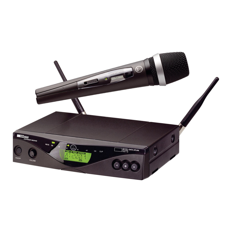
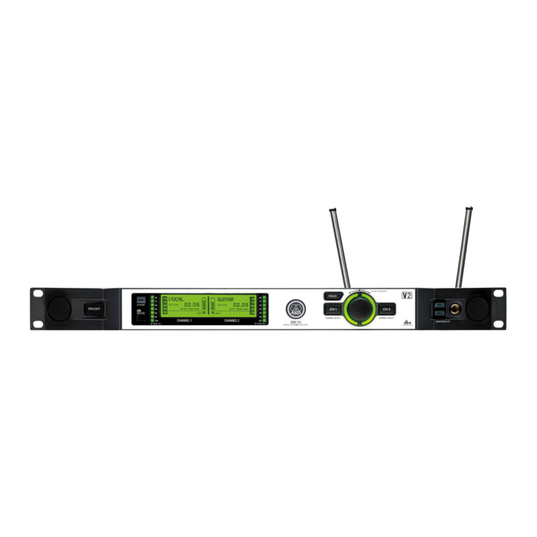
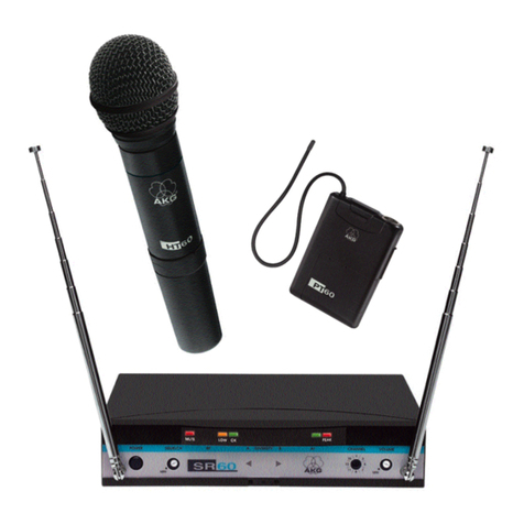
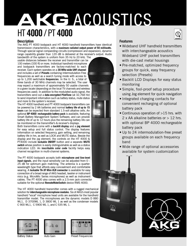
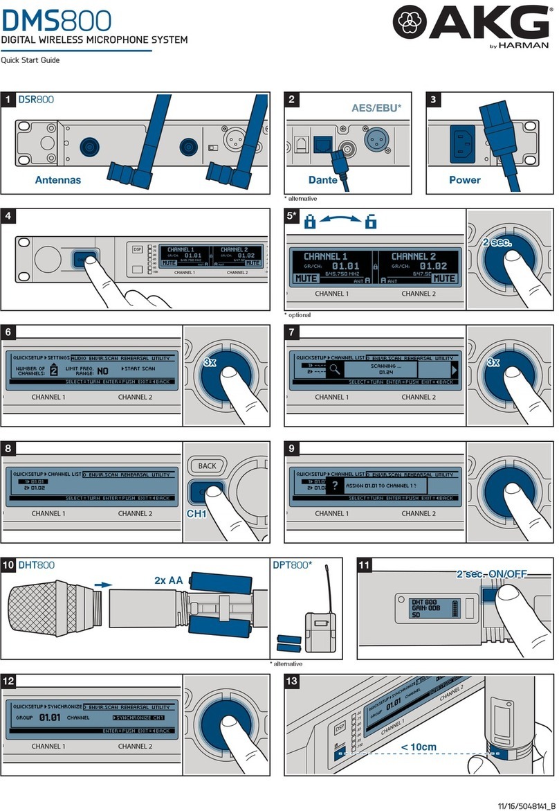
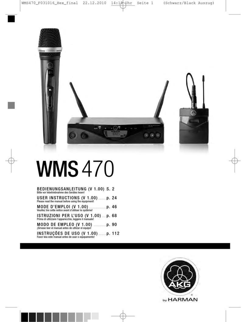
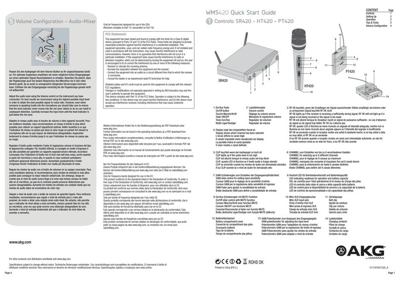
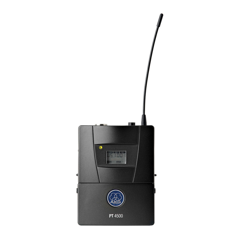
AKG WMS 450 - SERVICE User manual

WMS 450
Multichannel System
Schematic&PartList
1-12 Channel
WolfgangFritz /Feb. 2008
MCS0802001
1

Introduction
SRA2 B/W activedirectionalantenna
For Venues (tour sound&installs) thatcover largedistances (up to150m, 500 ft) like
music halls,stadiums and other openair applications.
RA4000B/W active omni-directional antenna
For Venues withouta designated transmitter area and up to 100m/330 ft freelineof
sight. Ideal for conference rooms, multi purpose halls, housesofworship etc.
Thefollowingschematics willhelpyou toeasily setup multichannelsystems.
Please use the equipmentthat isspecifiedin the schematicsonly.
For yourconvenience andunderstanding, we’veadded technicalinformation andpartlists.
You can usethis part lists whenordering thesystem you require! If you need any help
regardingthefrequencyregulationsorifyourparticularsituation doesn’tallowfora standard
All the WMS450 Systems in thisdocument aredesigned withactive antennasthatcan
used in all venueswith a 20mRG58 antenna cable.
WolfgangFritz /Feb. 2008
MCS0802001
2

Content
WolfgangFritz /Feb. 2008
MCS0802001
General InformationPage
Receiver/AntennaPlacement Information4
Squelch Information4
Intermodulation Information4
CableAttenuation Information5
PS4000dipswitch Information5
AB4000dipswitch Information5
PS4000dipSwitchMatrix Information6
RequiredComponentMatrix Information7
Glossar Information8
WMS SystemAntennaTypePage
SRA2B/W
RA4000B/W
SRA2B/W
RA4000B/W
2Channelno PS4000
2Channelno PS4000
1Channel
Channel1
2 2ChannelRA4000B/W
SRA2B/WChannel
SRA2B/W4 4Channelno PSU4000
Channelno PSU4000RA4000B/W
4
4
5
5
Channel
Channel
Channel
Channel
SRA2B/W
RA4000B/W
SRA2B/W
RA4000B/W
SRA2B/W
6ChannelRA4000B/W
6Channel
8ChannelSRA2B/W
8ChannelRA4000B/W
Channel9 9Channel
10Channel
10Channel
SRA2B/W
RA4000B/W
SRA2B/W
RA4000B/W
SRA2B/W
RA4000B/W
12
12 Channel
Channel
Schematic/ Part List
9
11
13
15
17
19
21
23
25
27
29
31
33
35
37
39
41
43
45
47
49
51
3

TechnicalInformation
Wireless Basics
Everywireless microphone systemhas tooperateon one specific frequency
Transmitter and receiver ofa system need to workonthe same frequency
Two transmitters cannot beused with onereceiver at the same time
Receiver/Antenna Placement
Directline of sightbetweentransmitter and receiver antenna
Place the receiver/antennas atleast5 ft. (1.5 m) away fromall transmitters
Place the receiver antennas at least5ft. (1.5 m) away from any big metal object,
wire(particularly wire mesh) orsheet metalstructures, walls,ceilings, etc.
Donot placetheantennasinhidden places (behind walls)
Place the receiver at least 5ft. (1.5 m) awayfrom any equipmentthat may emitRF
radiation such as lightingracks, fluorescentlamps, digital effect units, orPCs
Squelch
Standard: Carrier squelch, manual
– Operates strictlyonthe signal strengthof the signal.
– If received signal strengthdrops under the adjustablesquelch threshold the
audio output ismuted
Advanced: ToneCode (only WMS4000)
– The audio turnson onlyinthepresenceof the correct tonecode and an
adequate signal strength (-100dbm)
–Lock out all signals except ones withthecorrectkey.
Intermodulation
Intermodulationis the result of two or moresignalsofdifferent frequencies being
mixed together, forming additionalsignalsthat arenot harmonic frequenciesof
either.
Byusing morethanone transmitter simultaneously at the same location,intermodulation
happens in thereceiverand/or transmitter. In your case thisintermodulationproducts
aregenerated inthe bandwidththatyouareusing.
Toavoid intermodulating frequencies,we offer you pre-calculated frequenciesaspresets in
the SR450 and SR4000Receiver. Please, makesure that when setting up a multi channel
system, all your receivers are set to the same countrypreset (NAME)and group.Use the
Automaticchannelfunction(autosetup) to scan for free frequencies at your venue.
Wolfgang Fritz/ Feb. 2008
MCS0802001
4

RG58 Cable Attenuation (MKPS, MKA5, MKA20 antenna cable)
Cable Attenuation
Toobtain the bestsound possible, you need tohave the rightRFinput level throughout
your signal chain. Premiumqualitywireless systems like the WMS450 and WMS4000,
offer you adjustable RF-level settings that garantee to maximise operatingdistance even
when using different cable lenghts and different types ofcable! For this purpose,AKG’s
PS4000Wantenna splitter,has 3 dip switches that you’ll find ontherightside ofit’s
front panel, behindtheAKG logo.
PS4000 dip switch
ThisdipswitchreducetheinputRF levelofthe PS4000 between0dB and14 dB.
Allantenna outputleveland the cascade(link) output level have an effect on this reduction.
AB4000dipswitch
The AB4000 has a fix 17.5dB amplifier in the output stage.The dip switch reduce the
inputRFlevel oftheAB4000 between0dBand -14 dB. AB4000 get the DC power
through the antenna cable from the PS4000or an ASU4000unit.
Rear View
4x Antenna A output
(DC power)
Antenna A input Ant. B
Antenna Acascade output
(DC power)
dipswitches behind AKG Logo
Signal level adjustment
Attenuation
PS4000W – PowerSplitter
AB4000 – Antenna Booster
Wolfgang Fritz/ Feb. 2008
MCS0802001
Signal leveladjustment
Internal
Attenuation Total Gain
3.5dB
5.5dB
7.5dB
9.5dB
11.5 dB
13.5 dB
15.5 dB
17.5 dB
5

3x MKA 20
60m/198ft
AntennaBooster
AB4000
necessary !
4x MKA 20
80m/264ft
AntennaBooster
AB4000
necessary !
MKA 5
5m/16ft
MKA 20
20m/ 66ft
MKA 5 + MKA 20
25m/ 82ft
2x MKA 20
40m/132ft
Cable type
&
Length
0110E0189
1m/ 3ft
PS4000 dipswitchmatrix (RG58 cable)
RA4000 WSRA2 W RA4000 BWSRA2 BW
Passiv Antennas Active Antennas
Antenna type
&
Gain
0 dB
0 dB 0 dB -4dB
0 dB -2dB -14 dB
-8dB -12 dB
-6dB -10 dB
0 dB
0dB -2 dB
RA4000BW
2xMKA20
AB4000
0dB
PS4000
-4dB
1xMKA20
SRA2 BW
2xMKA20
AB4000
0 dB
PS4000
-8 dB
1xMKA20
RA4000BW
2xMKA20
AB4000
0dB
PS4000
0dB
2xMKA20
SRA2 BW
2xMKA20
AB4000
0 dB
PS4000
0 dB
2xMKA20
1 dB4-6dB18 dB22-24 dB
¼wave
UHF Antenna
Youhaveto use thisPS4000 dipswitch settings at all PS4000 withdirect connection
totheantennas.
All cascade PS4000 havethe same dip switchsetting ON/ON/ON (0dB)
WolfgangFritz /Feb. 2008
MCS0802001
6

Number of …
PS4000ZAPD-21MKPSPSU4000
AC12 Power
SupplyPSU01/4000
AC12Power
SupplyHUB4000Q
21040+31+01
31060+41+01
41081+01+01
510101+01+11
620141+02+01
720161+02+01
820181+02+01
920201+02+12
1030241+03+02
1130261+03+02
1230281+03+02
1330301+13+12
1442362+04+02
1542382+04+02
1642402+04+02
1742422+04+13
1842442+04+23
1952522+05+03
2052542+05+03
2152562+05+13
2252582+05+23
2362622+06+03
2462642+06+03
2562662+16+14
2662682+26+24
3290803+09+04
3690883+49+45
481301205+013+06
521301285+213+46
Additional you will need min.2xantennasand2xMKAxxantennacables!
Please, lookatthe"PS4000dipswitchmatrix(RG58)" to findyour antennacomponents.
PSU01/4000 isa12V/2APower SupplyAdapter (1xPSU4000=3xPSU01/4000)
WMS
Receiver
Standard Power Supply !onlyavailableinUS!
Power Supply
WolfgangFritz /Feb. 2008
MCS0802001
WMS450/4000 ComponentMatrix
7

Glossar
SR4000 –WMS4000 Stationary Receiver
PS4000W –Power Splitter 1:4(Distribute RFsignal and DCPower)
Splits1 antenna to 4 receiver
Antenna cascade(Link) output to send RF-Signalto next PS4000.
Cascademax. 3 PS4000.
If you needmore than 12 channels use an ZAPD infrontof the first PS4000.
PSU4000 – PowerSupply Unit with 3x 12 voltoutputs (2.5A and2A)
SRA2 B/W –Active Directional Antenna(21dB Gain)
RA4000 B/W –Active Omni-directionalAntenna (18dB Gain)
HPA4000 –HeadphoneAmplifier(8x stereo jack inputs, 1HP output)
CU400 – ChargingUnitfor WMS400/450(2 transmitter / unit)
ZAPD-21 –PassiveCombiner2:1 and 1:2
MKPS – 0.65m/2feetRG58 antenna cable
MKA20 –20/66ft RG58 antennacable
ASU4000 – AntennaSupplyUnit
Supplies up tothree active elements(RA4000BW, SRA2BW,AB4000)
0110E01890 – Frontassemblycable
Install ¼ wave antennas atthe front ofthe rack
AB4000 –Antenna Booster
3.5 dB – 17.5 dB amplifier
Front assembly cable & ¼ wave antenna
Wolfgang Fritz/ Feb. 2008
MCS0802001
Cable
MKA5 – 5m/16ft RG58antennacable
SR4000
XLR
AUDIO OUT
ANT A IN
DC IN (12V/0.5A) ¼“ TS
AUDIOOUT
ANTB IN
Mixer
DATA
LOGIC OUT
1A
1B
2A
2B
3A
3B
4B
4A
ANTAINANTB IN
DC IN (12V/0.5A)
PS4000W
CASCADE A
CASCADE B
DC OUT1 (2.5A)
AC POWER
PSU4000
DC OUT 2 (2A)
DC OUT 3 (2A)
~90-230V
SRA2B/W
ANTOUT
RA4000 B/W
ANTOUT
HPA4000
DCIN(12V/0.5A)Headphone
SR1
SR2
SR3
SR4
SR5
SR6
SR8
SR7
CU4000
DC IN (12V/1.4A)
ZAPD-21
A
S
B
ASU4000
ANT OUT
ANT IN
DC IN(12V/0.5A)
AB4000
ANTOUT
ANTIN
HUB4000Q
DCIN(12V/0.5A)ETHERNET
DEV1
DEV2
DEV3
DEV4
DEV5
DEV6
DEV8
DEV7
HUB4000Q – Network Concentratorfor 8devices (SR4000 or SST4)
Operate with Harman „System Architect“ software - http://hiqnet.harmanpro.com
8

2 HT450orPT450charging system(optional)
Project
Designer
Date Revision
1channel WMS450 system
(SRA2 B/W – Antennas)
Wolfgang Fritz
02.02.2008 1.0
Build document1.0
Ref.No. MCS0802001
K171Studio Headphone
Headphone amplifier (optional)
1 ChannelWMS450 System
With directional antennas &40m antennacable (132feet)
HPA4000
DC IN(12V/0.5A)Headphone
SR1
SR2
SR3
SR4
SR5
SR6
SR8
SR7
5V Power Supply(1.4 A)
CU400
DC IN (5V/1.4A)
AC12 Power Supply (500mA)
ASU4000
ANTOUT
ANTIN
DC IN(12V/0.5A)
AC12Power Supply (500mA) ASU4000
ANT OUT
ANTIN
DC IN (12V/0.5A)
AC12 PowerSupply(500mA)
2xMKPS
BNCI-connector
Available e.g. www.rs-components.com,
Ordernumber 112-1798
BNC I-connector
Available e.g. www.rs-components.com,
Ordernumber 112-1798
2x MKA20
(BNCI-connector is necessary tolink cables!)
2x MKA20
(BNC I-connector is necessaryto link cables!)
SRA2B/W
ANTOUT
SRA2B/W
ANT OUT
SR450
XLR
AUDIO OUT
ANTA IN
DC IN (12V/0.5A) ¼“TS
AUDIO OUT
ANTB IN
Mixer
9

Wolfgang Fritz /Feb.2008
MCS0802001
Multichannel Systemswith externalantennas
unitsdescriptioncommentcode
1
73
PT450or HT450transmitter; SR450receiver, withAC adapter, rackmount kit, mic holder,
batteries, user'smanual; carrying case 3235X....
3236X....
3237X....
3238X....
3239X....
2
72
External directional active"paddle" antennawithamplifier (2req.)3009Z0001
2
54
Connectingcable for PS toSR2.15ft (65cm)6000H0206
4
55
66ft. (20m)Cablesfor connectingext. antennastomulti-couplers (2req.)KOAXRG586000H0205
2
10
AntennaSupplyunit forlong antennacables (BNC connector) without AC-Adapter3009Z0010
2
4
12V AC-Adapterfor1PS4000, ASU4000, HUB 4000, HPA4000 orSR4000.7801H000…
2BNC I-connector
EXTERNAL!! Not availableatAKG
-BNCI-Connector
(youcanbuy it at www.rs-components.com, Ordernumber112-1798)
unitsdescriptioncommentcode
1
35
Chargingunit forWMS400transmitters,ACadaptersincluded2934Z000…
1
45
Headphonemonitoringamplifier-8 receivers ins; & selectable out without ACAdapter2998Z0004
1
85
Closed-back circum-aural dynamic stereoheadphone, mini XLR connector, detachable cable2908Z0001
1
4
12V AC-Adapterfor1PS4000, ASU4000, HUB 4000, HPA4000 orSR4000.7801H000…
1Channel WMS450Systemwithdirectionalantennas,no PSU4000,no PS4000
Optional Components(Charging System &Headphone Amplifier)
CU400
SRA2 B/W
WMS450
MK PS
MKA20
HPA4000/ none
K171 Studio
AC12
ASU 4000 (BNC/none)
AC12
10

2 HT450orPT450charging system(optional)
Project
Designer
Date Revision
1channel WMS450 system
(RA4000B/W – Antennas)
Wolfgang Fritz
02.02.2008 1.0
Build document1.0
Ref.No. MCS0802001
K171Studio Headphone
Headphone amplifier (optional)
1 ChannelWMS450 System
withomni-directional antennas & 25mantenna cable(82feet)
HPA4000
DC IN(12V/0.5A)Headphone
SR1
SR2
SR3
SR4
SR5
SR6
SR8
SR7
5V Power Supply(1.4 A)
CU400
DC IN (5V/1.4A)
AC12 Power Supply (500mA)
RA4000B/W
ANTOUT
RA4000B/W
ANT OUT
ASU4000
ANTOUT
ANTIN
DC IN(12V/0.5A)
AC12Power Supply (500mA) ASU4000
ANT OUT
ANTIN
DC IN (12V/0.5A)
AC12 PowerSupply(500mA)
2xMKPS
BNCI-connector
Available e.g. www.rs-components.com,
Ordernumber 112-1798
BNC I-connector
Available e.g. www.rs-components.com,
Ordernumber 112-1798
1x MKA20 + 1x MKA5
(BNCI-connector is necessary tolink cables!)
1x MKA20 + 1x MKA5
(BNC I-connector is necessaryto link cables!)
SR450
XLR
AUDIO OUT
ANTA IN
DC IN (12V/0.5A) ¼“TS
AUDIO OUT
ANTB IN
Mixer
11

Multichannel Systemswith externalantennas
unitsdescriptioncommentcode
1
73
PT450or HT450transmitter; SR450receiver, withAC adapter, rackmount kit, mic holder,
batteries, user'smanual; carrying case 3235X....
3236X....
3237X....
3238X....
3239X....
2
66
External omni-directional activedipoleantennawithamplifier (2 req.)2632Z0030
2
54
Connectingcable for PS toSR2.15ft (65cm)6000H0206
4
55
66ft. (20m)Cablesfor connectingext. antennastomulti-couplers (2req.)KOAXRG586000H0205
2
10
AntennaSupplyunit forlong antennacables (BNC connector) without AC-Adapter3009Z0010
2
4
12V AC-Adapterfor1PS4000, ASU4000, HUB 4000, HPA4000 orSR4000.7801H000…
2BNC I-connector
EXTERNAL!! Not availableatAKG
-BNCI-Connector
(youcanbuy it at www.rs-components.com, Ordernumber112-1798)
unitsdescriptioncommentcode
1
35
Chargingunit forWMS400transmitters,ACadaptersincluded2934Z000…
1
45
Headphonemonitoringamplifier-8 receivers ins; & selectable out without ACAdapter2998Z0004
1
85
Closed-back circum-aural dynamic stereoheadphone, mini XLR connector, detachable cable2908Z0001
1
4
12V AC-Adapterfor1PS4000, ASU4000, HUB 4000, HPA4000 orSR4000.7801H000…
1ChannelWMS450System withomni-directionalantennas,no PSU4000,no PS4000
Optional Components(Charging System &Headphone Amplifier)
CU400
RA4000 B/W
WMS450
MK PS
MKA20
HPA4000/ none
K171 Studio
AC12
ASU 4000 (BNC/none)
AC12
Wolfgang Fritz /Feb.2008
MCS0802001
12

2 HT450orPT450charging system(optional)
Project
Designer
Date Revision
2channel WMS450 system
(SRA2 B/W – Antennas,no PS4000, PSU4000)
Wolfgang Fritz
02.02.2008 1.0
Build document1.0
Ref.No. MCS0802001
4xMKPS
K171 StudioHeadphone
Headphoneamplifier (optional)
2 ChannelWMS450 System
With directional antennas &40m antennacable (132feet)
HPA4000
DC IN (12V/0.5A)Headphone
SR1
SR2
SR3
SR4
SR5
SR6
SR8
SR7
5V Power Supply(1.4 A)
CU400
DC IN (5V/1.4A)
AC12 Power Supply (500mA)AC12PowerSupply(500mA)
AC12PowerSupply(500mA)
ZAPD-21
A
S
B
ZAPD-21
A
S
B
ASU4000
ANTOUT
ANTIN
DC IN(12V/0.5A)
AC12Power Supply (500mA) ASU4000
ANT OUT
ANTIN
DC IN (12V/0.5A)
AC12 PowerSupply(500mA)
2xMKPS
BNCI-connector
Available e.g. www.rs-components.com,
Ordernumber 112-1798
BNC I-connector
Available e.g. www.rs-components.com,
Ordernumber 112-1798
2x MKA20
(BNCI-connector is necessary tolink cables!)
2x MKA20
(BNC I-connector is necessaryto link cables!)
SRA2B/W
ANTOUT
SRA2B/W
ANT OUT
SR450
XLR
AUDIO OUT
ANTA IN
DC IN (12V/0.5A) ¼“ TS
AUDIOOUT
ANTB IN
Mixer
SR450
XLR
AUDIO OUT
ANT A IN
DC IN(12V/0.5A) ¼“ TS
AUDIO OUT
ANTB IN
Mixer
13

MultichannelSystemswithexternalantennas
unitsdescriptioncommentcode
2
73
PT450orHT450transmitter; SR 450receiver, withACadapter, rack mount kit, micholder,
batteries, user's manual; carryingcase 3235X....
3236X....
3237X....
3238X....
3239X....
2
72
External directionalactive "paddle" antenna withamplifier (2 req.)3009Z0001
6
54
ConnectingcableforPStoSR2.15ft (65cm)6000H0206
4
55
66ft. (20m)Cables forconnecting ext. antennas tomulti-couplers (2 req.)KOAXRG586000H0205
2
10
AntennaSupply unit for longantennacables(BNCconnector) without AC-Adapter3009Z0010
2
4
12V AC-Adapter for 1PS 4000, ASU4000, HUB4000, HPA 4000or SR4000.7801H000…
2
88
passivepowercombiner(2in 1out)or Splitter (1in 2out)SERVSON76
2BNC I-connector
EXTERNAL!! Not availableatAKG
-BNCI-Connector
(you canbuyit at www.rs-components.com, Ordernumber112-1798)
unitsdescriptioncommentcode
1
35
Chargingunit for WMS 400 transmitters, ACadapters included2934Z000…
1
45
Headphonemonitoringamplifier-8 receivers ins; &selectableout without ACAdapter2998Z0004
1
85
Closed-back circum-aural dynamic stereo headphone, mini XLRconnector, detachable cable2908Z0001
1
4
12V AC-Adapter for 1PS 4000, ASU4000, HUB4000, HPA 4000or SR4000.7801H000…
2ChannelWMS450System withdirectionalantennas,no PSU4000, no PS4000
OptionalComponents(ChargingSystem&Headphone Amplifier)
CU400
SRA2 B/W
WMS450
MK PS
MKA20
HPA4000/ none
K171 Studio
AC12
ASU 4000 (BNC/none)
AC12
ZAPD21
Wolfgang Fritz /Feb.2008
MCS0802001
14

2 HT450orPT450charging system(optional)
Project
Designer
Date Revision
2channel WMS450 system
(RA4000B/W – Antennas, no PS4000,PSU4000)
Wolfgang Fritz
02.02.2008 1.0
Build document1.0
Ref.No. MCS0802001
4xMKPS
K171 StudioHeadphone
Headphoneamplifier (optional)
2 ChannelWMS450 System
withomni-directional antennas & 25mantenna cable(82feet)
HPA4000
DC IN (12V/0.5A)Headphone
SR1
SR2
SR3
SR4
SR5
SR6
SR8
SR7
5V Power Supply(1.4 A)
CU400
DC IN (5V/1.4A)
AC12 Power Supply (500mA)AC12PowerSupply(500mA)
AC12PowerSupply(500mA)
RA4000B/W
ANTOUT
RA4000B/W
ANT OUT
ZAPD-21
A
S
B
ZAPD-21
A
S
B
ASU4000
ANTOUT
ANTIN
DC IN(12V/0.5A)
AC12Power Supply (500mA) ASU4000
ANT OUT
ANTIN
DC IN (12V/0.5A)
AC12 PowerSupply(500mA)
2xMKPS
BNCI-connector
Available e.g. www.rs-components.com,
Ordernumber 112-1798
BNC I-connector
Available e.g. www.rs-components.com,
Ordernumber 112-1798
1x MKA20 + 1x MKA5
(BNCI-connector is necessary tolink cables!)
1x MKA20 + 1x MKA5
(BNC I-connector is necessaryto link cables!)
SR450
XLR
AUDIO OUT
ANTA IN
DC IN (12V/0.5A) ¼“ TS
AUDIOOUT
ANTB IN
Mixer
SR450
XLR
AUDIO OUT
ANT A IN
DC IN(12V/0.5A) ¼“ TS
AUDIO OUT
ANTB IN
Mixer
15

Multichannel Systemswith externalantennas
unitsdescriptioncommentcode
2
73
PT450or HT450transmitter; SR450receiver, withAC adapter, rackmount kit, mic holder,
batteries, user'smanual; carrying case 3235X....
3236X....
3237X....
3238X....
3239X....
2
66
External omni-directional activedipoleantennawithamplifier (2 req.)2632Z0030
6
54
Connectingcable for PS toSR2.15ft (65cm)6000H0206
2
55
66ft. (20m)Cablesfor connectingext. antennastomulti-couplers (2req.)KOAXRG586000H0205
2
56
16.5ft. (5m)Cables for connectingext. antennas tomulti-couplers (2req.)KOAXRG582455Z0062
2
10
AntennaSupplyunit forlong antennacables (BNC connector) without AC-Adapter3009Z0010
2
4
12V AC-Adapterfor1PS4000, ASU4000, HUB 4000, HPA4000 orSR4000.7801H000…
2
88
passivepower combiner (2in1out)orSplitter(1in2out)SERVSON76
2BNC I-connector
EXTERNAL!! Not availableatAKG
-BNCI-Connector
(youcanbuy it at www.rs-components.com, Ordernumber112-1798)
unitsdescriptioncommentcode
1
35
Chargingunit forWMS400transmitters,ACadaptersincluded2934Z000…
1
45
Headphonemonitoringamplifier-8 receivers ins; & selectable out without ACAdapter2998Z0004
1
85
Closed-back circum-aural dynamic stereoheadphone, mini XLR connector, detachable cable2908Z0001
1
4
12V AC-Adapterfor1PS4000, ASU4000, HUB 4000, HPA4000 orSR4000.7801H000…
Optional Components(Charging System &Headphone Amplifier)
2ChannelWMS450System withomni-directionalantennas,no PSU4000,no PS4000
CU400
RA4000 B/W
WMS450
MK PS
MKA20
HPA4000/ none
K171 Studio
AC12
ASU 4000 (BNC/none)
AC12
ZAPD21
MKA5
Wolfgang Fritz /Feb.2008
MCS0802001
16

2 HT450orPT450charging system(optional)
Project
Designer
Date Revision
2channel WMS450 system
(SRA2 B/W – Antennas, no PSU4000)
Wolfgang Fritz
02.02.2008 1.0
Build document1.0
Ref.No. MCS0802001
MKA20MKA20
4xMKPS
K171 StudioHeadphone
Headphoneamplifier (optional)
2 ChannelWMS450 System
with directional antennas&20(40)m antennacable (66 or 132 feet)
up
down
-12dB
2xMKA20
(40mCable)
-2dB
1xMKA20
(20m Cable)
40m/132 ft Version:
2x MKA20
BNC I-connector is necessary to link cables!
Available e.g.www.rs-components.com,
Ordernumber 112-1798
Rear View
4xAntenna Aoutput
(DC power)
Antenna Ainput Ant.B
Antenna Acascade output
(DC power)
dipswitches behind AKG Logo
Signal level adjustment
Attenuation
PS4000W – Power Splitter
1A
1B
2A
2B
3A
3B
4B
4A
ANTA INANTB IN
DC IN (12V/0.5A)
PS4000W
CASCADEA
CASCADEB
HPA4000
DC IN (12V/0.5A)Headphone
SR1
SR2
SR3
SR4
SR5
SR6
SR8
SR7
5V Power Supply(1.4 A)
CU400
DC IN (5V/1.4A)
SRA2 B/W
ANT OUT
SRA2B/W
ANT OUT
AC12PowerSupply(500mA)
AC-CU4000PowerSupply (1.4A) (recommend) or
AC12 Power Supply (500mA)
AC12PowerSupply(500mA)
SR450
XLR
AUDIO OUT
ANTA IN
DC IN (12V/0.5A) ¼“ TS
AUDIO OUT
ANTBIN
Mixer
SR450
XLR
AUDIO OUT
ANTA IN
DC IN (12V/0.5A) ¼“ TS
AUDIO OUT
ANTBIN
Mixer
17

Multichannel Systemswith externalantennas
unitsdescriptioncommentcode
2
73
PT450or HT450transmitter; SR450receiver, withAC adapter, rackmount kit, mic holder,
batteries, user'smanual; carrying case 3235X....
3236X....
3237X....
3238X....
3239X....
1
59
Wide bandantenna multicoupler(4+1out)without AC-Adapter2996Z0008
2
72
External directional active"paddle" antennawithamplifier (2req.)3009Z0001
4
54
Connectingcable for PS toSR2.15ft (65cm)6000H0206
2
55
66ft. (20m)Cablesfor connectingext. antennastomulti-couplers (2req.)KOAXRG586000H0205
1
7
12V AC-Adapter(EU-Version)power supplyCU4000, PS 40007801H000…
2
55
66ft. (20m)Cablesfor connectingext. antennastomulti-couplers (2req.)KOAXRG586000H0205
2BNC I-connector
EXTERNAL!! Not availableatAKG
-BNCI-Connector
(youcanbuy it at www.rs-components.com, Ordernumber112-1798)
unitsdescriptioncommentcode
1
35
Chargingunit forWMS400transmitters,ACadaptersincluded2934Z000…
1
45
Headphonemonitoringamplifier-8 receivers ins; & selectable out without ACAdapter2998Z0004
1
85
Closed-back circum-aural dynamic stereoheadphone, mini XLR connector, detachable cable2908Z0001
1
4
12V AC-Adapterfor1PS4000, ASU4000, HUB 4000, HPA4000 orSR4000.7801H000…
2ChannelWMS450Systemwithdirectionalantennas,PSU4000
Optional Components(Charging System &Headphone Amplifier)
Additional partsfor 40m(132feet) AntennaCable
CU400
SRA2 B/W
WMS450
PS 4000W
MK PS
MKA20
HPA4000/ none
K171 Studio
AC12
AC-CU4000
MKA20
Wolfgang Fritz /Feb.2008
MCS0802001
18

2 HT450orPT450charging system(optional)
Project
Designer
Date Revision
2channel WMS450 system
(RA4000B/W – Antennas, no PSU4000)
Wolfgang Fritz
02.02.2008 1.0
Build document1.0
Ref.No. MCS0802001
MKA20MKA20
8xMKPS
K171 StudioHeadphone
Headphoneamplifier (optional)
2 ChannelWMS450 System
withomni-directionalantennas & 20(40)m antenna cable (66 or 132 feet)
up
down
-8dB
2xMKA20
(40mCable)
0dB
1xMKA20
(20m Cable)
40m/132 ft Version:
2x MKA20
BNC I-connector is necessary to link cables!
Available e.g.www.rs-components.com,
Ordernumber 112-1798
Rear View
4xAntenna Aoutput
(DC power)
Antenna Ainput Ant.B
Antenna Acascade output
(DC power)
dipswitches behind AKG Logo
Signal level adjustment
Attenuation
PS4000W – Power Splitter
1A
1B
2A
2B
3A
3B
4B
4A
ANTA INANTB IN
DC IN (12V/0.5A)
PS4000W
CASCADEA
CASCADEB
HPA4000
DC IN (12V/0.5A)Headphone
SR1
SR2
SR3
SR4
SR5
SR6
SR8
SR7
5V Power Supply(1.4 A)
CU400
DC IN (5V/1.4A)
AC12PowerSupply(500mA)
RA4000B/W
ANTOUT
RA4000B/W
ANTOUT
AC-CU4000PowerSupply (1.4A) (recommend) or
AC12 Power Supply (500mA)
SR450
XLR
AUDIO OUT
ANTA IN
DC IN (12V/0.5A) ¼“ TS
AUDIO OUT
ANTBIN
Mixer
SR450
XLR
AUDIO OUT
ANTA IN
DC IN (12V/0.5A) ¼“ TS
AUDIO OUT
ANTBIN
Mixer
19

Multichannel Systemswith externalantennas
unitsdescriptioncommentcode
2
73
PT450or HT450transmitter; SR450receiver, withAC adapter, rackmount kit, mic holder,
batteries, user'smanual; carrying case 3235X....
3236X....
3237X....
3238X....
3239X....
1
59
Wide bandantenna multicoupler(4+1out)without AC-Adapter2996Z0008
2
66
External omni-directional activedipoleantennawithamplifier (2 req.)2632Z0030
4
54
Connectingcable for PS toSR2.15ft (65cm)6000H0206
2
55
66ft. (20m)Cablesfor connectingext. antennastomulti-couplers (2req.)KOAXRG586000H0205
1
7
12V AC-Adapter(EU-Version)power supplyCU4000, PS 40007801H000…
2
55
66ft. (20m)Cablesfor connectingext. antennastomulti-couplers (2req.)KOAXRG586000H0205
2BNC I-connector
EXTERNAL!! Not availableatAKG
-BNCI-Connector
(youcanbuy it at www.rs-components.com, Ordernumber112-1798)
unitsdescriptioncommentcode
1
35
Chargingunit forWMS400transmitters,ACadaptersincluded2934Z000…
1
45
Headphonemonitoringamplifier-8 receivers ins; & selectable out without ACAdapter2998Z0004
1
85
Closed-back circum-aural dynamic stereoheadphone, mini XLR connector, detachable cable2908Z0001
1
4
12V AC-Adapterfor1PS4000, ASU4000, HUB 4000, HPA4000 orSR4000.7801H000…
2ChannelWMS450Systemwithomni-directionalantennas,no PSU4000
Optional Components(Charging System &Headphone Amplifier)
Additional partsfor 40m(132feet) AntennaCable
CU400
RA4000 B/W
WMS450
PS 4000W
MK PS
MKA20
HPA4000/ none
K171 Studio
AC12
AC-CU4000
MKA20
Wolfgang Fritz /Feb.2008
MCS0802001
20
Other manuals for WMS 450 - SERVICE
3
Table of contents
Other AKG Microphone System manuals
Popular Microphone System manuals by other brands

Samson
Samson SYNTH32 owner's manual

PCB Piezotronics
PCB Piezotronics 377 Series Installation and operating manual

reIDEA Technology
reIDEA Technology bPoint COMFORT quick start guide

VocoPro
VocoPro VHF-3000 owner's manual

Pyle Pro
Pyle Pro PDWM4650 user manual

2000'S Audio
2000'S Audio AKJ780C owner's manual