2.1 Einleitung
Wichtig!
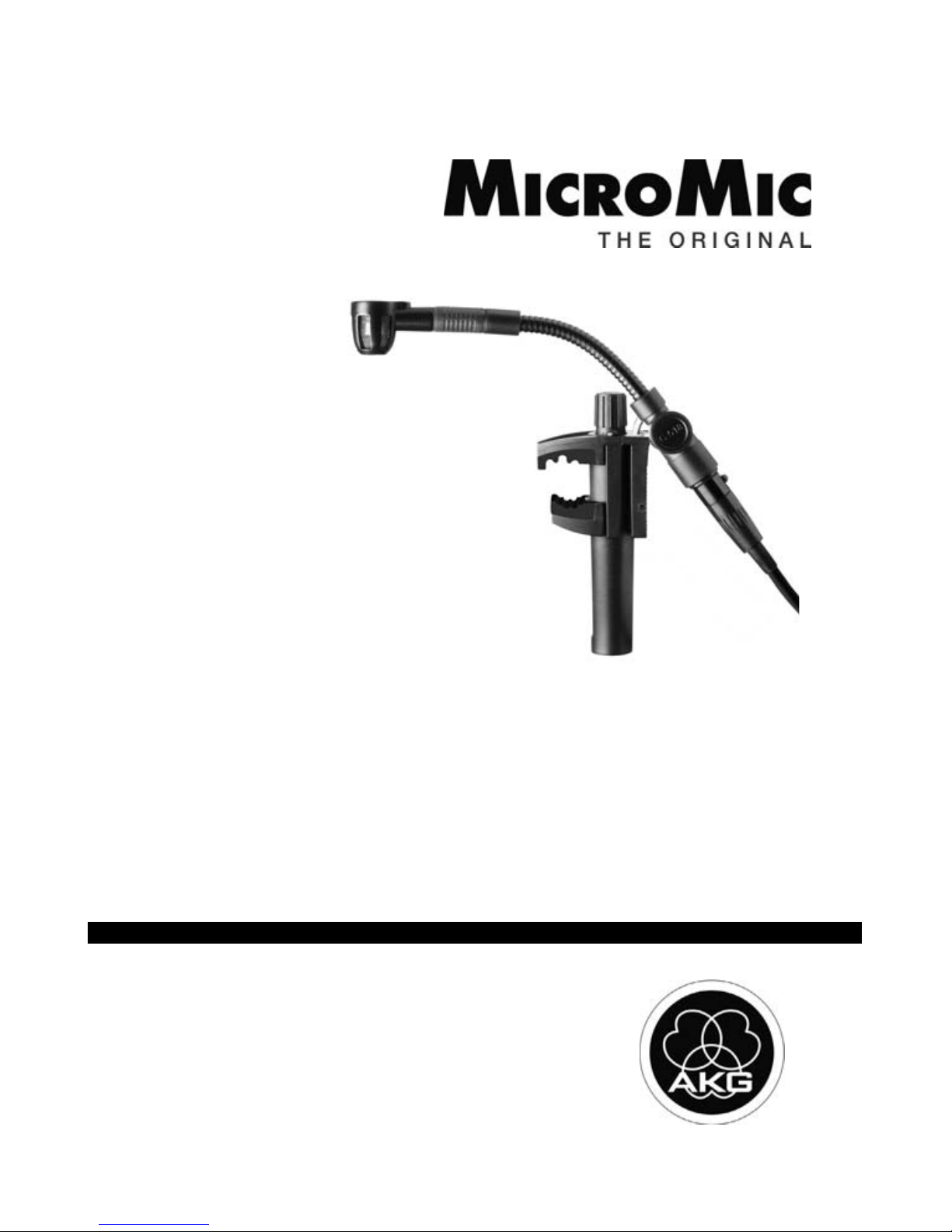
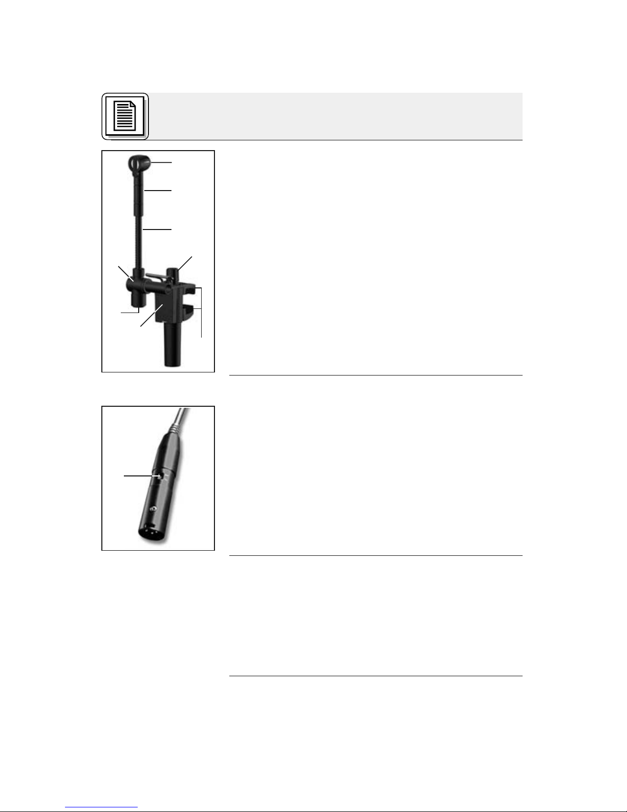
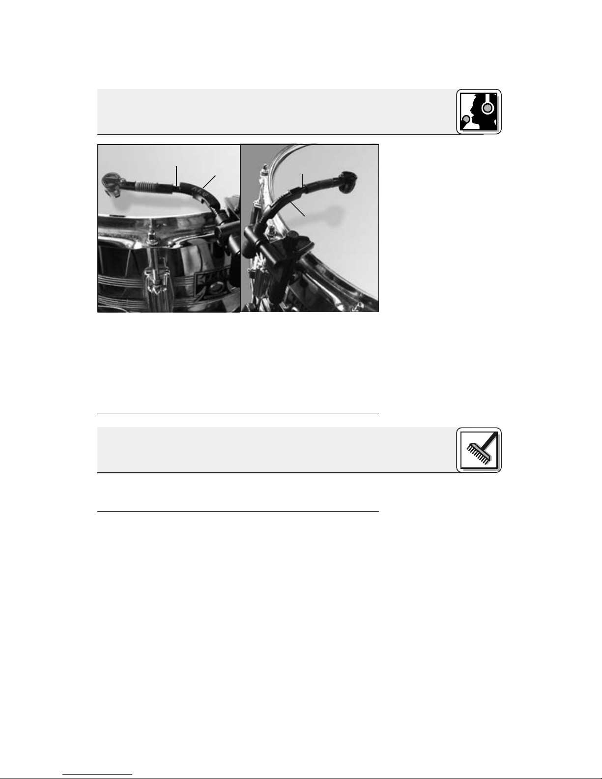
2.2C518M
Siehe Abb. 1 auf
Seite 4.
2.3C518ML
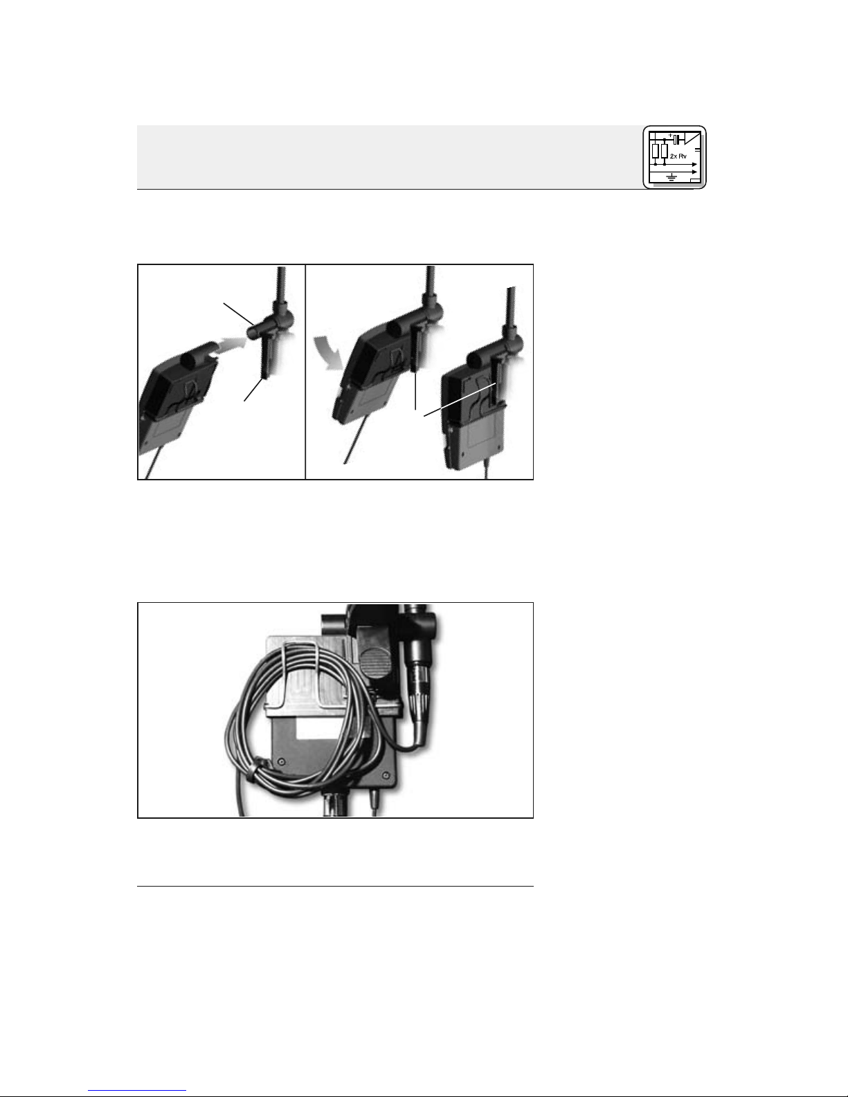
2.3.1 B 29 L oder
MPA V L
Kabel abziehen:
Wichtig!
Das C 518 M/C 518 ML ist ein Kondensatormikro-
fon und benötigt daher eine Stromversorgung.
Wenn Sie andere als die von AKG empfohlenen
Speisegeräte verwenden, kann das Mikrofon
beschädigt werden und erlischt die Garantie.
1. Verbinden Sie mittels des mitgelieferten An-
schlusskabels die Ausgangsbuchse (5)am
Schwanenhals mit einem symmetrischen XLR-
Mikrofoneingang mit Phantomspeisung.
2. Schalten Sie die Phantomspeisung ein. (Lesen
Sie dazu in der Betriebsanleitung des jeweili-
gen Gerätes nach.)
1. Verbinden Sie mittels des mitgelieferten An-
schlusskabels die Ausgangsbuchse (5)am
Schwanenhals mit einer der beiden Mini-XLR-
Buchsen am B 29 L oder der Mini-XLR-Kupp-
lung am Anschlusskabel des MPA V L.
Der Stecker verriegelt sich automatisch.
•Zum Abziehen des Kabels drücken Sie auf den
Entriegelungsknopf am Mini XLR-Stecker und
ziehen Sie den Stecker aus der Buchse heraus.
•Umdas Kabelnichtzubeschädigen,zie-
henSieniemals am Kabelselbst!
2. B29L:Verbinden Sie das B 29 L mit dem ge-
wünschten Eingang.
MPA V L: Stecken Sie den MPA V L an einen
symmetrischen XLR-Mikrofoneingang mit
Phantomspeisung an und schalten Sie die
Phantomspeisung ein.
5
AKG C 518 M / C 518 ML
2 Anschluss