AKO 15640 User manual

AKO-15640
PROPlus Electronic Panel
GB
1564H022 Ed.03
User Manual

Index Page
2
AKO Electromecànica thanks you and congratulates you on the purchase of our product, the development and manufacture of which
involved the most innovative technologies, as well as rigorous production and quality control processes.
Our commitment to achieving customer satisfaction and our continuous efforts to improve day by day are confirmed by the various
quality certificates obtained.
This is a high performance, technologically advanced product. Its operation and the final performance achieved will depend, to a great
extent, on correct planning, installation, configuration and commissioning. Please read this manual carefully before proceeding to install
it and respect the instructions in the manual at all times.
Only qualified personnel may install the product or carry out technical support.
This product has been developed for use in the applications described in the manual. AKO Electromecànica does not guarantee its
operation in any use not foreseen in this document and accepts no liability in the case of damage of any type which may result from
incorrect use, configuration, installation or commissioning.
Complying with and enforcing the regulations applying to installations where our products are destined to be used is the responsibility of
the installer and the customer. AKO Electromecànica accepts no liability for damage which may occur due to failure to comply with these
regulations. Rigorously follow the instructions described in this manual.
In order to extend the lifetime of our products to the maximum, the following points must be observed:
Do not expose electronic equipment to dust, dirt, water, rain, moisture, high temperatures, chemical agents or corrosive
substances of any type.
Do not subject equipment to knocks or vibrations or attempt to handle them in any way differently to that indicated in
the manual.
Do not under any circumstances exceed the specifications and limitations indicated in the manual.
Respect the indicated environmental conditions for operation and storage at all times.
During installation and on completion of this, avoid the presence of loose, broken or unprotected cables or cables in poor
condition. These may constitute a risk for the equipment and its users.
AKO Electromecànica reserves the right to make any modification to the documentation and the product without prior notification.
1.- Presentation ..............................................................................................................................3
1.1.- Maintenance...................................................................................................................3
1.2.- Cautions .........................................................................................................................3
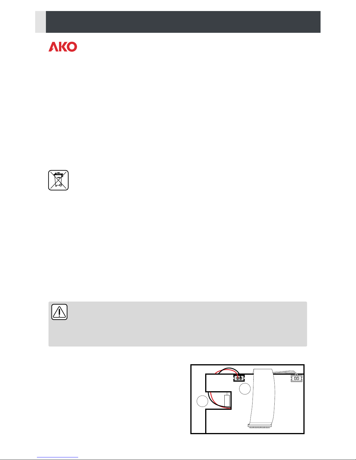
2.- Battery ......................................................................................................................................3
3.- Recommendations .....................................................................................................................4
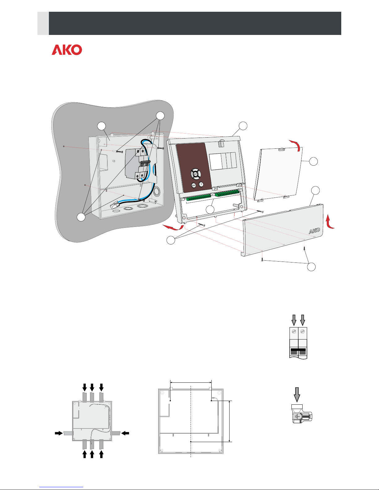
4.- Installation ................................................................................................................................5
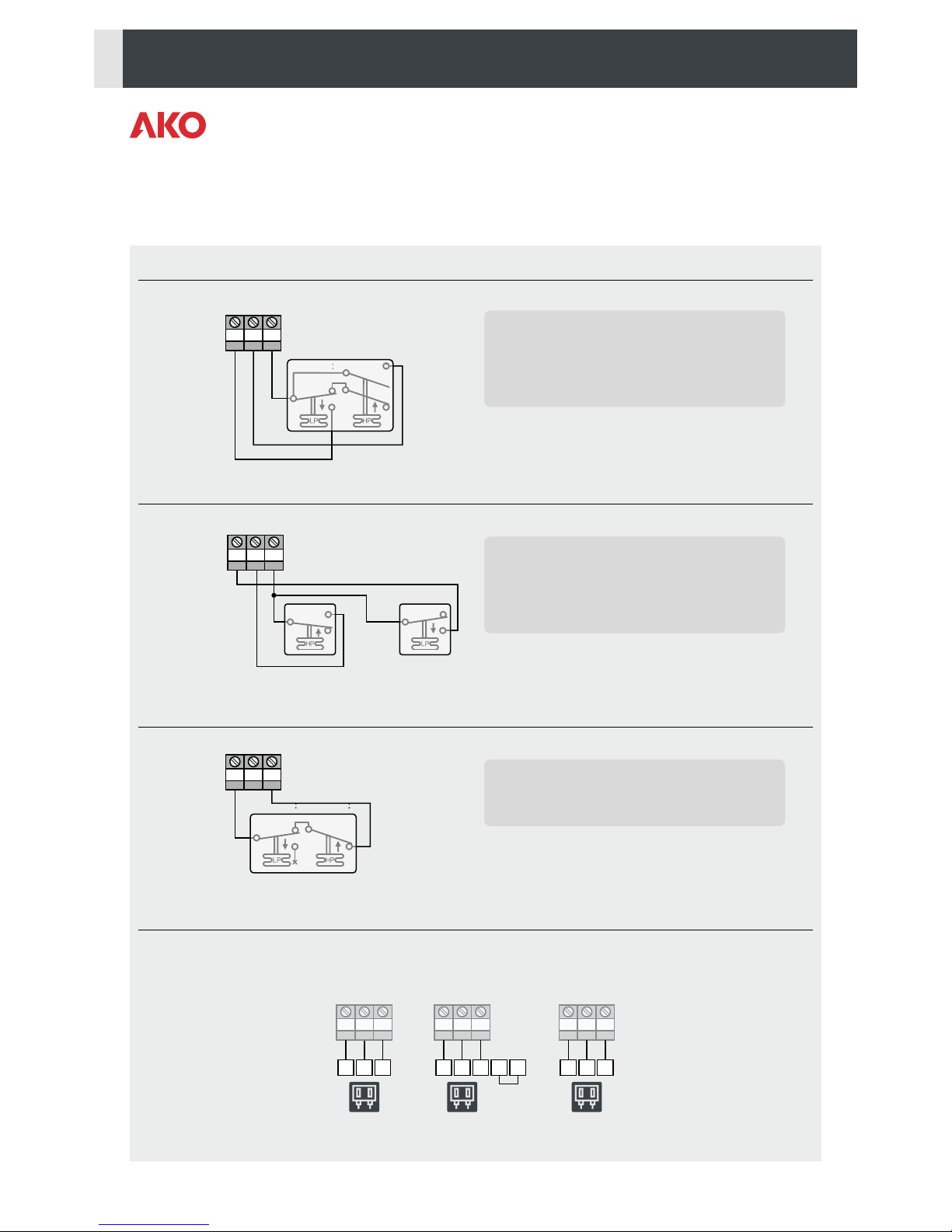
5.- Wiring .......................................................................................................................................6
5.1.- Pressure switch wiring options.........................................................................................7
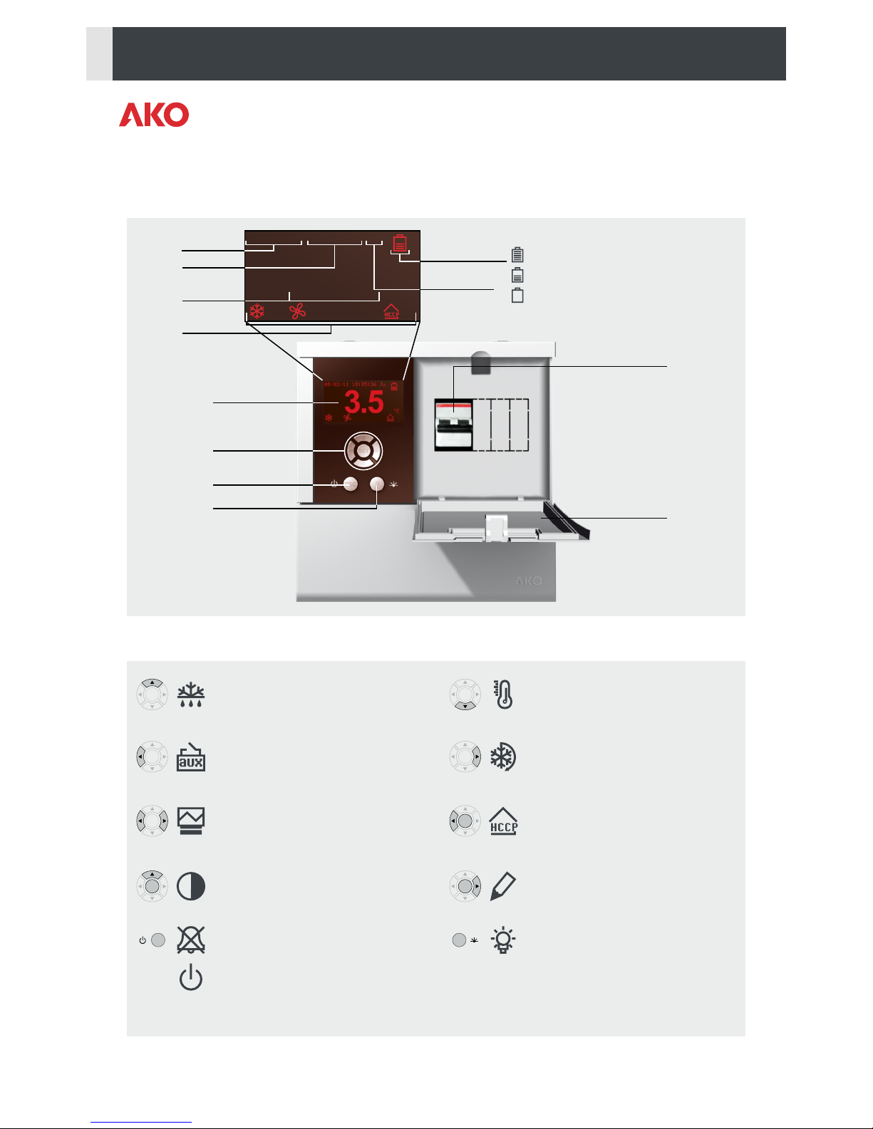
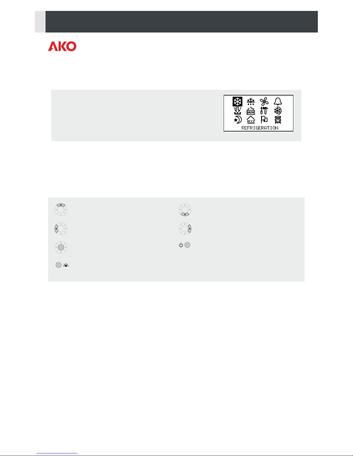
6.- Description ................................................................................................................................8
6.1.- Quick access to functions ................................................................................................8
6.2.- Status LEDs.....................................................................................................................9
6.3.- Messages........................................................................................................................9
7.- Programming menu .................................................................................................................10
7.1.- Basic initial configuration ..............................................................................................10
8.- Operation................................................................................................................................13
8.1.- Compressor control .......................................................................................................13
8.2.- Defrost control ..............................................................................................................15
8.3.- Fan control....................................................................................................................17
8.4.- Light control..................................................................................................................17
8.5.- Pump down function .....................................................................................................18
8.6.- Alarms ..........................................................................................................................19
8.7.- Data logging .................................................................................................................20
8.8.- HACCP logging .............................................................................................................21
9 Advanced configurations ............................................................................................................22
9.1.- Digital inputs.................................................................................................................22
9.2.- Auxiliary relay ...............................................................................................................23
9.3.- Access code (password).................................................................................................24
9.4.- Parameter transfer.........................................................................................................24
9.5.- Return to initial parameters ...........................................................................................24
9.6.- Program version ............................................................................................................24
10.- Connectivity ..........................................................................................................................25
11.- Parameters ............................................................................................................................26
12.- Technical specifications ..........................................................................................................31

1.- Presentation
PROPlus is the global electronic solution to manage positive and negative cold room stores, in combination with:
ŸStandard condensing units
ŸStreamlined condensing units
ŸOr as a service panel in decentralised systems.
It has a general circuit breaker of up to 16A, high IP65 degree of protection for installation in damp environments, is
easy to install thanks to its new connection strip and intuitive menus with help texts that make programming easier
using its backlit LCD display.
1.1.- Maintenance
Clean the surface of the unit with a soft cloth, water and detergent. Do not use abrasive detergents, petrol, white
spirits or solvents.
Units that include rechargeable electrical accumulators:
This unit includes accumulators that should be replaced when the unit's battery life is under the duration
assigned in its specifications. At the end of the useful life of the unit, the accumulators should be taken to a
selective waste collection centre or returned to the manufacturer.
1.2.- Cautions
-Using the unit not observing the manufacturer's instructions may alter the appliance safety requirements. Only
probes supplied by AKO should be used for the unit to operate correctly.
2
-From -40 ºC to +20 ºC, if the NTC probe is extended to 1000 m with at least 0.5 mm cable, the maximum
deviation will be 0.25 ºC (cable for probe extension ref. AKO-15586).
-Only NTC probes supplied by AKO should be used for the appliance to operate correctly.
-The AKO-15640 should be installed in a place protected from vibrations, water and corrosive gases, where the
ambient temperature does not exceed the value indicated in the technical data.
-For the reading to be correct, the probe should be used in a place without heat influences apart from the
temperature you want to measure or control.
-Always disconnect the power supply to do the wiring. The power supply circuit should have a main switch and
residual current protection outside the panel (according to 2 2 R.E.B.T.). The power supply cable will be H05VV-F
2 2
2x2.5 mm or H05V-K 2x2.5 mm .
IMPORTANT:
ŸThe function of each probe depends on the "probe setting" parameter (See probe configuration on page 11).
ŸThe AUXILIARY relay is programmable, and its operations depends on the configuration (See page 23).
ŸThe function of the digital inputs depends on the configuration (See page 22).
ŸThe recommended currents and powers are the maximum working currents and powers.
2.- Battery
You should connect the battery cable (1) and plate connector
(2) before installing the unit.
2
1
3

3.- Recommendations
ATTENTION!!
Disconnect the voltage before carrying out any operations inside the electrical panel.
All wiring should be according to current standards and should be carried out by authorised staff.
Only carry out the wiring foreseen in the wiring diagrams.
ŸWorking ambient temperature: 0 ºC to 50 ºC
ŸRated isolation voltage Ui = 440 V~
ŸElectrical panels with IP65 degree of protection
ŸCEM 1 Environment
ŸTerminals for copper conductors
ŸResistance to short-circuits Icc=4.5 kA
Panel installation:
Do not knock or move the panel abruptly.
Carry out the wiring according to the installation manual.
The probes and their cables should NEVER be installed in a conduit together with power, control or feeder cables.
The earth terminals that the panels contain are installed to guarantee the continuity of earthing, however, earthing
is not carried out by the terminal and should be carried out outside the panel.
The neutral ratings are TT or TNS. The IT rating should not be used.
Circuit breakers (protective switches) are of the phase/s + neutral, curve C type, guaranteeing switching and
protection against overcurrent.
Close the panel when your are not working on it.
Main switch connection and residual current protection outside the electrical panel according to low voltage
electrotechnical regulations.
Checks before starting the panel up:
The power supply voltages and frequencies will be those indicated in the table and diagram corresponding to each
panel model.
Check that there are no loose parts or foreign bodies on connections or switchgear.
Check that there is no dust or damp inside the panel.
Check the correct fastening of the switchgear and components.
Check the correct tightening of the screws and power connections.
Check the correct connection of the power conductors.
Check the correct insulation of the outer lines and that they do not mechanically force the inner connections of the
panel.
Checks during the panel start-up:
Check that no electric arcs occur.
Check that the relays or contactors do not produce ratios.
Check that there is no overheating in cables, controllers and the rest of the switchgear.
Checks after the first 24 hours of operation:
Check that no overheating occurs.
Retighten screws and power connections.
Periodical preventive maintenance:
The panel should remain closed using its anchors.
Retighten the power connections once a year.
Check the wear of the switchgear once a year.
4

H
F
E
AB
C
D
G
M
(fig. 1)
-Remove the connections cover (D).
-Separate the front (B) from the box (A).
-Choose the most suitable cable entry for the facility (fig. 3).
-Make the holes for the glands using the pre-drilled centres as a guide.
-Drill 3 holes on the wall following the box fixing holes (E) (fig. 4).
-Insert and tighten the 3 screws + plug (F).
-Insert the cables through the glands. Use the passing area shown in figure 3 for cable
guiding.
-Connect the battery (See page 3)
-Connect the power supply inlet to the circuit breaker as indicated in figure 2.
-Assemble the front on the box (B) carefully making sure that the cables are not
pinched.
-Insert and tighten the two screws on the front (G).
-Connect the cables following the diagrams in section 5.
-Close the connections cover (D), insert and tighten the fixing screws (H).
4.- Installation
(fig. 2)
POWER SUPPLY INPUT
230Vac +10% -15%
50/60Hz ±3Hz
L N
CONNECT ALL EARTH
CONNECTIONS IN
THIS TERMINAL
(fig. 3)
140
140
(fig. 4)
5

5.- Wiring
21 24 27 30 33 36 40
22 25 28 31 34 37 41
23 26 29 32 35 38 4239 43
MODBUS
RS-485 ALARM
RELAY
S3
S2
S1
DI1
DI2
GND
Tr
Tr
NC
NO
C
8A
LN PE
FAN
230Vac
2.2 A
LN
LN
NL
NL
N
L
CRANKASE
HEATER
230Vac
70W
LIGHT
230Vac
460W
CONDENSING
UNIT
230Vac
11.5A
2 CV
DEFROST
RESISTANCE
230Vac
11A
2500W
1 The auxiliary relay output function (terminals 40 and 41) is configurable (See page. 23).
AUXILIARY
RELAY1
ATTENTION: Make sure to turn of the equipment's power supply before handling it, as different areas
may be energised.
IMPORTANT
ŸThe recommended currents and powers are the maximum working currents and powers.
ŸThe function of each probe depends on the "probe configuration" parameter (See page 11).
ŸRemember that the control probe and registration probe should be configured separately if you
want to comply with EN12830.
6
POWER SUPPLY INPUT
230Vac +10% -15%
50/60Hz ±3Hz
CONNECT ALL EARTH
CONNECTIONS IN
THIS TERMINAL
AUX.

5.1.- Pressure switch wiring options
26
26
26
25
25
25
27
27
27
Combined High/Low pressure controller
Separate Low and High pressure controller
3 terminal High - Low pressure-controller
LOW HIGH
Pressure controller equivalence
LP HP
LP HP
5.1.- Pressure switch wiring options
LP
HP
5.1.- Pressure switch wiring options
Input 1 configuration: Low pressure input
Input 1 polarity: Normally open
Input 2 configuration: Severe external alarm
Input 2 polarity: Normally open
Aux. relay configuration: Pump down control
Configuración
Configuración
Configuración
26 2625 2527 27 27
12 22 2
14 4
A21 11 1
HIGH / LOW
ALCO RANCO
2625
B
C
DANFOS
/ PENN
Input 1 configuration: Low pressure input
Input 1 polarity: Normally open
Input 2 configuration: Severe external alarm
Input 2 polarity: Normally open
Aux. relay configuration: Pump down control
Input 1 configuration: Low pressure input
Input 1 polarity: Normally closed
Aux. relay configuration: Pump down control
5.1.- Pressure switch wiring options
7

03/02/11 13:35:26 Ju
ºC
3.5
6.- Description
Circuit breaker
Safety cover
Date Battery status
Time
Status
indicators
Temperature
Day of
the week
8
6.1.- Quick access to functions
Pressing it for 5 seconds allows changing
the SET POINT temperature.
Pressing it for 5 seconds activates or
deactivates the CONTINUOUS CYCLE.
Pressing it for 5 seconds accesses the
HACCP events log (See page 21).
Pressing it for 5 seconds allows editing the
description of the unit (See page 12).
It activates or deactivates the cold room
light (terminals 38 and 39). This function
stays active although the unit is in the m
mode.
Pressing it for 5 seconds activates or
deactivates the defrost.
Pressing it for 5 seconds activates or
deactivates the AUX relay. (According to config.
see page 23).
Pressing it for 5 seconds accesses the log list
(See page 20).
Pressing it for 5 seconds accesses the display
contrast setting, press N and Q to change it.
Silences the alarms (they are indicated on the
display).
Pressing it for 5 seconds activates or
deactivates the Stand-By mode. The display
shows the m symbol in this mode.
SET
SET
SET
SET
SET
SET
SET
SET
ESC
¿
Faulty or not connected (flashing)
Loading
Loading finished
Display
Browser
Help key
Escape key

9
6.2.- Status LEDs
6.3.- Messages
Permanent: Compressor relay active.
Flashing: It must be activated, but it is not
due to a parameter.
Defrost relay activated.
Continuous cycle mode active.
Permanent: Fan relay activated.
Flashing: It must be activated, but it is not
due to a parameter.
Defrost ended by time (See page 15).
Energy saving mode active (See page 13).
Alarm active.
Light relay activated.
Auxiliary relay activated by key.
Auxiliary relay indicating the unit's
status (ON/OFF).
Auxiliary active relay in pump
down mode.
Auxiliary relay activated per digital input.
Auxiliary relay active in second defrost
mode.
Flashing: Alarm silenced + alarm relay
deactivated.
Permanent: HACCP function active.
Flashing: HACCP alarm stored not displayed
(See page 21).
ACCESS CODE:
Access code (password) request to enter to the programming menu or to change the set point.
DEFROST:
Indicates that a defrost is being performed.
THERMOSTAT CONTROL:
The thermostat control function is active (See page 13).
EXTERNAL ALARM / SEVERE EXT. ALARM:
External alarm / severe external alarm activated by one of the digital inputs.
HIGH TEMP. ALARM / LOW TEMP. ALARM:
The temperature of probe 1 exceeds / is lower than the parameter programmed in Maximum alarm probe 1 /
Minimum alarm probe 1.
L. PRESSURE ALARM:
The low pressure controller has triggered due an excessively low pressure in the low pressure circuit, adjustment
stops.
ERROR PROBE 1, 2, or 3:
Probe 1, 2 or 3 broken (circuit open, crossed or temperature> 110 ºC or temp.<–55 ºC).
Auxiliary relay active copying relay
status for compressor.

10
It allows configuring the operating parameters.
7.- Programming menu
The programming menu allows adjusting the unit's parameters to the installation's needs.
Press the SET key for 5 seconds to access the programming menu. If the access code is activated, a 2 digit code is
requested (See page 24), if the code entered is not correct the unit will not enter programming.
The parameters are grouped by functions in 12 separate menus, to access a given menu, select it using the browser and
press SET (For more details, consult page 26).
Function of the keys in programming
7.1.- Basic initial configuration
3
Language
It defines the language of the menus and helps displayed on the screen.
G
Set point (SP)
It defines the temperature that should be inside the cold storage room (See page 13):
ŸMinimum: –40.0 *
ŸMaximum: 320 *
*(Depends on the bottom/top locking of the set point).
Calibration of Probe 1
It allows correcting the temperature detected by probe 1, this is particularly useful when the probe cannot be
located in the ideal place.
Moves the selection down or decreases the value of
the parameter.
Moves the selection to the right.
Displays the help for the selected parameter or
function.
Moves the selection up, or increases the value of the
parameter.
Moves the selection to the left.
Accepts the value or accesses the selected menu. Allows exiting a parameter without saving the
changes, returning to the previous menu or exiting
programming.
SET
SET
SET
SET
SET
ESC
¿
7.- Programming menu
The programming menu allows adjusting the unit's parameters to the installation's needs.
Press the SET key for 5 seconds to access the programming menu. If the access code is activated, a 2 digit code is
requested (See page 24), if the code entered is not correct the unit will not enter programming.
The parameters are grouped by functions in 12 separate menus, to access a given menu, select it using the browser and
press SET (For more details, consult page 26).
Function of the keys in programming
7.1.- Basic initial configuration
3
Language
It defines the language of the menus and helps displayed on the screen.
G
Set point (SP)
It defines the temperature that should be inside the cold storage room (See page 13):
ŸMinimum: –40.0 *
ŸMaximum: 320 *
*(Depends on the bottom/top locking of the set point).
Calibration of Probe 1
It allows correcting the temperature detected by probe 1, this is particularly useful when the probe cannot be
located in the ideal place.

21 24
22 23
TEM at S1/REG at S3 (According to EN 12830)
21 24
22 23
11
q
Connected sensors
Choose the correct option according to the no. of probes connected:
ŸSensor 1: If it has just one control probe. Defrost will end by time.
ŸSensor 1 and 2: If it has two probes, a control probe and another one for defrost (evaporator).
ŸSensor 1 and 3: If it has two probes, one for control and another for data logging or product temperature
(according to Probe setting), defrost will finish by time.
ŸSensor 1, 2 and 3: If it has three probes, one for control, and another for defrost and another for data
logging or product temperature (according to Probe setting).
Sensors to be displayed
It defines which probe will be displayed on the screen (probe 1, probe 2 or probe 3).
Display mode
It defines the information displayed on the screen during normal operation:
ŸProbe and clock: It displays the probe defined in the Sensors to be displayed parameter, the date, time
and day of the week.
ŸProbe and text: It displays the probe defined in the Sensors to be displayed parameter and the
description of the unit (See page 12).
ŸProbes, clock and text: It displays all the active probes, date, time and day of the week and the description
of the unit (See page 12). The configuration of the Sensors to be displayed does not intervene in this
mode.
Display unit
It defines the temperature display units (º Centigrade or º Fahrenheit).
Probe setting
It defines the function of the inputs of probe S1 and S3, the function of the S2 input is not configurable.
ŸTEM at S1/REG at S3: The temperature control, alarms and HACCP probe (Probe 1) is connected to the
S1 input and the temperature data logger probe (Probe 3) to the S3 input:
If probe 3 is configured as 2 defrost, the data logging deactivates.
ŸTEM and REG at S3: The temperature control, alarms and HACCP probe is also the data logger probe
(Probe 1) and it is connected in input S3, the product temperature probe is connected in the S1 input.
Probe 1 (Control of temperature, alarms, HACCP and data logger)
Probe 2 (Defrost / 2nd defrost)
Probe 3 (Product temperature probe / 2nd defrost)
Probe 1 (Control of temperature, alarms and HACCP)
Probe 2 (Defrost / 2nd defrost)
Probe 3 (Data logger / 2nd defrost)
TEM and REG at S3

12
Delay at Start-up
They allow delaying the start up of the installation when it receives electricity. This parameter prevents continuous
stoppages and start-ups of the installation in exceptional situations, for example, after a power cut, in test periods
or during the commissioning of the installation.
This is established in minutes.
Decimal point
It defines is the degree's decimal points are displayed or not, and therefore the resolution of the unit.
u
Date
If configures the current date (year, month, day).
Hour
If configures the current time (day of the week, day, minute).
A
Equipment description
The unit's display can be customised including the description of the installation
with a maximum length of 25 characters.
The description will not be displayed if the Display mode parameter is
configured as “Probe 1 and clock”.
To edit the description, press the SET and O keys for 5 seconds.
Text editor operation
To change the description, press the SET + O keys at the same time.
The changes made during edition are displayed on the bottom of the screen.
ŸUse the P, O, N and Q keys to move around the different characters and
options available and the SET key to validate the selection.
ŸSelect 9 to delete the character in grey.
ŸSelect L or K to move around the text being edited.
ŸSelect 8 to save the changes and exit the edition menu.
:
Contrast
To change the contrast of the screen, press the SET and O keys for 5 seconds.
Adjust the screen's contrast pressing the N and Q keys.
Press SET to validate.

13
8.- Operation
8.1.- Compressor control
NORMAL OPERATION
CONTROL BY THERMOSTAT
Temperature is controlled by an external thermostat instead of probe 1, and to do so one of the digital inputs must be
configured as "Thermostat control".
This configuration cancels the probe inputs, and therefore temperatures will not be displayed nor will the functions
associated with them be carried out (temperature, alarms, HACCP logging, etc.).
CONTINUOUS CYCLE MODE
Use this function to cool the cold rooms before loading products.
It is activate pressing the O key for 5 seconds, the display shows the % icon while this mode is active.
ENERGY SAVING MODE
It allows energy saving in the periods of low activity of the cold room, and in this way reduces the installation's
electricity consumption. The display will show the Z icon when this mode is active.
It is activated using time programming, using the Energy saving start parameter on the u menu with the options:
ŸDay: Defines the days this mode will be activated on;
žDeact.: It will never be activated.
žMonday/Tuesday/Wednesday/Thurdsay/Friday/Saturday/Sunday: It will only activate on the chosen day.
žMon-Sun: It will activate everyday (from Monday to Sunday).
žMon-Sat: It will activate everyday except Sunday.
žMon-Fri: It will activate everyday except Saturday and Sunday.
žSat-Sun: It will only activate on Saturday and Sunday.
ŸHour: It times the energy saving mode start hour.
ŸMinute: It times the energy saving mode start minute.
ON
SP SP+Dif.
OFF
COMP.
ºC
When the temperature in probe 1 reaches the set
point value (SP) plus the probe's differential, the
compressor activates and makes the temperature
drop. When the set point value (SP) is reached, the
compressor stops.
When this mode is activated, the compressor starts
to operate continuously and without taking the set
point into account, until the time configured in the
Continuous cycle duration parameter passes, or
until the O key is pressed again for 5 seconds.
The unit will immediately return to normal operation.
ON
SP
Continuous
Cycle Duration
SP+C1
OFF
COMP.
ºC
8.- Operation
8.1.- Compressor control
NORMAL OPERATION
CONTROL BY THERMOSTAT
Temperature is controlled by an external thermostat instead of probe 1, and to do so one of the digital inputs must be
configured as "Thermostat control".
This configuration cancels the probe inputs, and therefore temperatures will not be displayed nor will the functions
associated with them be carried out (temperature, alarms, HACCP logging, etc.).
CONTINUOUS CYCLE MODE
Use this function to cool the cold rooms before loading products.
It is activate pressing the O key for 5 seconds, the display shows the % icon while this mode is active.
ENERGY SAVING MODE
It allows energy saving in the periods of low activity of the cold room, and in this way reduces the installation's
electricity consumption. The display will show the Z icon when this mode is active.
It is activated using time programming, using the Energy saving start parameter on the u menu with the options:
ŸDay: Defines the days this mode will be activated on;
žDeact.: It will never be activated.
žMonday/Tuesday/Wednesday/Thurdsay/Friday/Saturday/Sunday: It will only activate on the chosen day.
žMon-Sun: It will activate everyday (from Monday to Sunday).
žMon-Sat: It will activate everyday except Sunday.
žMon-Fri: It will activate everyday except Saturday and Sunday.
žSat-Sun: It will only activate on Saturday and Sunday.
ŸHour: It times the energy saving mode start hour.
ŸMinute: It times the energy saving mode start minute.
When the temperature in probe 1 reaches the set
point value (SP) plus the probe's differential, the
compressor activates and makes the temperature
drop. When the set point value (SP) is reached, the
compressor stops.
8.- Operation
8.1.- Compressor control
NORMAL OPERATION
CONTROL BY THERMOSTAT
Temperature is controlled by an external thermostat instead of probe 1, and to do so one of the digital inputs must be
configured as "Thermostat control".
This configuration cancels the probe inputs, and therefore temperatures will not be displayed nor will the functions
associated with them be carried out (temperature, alarms, HACCP logging, etc.).
CONTINUOUS CYCLE MODE
Use this function to cool the cold rooms before loading products.
It is activate pressing the O key for 5 seconds, the display shows the % icon while this mode is active.
ENERGY SAVING MODE
It allows energy saving in the periods of low activity of the cold room, and in this way reduces the installation's
electricity consumption. The display will show the Z icon when this mode is active.
It is activated using time programming, using the Energy saving start parameter on the u menu with the options:
ŸDay: Defines the days this mode will be activated on;
žDeact.: It will never be activated.
žMonday/Tuesday/Wednesday/Thurdsay/Friday/Saturday/Sunday: It will only activate on the chosen day.
žMon-Sun: It will activate everyday (from Monday to Sunday).
žMon-Sat: It will activate everyday except Sunday.
žMon-Fri: It will activate everyday except Saturday and Sunday.
žSat-Sun: It will only activate on Saturday and Sunday.
ŸHour: It times the energy saving mode start hour.
ŸMinute: It times the energy saving mode start minute.
When this mode is activated, the compressor starts
to operate continuously and without taking the set
point into account, until the time configured in the
Continuous cycle duration parameter passes, or
until the O key is pressed again for 5 seconds.
The unit will immediately return to normal operation.
ON
SP2
(SP2)+Dif.
OFF
COOL
ºC
Operation is the same as in the normal ode, but
increasing the set point the amount of degrees
defined in the Set point energy saving
parameter.
(SP2= Set point during energy saving)
8.- Operation
8.1.- Compressor control
NORMAL OPERATION
CONTROL BY THERMOSTAT
Temperature is controlled by an external thermostat instead of probe 1, and to do so one of the digital inputs must be
configured as "Thermostat control".
This configuration cancels the probe inputs, and therefore temperatures will not be displayed nor will the functions
associated with them be carried out (temperature, alarms, HACCP logging, etc.).
CONTINUOUS CYCLE MODE
Use this function to cool the cold rooms before loading products.
It is activate pressing the O key for 5 seconds, the display shows the % icon while this mode is active.
ENERGY SAVING MODE
It allows energy saving in the periods of low activity of the cold room, and in this way reduces the installation's
electricity consumption. The display will show the Z icon when this mode is active.
It is activated using time programming, using the Energy saving start parameter on the u menu with the options:
ŸDay: Defines the days this mode will be activated on;
žDeact.: It will never be activated.
žMonday/Tuesday/Wednesday/Thurdsay/Friday/Saturday/Sunday: It will only activate on the chosen day.
žMon-Sun: It will activate everyday (from Monday to Sunday).
žMon-Sat: It will activate everyday except Sunday.
žMon-Fri: It will activate everyday except Saturday and Sunday.
žSat-Sun: It will only activate on Saturday and Sunday.
ŸHour: It times the energy saving mode start hour.
ŸMinute: It times the energy saving mode start minute.
Operation is the same as in the normal ode, but
increasing the set point the amount of degrees
defined in the Set point energy saving
parameter.

14
The Set point energy saving parameter defines what the set point will be when this mode is active and
the Energy saving duration parameter defines the duration of this mode in hours. It never activates if it is configured
at 0.
This mode may optionally be activated and deactivated whenever you want using the external button connected to one
of the digital inputs, and to do so the corresponding input should be configured as "Remote energy saving”.
COMPRESSOR PROTECTION DELAY
This protects the compressor, preventing continuous stops and start-ups in certain exceptional cases.
The Comrpessor Protection parameter allows choosing between 2 types of delay:
OFF-ON: Minimum time the compressor should stay stopped before each start-up.
ON: Minimum time the compressor should stay operating before each start-up.
The Protection delay time parameter defines the time of the previous parameter.
OPERATION IN THE EVENT OF A FAULT IN PROBE 1
If probe 1 fails (failure, disconnection, etc. ), the compressor operates according to times programmed in the following
parameters:
Compressor ON fault s1: Time of the compressor operating in the event of a fault in probe 1.
Compressor OFF fault s1: Time of the compressor stopped in the event of a fault in probe 1.
SET POINT LOCKINGS
Using the Set Point upper limit and Set Point lower limit parameters, it is possible to set a top and bottom limit for
the Set point (SP) parameter, which prevents being able to set a set point that is too low or too high that might
damage the installation or the stored product.
STOP COMPRESSOR WHEN THE DOOR IS OPENED
This defines if the compressor will be stopped whenever the cold room's door is opened. To do so, one of the digital
inputs should be configured as "door contact" (See page 22).
If the door stays open longer than the value programmed in the Inact. with door open parameter, the compressor will
return to normal operation (See page 22).
ON
Fault in Probe 1
COMP.
OFF COMP.
OFF
COMP.
ON COMP.
ON
OFF
COMP.
Time
ON
ON
ONOFF-ON SPSP SP+Dif. SP+Dif.
Delay time Delay time
OFF OFF
COMP. COMP.
Time
Time

15
8.2.- Defrost control
Type of defrost
This is chosen using the Defrost type parameter that defines the behaviour of the controller during the defrost
process.
DEFROST DEFROST
DRIP TIME
FAN START UP DELAY
"DEF” MESSAGE
CONTROL CONTROL
time
ºC
Max. B C
A
SP
SP+Dif.
D
DEFROST DEFROST
DRIP TIME
FAN START UP DELAY
"DEF" MESSAGE
CONTROL CONTROL
Description
Parameter
A
Time between two defrost starts
Defrost frequency
B
Maximum defrost duration
Defrost duration
C
Maximum duration of the defrost message
Message duration
D
Final defrost temperature by probe 2
Defrost final temperature
SP
Temperature set point
Set point (SP)
Dif.
Temperature set point differential
Sensor 1 differential
Types of
defrost
Description
Parameter configuration
Compressor
stopping
The compressor stops and defrost is carried out statically.
H Defrost type: Resistances
X Fans state during defrost: Disconnected
By air
The fans are activated and the compressor stops, defrost is
carried out forcing the movement of air through the
evaporator.
H Defrost type: Resistances
X Fans state during defrost: Connected
By resistances
The defrost resistances are activated and the compressor stops,
defrost is carried out by the heat supply from the resistances.
H Defrost type: Resistances
X Fans state during defrost: Disconnected
By Cycle
inversion
A 4-way valve is activated that inverts the cooling generator
circuit and the compressor starts up, forcing the defrost.
H Defrost type: Reverse cycle
X Fans state during defrost: Disconnected
By simple
hot gas
A valve is activated that sends the discharge from the
compressor to the evaporator inlet. Using check valve
prevents the hot gas from returning along the liquid line.
H Defrost type: Reverse cycle
X Fans state during defrost: Disconnected
8.2.- Defrost control
Type of defrost
This is chosen using the Defrost type parameter that defines the behaviour of the controller during the defrost
process.

16
Defrost start
Defrost will start if:
ŸThe time programmed in the Defrost frequency parameter has passed since the start of the last defrost.
The parameter Defrost mode defines how this time is counted:
žFrequency: Total time passed between defrost starts.
žCompressor sum: Total time of the compressor operating between defrost starts.
žReal Time Clock: Defrost starts when one of the times programmed in the Defrost 1 to 8 on
the u menu is reached. (The defrost frequency is not taken into account).
ŸWe press the N key for 5 seconds.
End of defrost
The defrost stops if:
ŸThe temperature programmed in the Defrost final temperature has been reached in probe 2 (this requires
having a defrost probe connected to S2).
ŸThe time configured in the Defrost duration has passed (maximum defrost duration). The I icon is shown on
the display if the Signals end defrost time parameter is configured in “Yes”.
ŸWe press the N key for 5 seconds.
REMARK: If the Defrost duration is configured to 0, no defrosts are carried out.
Drip time after defrost
This is establishing using the Drip time parameter of the H menu and defines the time added at the end of the defrost
to allow removing any water left in the evaporator.
During this time, the compressor and fans will be stopped (except if the defrost is by air).
Message displayed during defrost
This is established using the Defrost message parameter, and you can choose between displaying the real
temperature captured by probe 1, show the temperature capture by probe 1 at the start of the defrost, or display the
DEFROST message.
The Message duration parameter defines how long this message is displayed, after the drip time and start up delay of
the fans (See page 15).
Other parameters
Using the Defrost at Start-up parameter, you can configure if the unit carries out or not a defrost when it receives
power (first start up or after a fault in the power supply).
If the "YES" option is chosen, defrost starts after the time defined in the Defrost delay at Start-up parameter on the
H menu.
2nd defrost
It operates in the same way as the defrost, but acts on the auxiliary relay, controlled by probe 2 or 3 and is used to
control the defrost in a second evaporator. (The AUX relay must be configured as 2nd defrost).
The configuration parameters of the 2nd defrost are configured from the v menu.
Remote defrost
This function allows activating the defrost of the unit using an external button, connecting it to one of the digital inputs
that must be configured as "remote defrost”.

17
8.3.- Fan control
Fan control is carried out using probe 2 and taking the following parameters into account:
ŸFan stop temperature: It defines the temperature at which the fans stop.
ŸFans differential s2: It defines the temperature differential of probe 2 (evaporator).
ŸStop when compressor OFF?: It defines if the fans stop in each compressor stop.
ŸFans state during defrost: It defines the status of the fans during the defrost.
ŸFans delay after defrost: If configures the time that passes before starting the fans up, at the end of a defrost.
ŸStop when opening door: It defines if the fans are stopped when the cold room's door is opened (this requires
having configured one of the digital inputs as door contact).
If the door stays open longer than the value programmed in the Inact. with door open parameter, the fans
return to normal operation.
If probe 2 is not connected or an error in the probe is detected, the fans will always be operating without taking into
account the temperature related parameters, but taking the rest of the parameters into account.
8.4.- Light control
The unit has an additional relay to control the cold room's lights.
Just press the ? key to turn the lights on/off.
This function is even active when the unit is in Stand-by.
Light timing
The unit activates the lights whenever the cold room's door is detected to have been opened, and turns them off after
the time programmed in the Cold room light timing parameter, even though the door stays open. If time is
configured at “0”, timing does not start.
One of the digital inputs should be configured as "Door contact”.
ON
ON
Temp. fan stop
Differential fan S2
Only if “Stop if
compressor OFF?”=Yes
OFF
OFF
ºC
COMP.
VENT.
TEMP.
in
probe 2
Time
8.3.- Fan control
Fan control is carried out using probe 2 and taking the following parameters into account:
ŸFan stop temperature: It defines the temperature at which the fans stop.
ŸFans differential s2: It defines the temperature differential of probe 2 (evaporator).
ŸStop when compressor OFF?: It defines if the fans stop in each compressor stop.
ŸFans state during defrost: It defines the status of the fans during the defrost.
ŸFans delay after defrost: If configures the time that passes before starting the fans up, at the end of a defrost.
ŸStop when opening door: It defines if the fans are stopped when the cold room's door is opened (this requires
having configured one of the digital inputs as door contact).
If the door stays open longer than the value programmed in the Inact. with door open parameter, the fans
return to normal operation.
If probe 2 is not connected or an error in the probe is detected, the fans will always be operating without taking into
account the temperature related parameters, but taking the rest of the parameters into account.
8.4.- Light control
The unit has an additional relay to control the cold room's lights.
Just press the ? key to turn the lights on/off.
This function is even active when the unit is in Stand-by.
Light timing
The unit activates the lights whenever the cold room's door is detected to have been opened, and turns them off after
the time programmed in the Cold room light timing parameter, even though the door stays open. If time is
configured at “0”, timing does not start.
One of the digital inputs should be configured as "Door contact”.

ON
SP + DIF
Liquid
solenoid
Temperature
Low pressure
controller
Fault in pressure
controller Fault in pressure
controller
Low Pressure
Alarm
Compressor
Pressure in
evaporator
ON
ON
+
Pump
down
duration
Pump down
ON delay
OFF
SP
OFF
OFF
AUX
Entrada
digital
COMP.
Time
SP SPSP+DIF. SP+DIF.
18
8.5.- Pump down function
This function foresees problems in the compressor caused by movements of coolant, using a stop/start technique of the
installation, controlled via the liquid solenoid, the low pressure controller and the compressor itself.
The auxiliary relay must be configured as "Pump down control", the liquid solenoid must be connected to the 40 and 41
terminals and there must be a low pressure controller connected as indicated in the diagrams (See page 7).
STOP
When the temperature in probe 1 reaches the set point (SP) value, the liquid solenoid closes.
Due to the compressor continuing to operate (COMP. relay ON), the pressure drops quickly in the evaporator, and
therefore activates the low pressure controller and the compressor stops.
If during this process the low pressure controller does not detect the change of pressure, the controller will stop after the
safety time defined in Pump down duration.
START
When the temperature in probe 1 reaches the set point value plus the differential, the liquid solenoid opens, making the
pressure in the evaporator increase and deactivating the low pressure controller, which will start the compressor up.
When a balance is reached between the high and low pressure before the start up, this is much gentler and lengthens
the life of the compressor.
If after a time after opening the liquid solenoid the low pressure controller does not deactivate, the controller closes the
solenoid again and activates the low pressure alarm. This time is defined using the Pump down On delay parameter.
STAND-BY WITH PUMP DOWN
If the pump down function is active and the compressor is operating, when the Stand-by function starts the unit stops
the compressor in a controlled manner as explained in the "STOP" section and displays on the screen the "Pump
down" message, and when it has finished, it automatically goes to the Stand-by mode.

19
8.6.- Alarms
The unit warns the user with a message on the screen of the activation of a relay or the
activation of an acoustic signal in certain circumstances, according to the programming of
the following parameters:
Alarm configuration
It defines how the values of the different temperature alarms are defined:
Relative to the SP: They are defined indicating the temperature variation regarding the set point for the alarm to
activate. This option enables us to change the set point without having to reset the maximum
and minimum alarms.
Absolute: They are defined indicating the absolute temperature value for the alarm to activate.
Maximum / minimum temperature alarm
It displays the message “HIGH TEMP ALARM” or “LOW TEMP. ALARM” when the temperature in probe 1 reaches the
value configured in the Maximum alarm sensor 1 and Minimum alarm sensor 1 parameters respectively.
The sound alarm and alarm relay is activated.
Alarm differential
It establishes the differential for the maximum and minimum alarm parameters (hysteresis).
Example
We configure the following parameters in a controller:
Set point=2, Maximum alarm probe 1=10, Alarm differential=2
ŸIf it is configured as “Relative to the SP”, the maximum temperature alarm activates when 12 degrees
are reached in probe 1, and deactivates when 10 degrees are reached.
ŸIf it is configured as “Absolute”, the maximum temperature alarm activates when 10 degrees are
reached in probe 1, and deactivates when 8 degrees are reached.
Delays
They define the delay time in minutes from a certain event, until the activation of the temperature alarms.
ŸTemperature alarm delay: Delay from when the temperature is reached.
ŸStart-up delay: Delay from which the unit receives power supply (start up or after a fault in the power supply). This
allows starting up the installation avoiding constant alarm statuses.
ŸAlarm delay after defrost: Delay at the end of a defrost.
ŸOn-Off door alarm delay: Delay from the deactivation of the digital input configured as door contact.
ŸOff-On door alarm delay: Delay from the activation of the digital input configured as door contact.
Alarm relay after key
This defines the status of the alarm relay after silencing it (pressing the ESC key).
External alarm / severe external alarm
It displays the EXTERNAL ALARM or SEVERE EXT. ALARM, on activating the digital input configured as external
alarm or severe external alarm. The severe external alarm also stops the unit's control functions (compressor, fans,
defrost and auxiliary relay).
One of the digital inputs must be configured as external alarm or as severe external alarm.
The sound alarm and alarm relay is activated.

20
Defrost finished by time alarm
The icon I is displayed when a defrost ends for maximum time. (The Signal end defrost time must be configured as
“Yes”).
The sound alarm and alarm relay is not activated.
Low pressure alarm
It displays the LOW PRESSURE ALARM message when low pressure is detected in the circuit, or if pressure does not
increase during the starting operation from pump down (See page 18). In both cases, there should be a low pressure
controller connected to the unit (See page 7).
The compressor stops and activates the sound alarm and alarm relay is not activated.
8.7.- Data logging
It allows displaying the temperatures logged during the selected time period.
The probe designed for temperature logging depends on the probe configuration (See page 11).
Press the P and O keys at the same time for 5 seconds to access data logging.
Data is saved in log blocks and the unit can store up to 366 blocks and each block contains 96 logs.
Each log contains the temperature measured by the unit, and the data and time of this measurement.
The "registry interval” parameter defines the time that passes between the capture of a datum and the next one.
When the last available block (N365) has been completed, the unit starts again with the first block (N000), therefore,
the time interval the unit is capable of storing depends on the configured log interval.
Use the N or Q keys to select a block and press SET to display the logged data.
Display of the logged data.
Defrost finished by time alarm
The icon I is displayed when a defrost ends for maximum time. (The Signal end defrost time must be configured as
“Yes”).
The sound alarm and alarm relay is not activated.
Low pressure alarm
It displays the LOW PRESSURE ALARM message when low pressure is detected in the circuit, or if pressure does not
increase during the starting operation from pump down (See page 18). In both cases, there should be a low pressure
controller connected to the unit (See page 7).
The compressor stops and activates the sound alarm and alarm relay is not activated.
8.7.- Data logging
It allows displaying the temperatures logged during the selected time period.
The probe designed for temperature logging depends on the probe configuration (See page 11).
Press the P and O keys at the same time for 5 seconds to access data logging.
Data is saved in log blocks and the unit can store up to 366 blocks and each block contains 96 logs.
Each log contains the temperature measured by the unit, and the data and time of this measurement.
The "registry interval” parameter defines the time that passes between the capture of a datum and the next one.
When the last available block (N365) has been completed, the unit starts again with the first block (N000), therefore,
the time interval the unit is capable of storing depends on the configured log interval.
Use the N or Q keys to select a block and press SET to display the logged data.
Log date
Block in
use
Log time Log
interval
Block no.
SET Scrolling through logs
Data display
Graph display
SET
Table of contents
Other AKO Control Panel manuals

AKO
AKO PROPlus 3PH Series User manual

AKO
AKO PROPlus AKO-1565 Series User manual

AKO
AKO AKO-17630 User manual

AKO
AKO PROCool AKO-17632 User manual

AKO
AKO PROPlus 3PH Series User manual

AKO
AKO PROPlus User manual

AKO
AKO AKO-15690 User manual

AKO
AKO PROPlus 3PH Series User manual

AKO
AKO PROCool AKO-17635-1 User manual

AKO
AKO PROCool AKO-17635-2 User manual
Popular Control Panel manuals by other brands

Pego
Pego VISION Series Use and maintenance manual

Pyronix
Pyronix ATLAS8PLUS Installation & maintenance

nvent
nvent Raychem ECW-GF-DP Installation and operation instructions

GCC Technologies
GCC Technologies LaserPro C180II quick start guide

Frick
Frick QUANTUM LX Control Panel Operation

FlameStop
FlameStop PFS200-2 Installation and operation manual