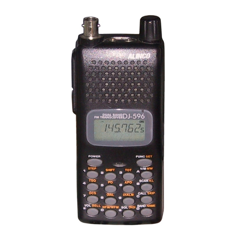
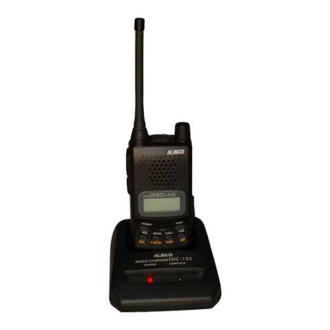
Alinco DJ-493 User manual

DJ-493
DJ-496/438
Service Manual
CONTENTS
SPECIFICATIONS
1) G EN ERAL.............................................................................2
2) TRANSM ITTER...................................................................2
3) RECEIVER............................................................................2
CIRCUIT DESCRIPTION
1) Receiver S ystem ............................................................3, 4
2) Tr nsmitter System .............................................................4
3) PLL Synthesizer C ircuit
...............................................
4, 5
4) CPU nd Peripher l Circuits
............................
.
.........
5, 6
5) M38267M8L252GP (XA0725)..................................... 6 - 8
SEMICONDUCTOR DATA
1) NMJ2070M T 1 (XA0210) ..................................................9
2) AT24C16N-10SI-2.7TER (XA0368)................................9
3) M5222FP-600C (XA0385)
.............................................
10
4) TK14521MTL (XA0515).................................................. 11
5) M64076AGP (XA0352)
................................................... 12
6) NJM2904V-TE1 (XA0573) ............................................. 12
7) NJM2902V-TE1 (XA0596) ............................................. 12
8) S-81350HG-KD-T1 (XA0724) ....................................... 13
9) S-80845ALMP-EA9-T2 (XA0620) ................................ 13
10) 2SK2975 (XE0038)........................................................... 13
11) Tr nsistor, Diode, nd LED Ontline Dr wings
...........
14
12) LCD Connection (EL0044)............................................ 14
SNCO, inc.
EXPLODED IEW
1) Front View............................................................................15
2) R e rView............................................................................16
PARTS LIST (DJ-493)
MAIN U nit
.................................................................... 17-21
Mech nic l P rts..............................................................22
P cking P rts......................................................................22
PARTS LIST (DJ-496)
MAIN U nit.....................................................................23-27
Mech nic l P rts...............................................................28
P cking P rts......................................................................28
ADJUSTMENT
1) Required Test Equipment
........................................
29, 30
2) Adjustment M ode
.......................................................31-34
PC BOARD IEW
MAIN U nit.....................................................................35, 36
SCHEMATIC DIAGRAM
.............................................
37, 38
BLOCK DIAGRAM
........................................................
39, 40
All manuals and user guides at all-guides.com
all-guides.com

SPECIFICATIONS
1) GENERAL
Frequency cover ge
Mode
Ch nnel steps
Memory ch nnels
Antenn connector
Frequency st bility
Microphone input imped nce
Power supply requirement
Current dr in ( t 13.8 V DC)
Us ble temper ture r nge
Dimensions
(Projections not included)
Weight
DTMF (DJ-496)
Sub udible Tone(CTCSS)
Sub udible Tone (DCS)
2) TRANSMITTER
Output power
Modul tion system
Spurious emissions
M x. frequency devi tion
3) RECEI ER
Receive system
Intermedi te frequencies
Sensitivity(12dB SINAD)
Selectivity
Audio output power
TX 430 ~ 449.995MHz RX 430 ~ 449.995MHz
TX 430 - 439.995MHz RX 430 ~ 439.995MHz
TX 450 ~ 469.995MHz RX 450 ~ 469.995MHz
TX 430 ~ 449.995MHz RX 430 ~ 449.995MHz
TX 430 ~ 439.995MHz RX 430 ~ 439.995MHz
TX 450 ~ 469.995MHz RX 450 ~ 469.995MHz
DJ-493T
E
TA2
DJ-496T
E
DJ-438TA2
F3E (FM)
5,10,12.5,15,20,25, & 30kHz
40ch nnels+1 CALL ch nnel
BNC (50Q unb l nced)
±5 ppm
2kfi nomin l
7.0 - 16.0V DC (neg tive ground)
1.4A (typic l) Tr nsmit high t 5W
200mA (typic l) Receive t 280mW
50mA (typic l) st ndby
20mA (typic l) B ttery s ve on
-10 ~ +60°C (14 ~ 140°F)
56 (W) x 124 (H) x 40 (D) mm (with EBP-48N)
2.2"(W) x 4.88"(H) x 1,57"(D) inches (with EBP-48N)
Approx. 375g (13.2oz) (with EBP-48N)
16 Buttons Keyp d
encoder/decoder inst lled (39tones)
encoder/decoder inst lled (104codes)
Approx. 4W EBP-48N inst lled
Approx. 5W 13.8V DC
Approx. 0.8W (LOW)
V ri ble re ct nce frequency modul tion
Less th n -60dB
±5 kHz
Double conversion superheterodyne
1st 45.1 MHz/2nd 455kHz
Less th n -12.0dB|x (0.25V)
-6dB :12kHz or more
-60dB : 26kHz or less
280mW (typic l with n 8Q lo d)
200mW (8i3 10% THD)
2
All manuals and user guides at all-guides.com

CIRCUIT DESCRIPTION
1) Receiver System
The receiver system is double superheterodyne system with 45.1 MHz first IF nd 455kHz second IF.
1. Front End
The received sign l t ny frequency in the 430.00- to 449.995-MHz r nge is
p ssed through the low-p ss filter (L2, L3, L8, C2, C9, C10, C11, nd C62)
nd high-p ss filter (C56, C57, C61, L25 nd D25), nd mplified by the RF
mplifier (Q9). The sign l from Q9 is then p ssed through the tuning circuit
(L19, L20, L21 nd v ric ps D12, D13 nd D14) nd converted into 45.1MHz
by the mixer (Q10). The tuning circuit, which consists of L25, L19, L20, L21,
D15, D12, D13 nd D14 is controlled by the tr cking volt ge form the CPU so
th t it is optimized for the reception frequency. The loc l sign l from the VCO
is p ssed through the buffer (Q11), nd supplied to the source of the mixer
(Q10). The r dio uses the lower side of the superheterodyne system.
2. IF Circuit The mixer mixes the received sign l with the loc l sign l to obt in the sum of
nd difference between them. The cryst l filter (XF1) selects 45.1MHz fre
quency from the results nd elimin tes the sign ls of the unw nted frequen
cies. The first IF mplifier (Q8) then mplifies the sign l of the selected fre
quency.
3. Demodulator Circuit
After the sign l is mplified by the first IF mplifier (Q8), it is input to pin 16 of
the demodul tor IC (IC4). The second loc l sign l of 45.555MHz, which is
oscill ted by the intern l oscill tion circuit in IC4 nd cryst l (X2). Then, these
two sign ls re mixed by the intern l mixer in IC4 nd the result is converted
into the second IF sign l with frequency of 455kHz. The second IF sign l is
output from pin 3 of IC4 to the cer mic filter (FL1), where the unw nted fre
quency b nd of th t sign l is elimin ted, nd the resulting sign l is sent b ck
to the IC4 through pin 5.
The second IF sign l input vi pin 5 is demodul ted by the intern l limiter
mplifier nd qu dr ture detection circuit in IC4, nd output s n udio sign l
through pin 10.
4. Audio Circuit
The udio sign l from pin 10 of IC4 is compens ted to the udio frequency
ch r cteristics in the de-emph sis circuit (R106, R107, C128, C127) nd m
plified by the AF mplifier (Q27). The sign l is then input to pin 2 of the elec
tronic volume (IC6) for volume djustment, nd output from pin 1. The d
justed sign l is sent to the udio power mplifier (IC5) through pin 2 to drive
the spe ker.
3
All manuals and user guides at all-guides.com

5. Squelch Circuit The sign l except for the noise component in AF sign l of 104 is cut by the
ctive filter inside 1C. The noise component is mplified nd rectified, then
converted to the DC volt ge to output from pin13 of IC4. The volt ge is led to
pin 2 of CPU nd comp red with the setting volt ge. The squelch will open if
the input volt ge is lower th n the setting volt ge.
2) Transmitter System
1. Modulator Circuit The udio sign l is converted to n electric sign l in either the intern l or
extern l microphone, nd input to the microphone mplifier (IC8). IC8 con
sists of two oper tion l mplifiers; one mplifier (pins 5, 6, nd 7) is composed
of pre-emph sis nd IDC circuits nd the other (pins 1, 2, nd 3) is composed
of spl tter filter. The m ximum frequency devi tion is obt ined by VR1 nd
input to the c thode of the v ric p of the VCO, to ch nge the electric c p city
in the oscill tion circuit. This produces the frequency modul tion.
2. Power Amplifier Circuit
The tr nsmitted sign l is oscill ted by the VCO, mplified by the pre-drive IC
(IC1) nd drive mplifier (04), nd input to the fin l mplifier (02). The sign l
is then mplified by the fin l mplifier (02) nd led to the ntenn switch (D2)
nd low-p ss filter (L5, L3,12, C24, C11, 010, nd C9), where unw nted high
h rmonic w ves re reduced s needed, nd the resulting sign l is supplied
to the ntenn .
3. APC Circuit P rt of the tr nsmission power from the low-p ss filter is detected by D7, con
verted to DC, nd then mplified by differenti l mplifier. The output volt ge
controls the bi s voit ge from the source of 02 nd 04 to m int in the tr ns
mission power const nt.
3) PLL Synthesizer Circuit
1. PLL The dividing r tio is obt ined by sending d t from the CPU (IC9) to pin 2 nd
sending clock pulses to pin 3 of the PLL IC (IC2). The oscill ted sign l from the
VCO is mplified by the buffer (05, 037) nd input to pin 6 of IC2. E ch
progr mm ble divider in IC2 divides the frequency of the input sign l by N
ccording to the frequency d t , to gener te comp rison frequency of 5 or
6.25kHz.
2. Reference Frequency Circuit
The reference frequency ppropri te for the ch nnel steps is obt ined by di
viding the 21,25MHz reference oscill tion (X1) by 4250 or 3400, ccording to
the d t from the CPU (IC9). When the resulting frequency is 5kHz, ch nnel
steps of 5, 10, 15, 20, 25, 30, nd 50kHz re used. When it is 6.25kHz, the
4 12.5kHz ch nnel step is used.
All manuals and user guides at all-guides.com

3. Phase Comparator Circuit
The PLL (IC2) uses the reference frequency, 5 or 6.25kHz. The ph se com
p r tor in the IC2 comp res the ph se of the frequency from the VCO with
th t of the comp rison frequency, 5 or 6.25kHz, which is obt ined by the inter
n l divider in IC2.
4. PLL Loop Filter Circuit
If ph se difference is found in the ph se comp rison between the reference
frequency nd VCO output frequency, the ch rge pump output (pin 8) of IC2
gener tes pulse sign l, which is converted to DC volt ge by the PLL loop
filter nd input to the v ric p of the VCO unit for oscill tion frequency control.
5. CO Circuit A Colpitts oscill tion circuit driven by Q3 directly oscill tes the desired fre
quency. The frequency control volt ge determined in the CPU (IC9) nd PLL
circuit is input to the v ric ps (D3). This ch nge the oscill tion frequency, which
is mplified by the VCO buffer (Q5) nd output from the VCO unit.
4) CPU and Peripheral Circuits
1. LCD Display Circuit The CPU turns ON the LCD vi segment nd common termin ls with 1/4 the
duty nd 1/4 the bi s, t the fr me frequency is 112.5Hz.
2. Display Lamp Circuit When the LAMP key is pressed, “H” is output form pin 42 of CPU (IC9) to the
b ses of Q19, Q24 nd Q25.
3. Reset and Backup When the power form the DC j ck or extern l b ttery incre ses from Circuits 0
V to 2.5V or more, “H” level reset sign l is output from the reset IC (IC11) to pin
33 of the CPU (IC9), c using the CPU to reset. The reset sign l, however,
w its t 100, nd does not enter the CPU until the CPU clock (X3) h s st bi
lized.
4. S(Signal) Meter Circuit
The DC potenti l of pin 8 of iC4 is input to pin 1 of the CPU (IC9), converted
from n n log to digit l sign l, nd displ yed s the S-meter sign l on the
LCD.
5. DTMF Encoder (DJ-496)
The CPU (IC9) is equipped with n intern l DTMF encoder. The DTMF sign l
is output from pin 10, through R179 nd R180 (for level djust-ment), nd then
through the microphone mplifier (IC8), nd is sent to the v ric p of the VCO
for modul tion. At the s me time, the monitor-ing tone p sses through the AF
circuit nd is output form the spe ker.
All manuals and user guides at all-guides.com
Other manuals for DJ-493
4
This manual suits for next models
2
Table of contents
Other Alinco Radio manuals

Alinco
Alinco DR-1200T User manual

Alinco
Alinco DR-135 User manual

Alinco
Alinco DJ-V446 User manual

Alinco
Alinco DR-MD500 User manual

Alinco
Alinco DJ - C7 T User manual

Alinco
Alinco DR-M03R User manual

Alinco
Alinco DR-570T User manual

Alinco
Alinco DJ-446 User manual

Alinco
Alinco DR-235 User manual

Alinco
Alinco DR-235 User manual

Alinco
Alinco DR-138 User manual

Alinco
Alinco DR-1200T User manual

Alinco
Alinco DJ-S17 E User manual

Alinco
Alinco DR-130 User manual

Alinco
Alinco DX-R8T User manual

Alinco
Alinco 135T User manual

Alinco
Alinco DJ-596T User manual

Alinco
Alinco DJ-C1 User manual

Alinco
Alinco DR-635 User manual

Alinco
Alinco DR-135T MkII User manual