manuals.online logo
Brands
  1. Home
  2. •
  3. Brands
  4. •
  5. Allen-Bradley
  6. •
  7. Control Unit
  8. •
  9. Allen-Bradley 1771-IL User manual

Allen-Bradley 1771-IL User manual

Other Allen-Bradley Control Unit manuals

Allen-Bradley MSR41 User manual

Allen-Bradley

Allen-Bradley MSR41 User manual

Allen-Bradley 1492-AIFM16-F-5 User manual

Allen-Bradley

Allen-Bradley 1492-AIFM16-F-5 User manual

Allen-Bradley ArmorBlock 1732D A Series User manual

Allen-Bradley

Allen-Bradley ArmorBlock 1732D A Series User manual

Allen-Bradley ControlNet-to-FOUNDATION Fieldbus H1 User manual

Allen-Bradley

Allen-Bradley ControlNet-to-FOUNDATION Fieldbus H1 User manual

Allen-Bradley 1756-EN2TSC User manual

Allen-Bradley

Allen-Bradley 1756-EN2TSC User manual
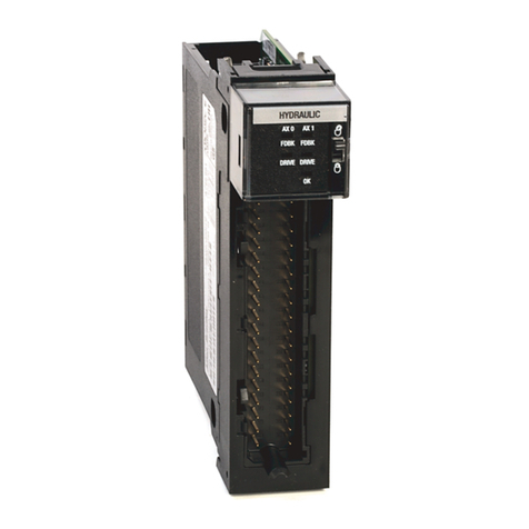
Allen-Bradley ArmorBlock 1732E-8IOLM12R Manual

Allen-Bradley

Allen-Bradley ArmorBlock 1732E-8IOLM12R Manual

Allen-Bradley CENTERLINE 1500 User manual

Allen-Bradley

Allen-Bradley CENTERLINE 1500 User manual

Allen-Bradley Guardmaster 440C-ENET User manual

Allen-Bradley

Allen-Bradley Guardmaster 440C-ENET User manual

Allen-Bradley 1757-ABRIO User manual

Allen-Bradley

Allen-Bradley 1757-ABRIO User manual

Allen-Bradley Compact 5000 User manual

Allen-Bradley

Allen-Bradley Compact 5000 User manual

Allen-Bradley 1794-IE8H User manual

Allen-Bradley

Allen-Bradley 1794-IE8H User manual

Allen-Bradley ArmorBlock 1732E-IT4IM12R User manual

Allen-Bradley

Allen-Bradley ArmorBlock 1732E-IT4IM12R User manual

Allen-Bradley ControlNet 1786-RPFS User manual

Allen-Bradley

Allen-Bradley ControlNet 1786-RPFS User manual

Allen-Bradley POINT I/O PROFIBUS 1734-APB User manual

Allen-Bradley

Allen-Bradley POINT I/O PROFIBUS 1734-APB User manual

Allen-Bradley POINT I/O 1734-ADN User manual

Allen-Bradley

Allen-Bradley POINT I/O 1734-ADN User manual

Allen-Bradley PowerFlex 755 User manual

Allen-Bradley

Allen-Bradley PowerFlex 755 User manual

Allen-Bradley POINT I/O 1734-OB2 User manual

Allen-Bradley

Allen-Bradley POINT I/O 1734-OB2 User manual

Allen-Bradley 1784-KT/B Installation and user guide

Allen-Bradley

Allen-Bradley 1784-KT/B Installation and user guide

Allen-Bradley ControlNet 1786-RPFM User manual
Allen-Bradley

Allen-Bradley ControlNet 1786-RPFM User manual

Allen-Bradley POINT I/O 1734-OB2 User manual

Allen-Bradley

Allen-Bradley POINT I/O 1734-OB2 User manual

Allen-Bradley Bulletin 160 DeviceNet User manual

Allen-Bradley

Allen-Bradley Bulletin 160 DeviceNet User manual

Allen-Bradley ArmorBlock MaXum B Series User manual

Allen-Bradley

Allen-Bradley ArmorBlock MaXum B Series User manual

Allen-Bradley 1336 PLUS II User manual

Allen-Bradley

Allen-Bradley 1336 PLUS II User manual

Allen-Bradley 1440-DYN02-01RJ User manual

Allen-Bradley

Allen-Bradley 1440-DYN02-01RJ User manual

Popular Control Unit manuals by other brands

Seitz 14A80 user manual

Seitz

Seitz 14A80 user manual

Wilo RS485 Installation and operating instructions

Wilo

Wilo RS485 Installation and operating instructions

Becker CentralControl CC41 Commissioning Instruction

Becker

Becker CentralControl CC41 Commissioning Instruction

SICK CDB650 operating instructions

SICK

SICK CDB650 operating instructions

Panduit NetKey NKP5E88M Series installation instructions

Panduit

Panduit NetKey NKP5E88M Series installation instructions

MX Options Concentric Petite Fitting instructions

MX

MX Options Concentric Petite Fitting instructions

Clean Water Systems Fleck 2510 Installation & start?up guide

Clean Water Systems

Clean Water Systems Fleck 2510 Installation & start?up guide

Fairchild FSB44104A user guide

Fairchild

Fairchild FSB44104A user guide

LEGRAND Wattstopper LMIN-104 installation instructions

LEGRAND

LEGRAND Wattstopper LMIN-104 installation instructions

PMK ATT10BNCS instruction manual

PMK

PMK ATT10BNCS instruction manual

Tektronix TDS3FFT user manual

Tektronix

Tektronix TDS3FFT user manual

Woodward easYgen Technical manual

Woodward

Woodward easYgen Technical manual

Balluff BNI EIP-502-105-R015 user guide

Balluff

Balluff BNI EIP-502-105-R015 user guide

NXP Semiconductors TWR-LS1021A Getting started

NXP Semiconductors

NXP Semiconductors TWR-LS1021A Getting started

Advantech PCM-3117 Startup manual

Advantech

Advantech PCM-3117 Startup manual

Danfoss MCO 101 manual

Danfoss

Danfoss MCO 101 manual

Moons' Lin Engineering R701P user manual

Moons'

Moons' Lin Engineering R701P user manual

Aventics RV1 operating instructions

Aventics

Aventics RV1 operating instructions

manuals.online logo
manuals.online logoBrands
  • About & Mission
  • Contact us
  • Privacy Policy
  • Terms and Conditions

Copyright 2025 Manuals.Online. All Rights Reserved.

Publication 1771Ć5.62 - November 1998
Isolated Analog Input Module
(Catalog Number 1771-IL Series D)
Use this document as a guide when installing the catalog number
1771-IL/D analog input module.
To See page
Prevent Electrostatic Discharge Below
nderstand Compliance to European nion Directives 2
nderstand Product Compatibility 3
Calculate Power Requirements 3
Determine Module Placement 3
Set the Configuration Jumpers 4
Key the Backplane Connector 4
Install the Module and Field Wiring Arm 5
Connect Wiring to the Field Wiring Arm 6
Ground the Chassis and Module 7
Configure the Module 8
For this reference information See page
Status Indicators 10
Troubleshooting 11
CSA Hazardous Information 12
Specifications 13
The isolated analog input module is sensitive to electrostatic
discharge. This module is shipped in static-shielded packaging to
guard against electrostatic discharge damage. Observe the following
precautions when handling this module.
!
ATTENTION: Electrostatic discharge can damage
integrated circuits or semiconductors if you touch
backplane connector pins. Follow these guidelines
when you handle the module:
•Touch a grounded object to discharge static potential
•Wear an approved wrist-strap grounding device
•Do not touch the backplane connector or
connector pins
•Do not touch circuit components inside the module
•If available, use a static-safe work station
•When not in use, keep the module in its original
static-shielded packaging
This icon is used when
additional information is
available in the Isolated Analog
Input Module User Manual,
publication 1771Ć6.5.128.
Installation Instructions
Contents
Prevent Electrostatic
Discharge
Allen-Bradley 1771-IL
Isolated Analog Input Module 3
5#,*$"4*/. :  /6&-#&2 
The 1771-IL/D module can be used with any 1771 I/O chassis.
Compatibility and data table use is listed below.

   ! !"

#$! %$
%
&$$
%
'(
)*
+
)*
,(( 
 
%
)
%
)
)*
+(
)*
+( -./0 -0 /0




: !     %&3 %&3 %&3  
 ' /-0"4*#,& 7*4) : : :
 ' /-0"4*#,& 7*4) : : : :
% ' /-0"4*#,& 7*4)/54 2&342*$4*/.
/ ' &342*$4&( 4/ $/-0,&-&.4"28 -/(5,& 0,"$&-&.4
Do not use this module with Cat. No. 1771-AL adapter, PLC-2/20 or
2/30 programmable controllers.
The module receives its power through the 1771 I/O power supply
and requires 1.1A at 5V (5.5 Watts) from the backplane.
Add this current to the requirements of all other modules in the I/O
chassis to prevent overloading the chassis backplane and/or
backplane power supply.
You can place your module in any I/O module slot of the I/O chassis
except for the extreme left slot. This slot is reserved for PC
processors or adapter modules.
!
ATTENTION: Do not insert or remove modules from
the I/O chassis while system power is ON. Failure to
observe this rule could result in damage to module
circuitry.
Group your modules to minimize adverse affects from radiated
electrical noise and heat. We recommend the following.
•Group analog input and low voltage dc modules away from ac
modules or high voltage dc modules to minimize electrical noise
interference.
•Do not place this module in the same I/O group with a discrete
high-density I/O module when using 2-slot addressing. This
module uses a byte in both the input and output image tables for
block transfer.
(( ($
!"
$ 1
'2$
 3($
   %.&

Isolated Analog Input Module6
5#,*$"4*/. :  /6&-#&2 
Connect your I/O devices to the field wiring arm (cat. no. 1771-WF)
shipped with the module.
!
ATTENTION: Remove power from the 1771 I/O
chassis backplane and field wiring arm before
removing or installing an I/O module.
•Failure to remove power from the backplane or
wiring arm could cause module damage, degradation
of performance, or injury.
•Failure to remove power from the backplane could
cause injury or equipment damage due to possible
unexpected operation.
.",/( /52$&
.",/( /52$&
    ! " # $!#
%& &'((') *+,
)"..&, 
)"..&, 
)"..&, 
)"..&, 
)"..&, 
)"..&, 
)"..&, 
)"..&, 
*&,% !*2*.( 2-
"4 / :!




































:
-./ )& : ' -/%5,& %/&3 ./4 3500,8 ,//0 0/7&2 +/2 ,//0 0/7&2&%
".",/( 3/52$&3 142".3-*44&23 42".3%5$&23 &4$9 //0 0/7&2 -534 #&
3500,*&% #8 4)& 53&2
+
+
–
–
5.$4*/.",
2/5.%
5.$4*/.",
2/5.%
 0  
! 0 "
Allen-Bradley 1771-IL
Isolated Analog Input Module 13
5#,*$"4*/. :  /6&-#&2 
 !
5-#&2 /' .0543  '5,,8 *3/,"4&% %*''&2&.4*",
/%5,& /$"4*/.  !( 2"$+ :  3,/4
.054 6/,4")& 2".)&3 1./-*.",7 9 4/ 9; 
 4/ ; 
: 4/ 9; 
: 4/ 9; 
.054 $522&.4 2".)&3 1./-*.",7 9 4/ 9-
 4/ 9-
: 4/ 9-
&3/,54*/. :#*4 #*."28 /6&2 '5,, 2".)&
$$52"$8 ;/,4")&
522&.4
80*$", : < /' '5,, 3$",& 2".)& = /
">*-5- : < /' '5,, 3$",& 2".)& = /
80*$", : < /' '5,, 3$",& 2".)& = /
">*-5- : < /' '5,, 3$",& 2".)& = /
1.$,5%&3 < ?@&. 53*.) *.4&2.", $522&.4 2&3*34/27
&-0&2"452& /&''*$*&.4 900-!/ /' '5,, 3$",& 2".)&
*.&"2*48 9 
&0&"4"#*,*48 9 
3/,"4*/. ;/,4")& @*3 *3/,"4*/. -&&43 /2 &>$&&%3 4@& 2&A5*2&-&.43 /' B
34".%"2%  ".%  34".%"2%  / 
.054 /6&26/,4")& 02/4&$4*/. 6/,4")& -/%&C ; "$ 12-37 $/.4*.5/53D
$522&.4 -/%&C ; %$ $/.4*.5/53
B.3$",&%  ".% #*."28 /54054
%"4" 4/ 4@& 02/$&33/2
 4/ 9 '/2 5.*0/,"2 2".)&3
1 4/ ; 9 4/ 9;  4/ 9- ".% 9 4/ 9-7
: 4/  '/2 #*0/,"2 2".)&3
9; 9; 9- *.054 2".)&3
.054 *-0&%".$& E -&)/@-3 '/2 6/,4")& 2".)&3D  /@-3 '/2 $522&.4
2".)&3
/--/. -/%& 2&F&$4*/. E %# = G ".%  /@- 3/52$& *-#",".$&
/--/. -/%& *-0&%&.$& E -&)/@-3 [email protected]&% #8 H .
/2-", -/%& 2& &$4*/. ! %# ' 9
(0&. *2$5*4 &4&$4*/. )/,4"+& -/%&
522&.4 -/%&
(0&. *.054 02/%5$&3 503$",& 2&"%*.+
(0&. *.054 02/%5$&3 9&2/ 2&"%*.+
*-& 4/ &4&$4 (0&. *2$5*4 3 -"1*-5-
",*#2"4*/. 54/:$",*#2"4*/. 6/773&4 ".% +"*.8
;&2/ /773&4 ".% +"*. "% 534-&.4 7/2 &"$< $<"..&, =*"
02/+2"--*.+ 4&2-*.",
)&2*7> &=&2> 3*1 -/.4<3 4/ -"*.4"*. 30&$*7*&% "$$52"$>
.+*.&&2*.+ 5.*43 3&.4 4/
02/$&33/2
?  @*4< 3&,&$4"#,& 3$",*.+
? #*."2>
.4&2.", 3$". 2"4& -3 7/2  $<"..&,3
"$A0,".& 522&.4  ' ?)
/@&2 *33*0"4*/.  B"443 -"1*-5-
<&2-", *33*0"4*/.  CD<2 -"1*-5-
/.%5$4/23 B*2*.+
"4&+/2>
"#,&
 +"5+& 342".%&% 6-"18
D *.$< *.35,"4*/. 6-"18
"4&+/2> 
C3& &,,%&.  3<*&,%&% $"#,&
  !  " 

Isolated Analog Input Module14
5#,*$"4*/. :  /6&-#&2 
!
.6*2/.-&.4", /.%*4*/.3
0&2"4*/.", &-0&2"452&!
4/2"(& &-0&2"452&!
&,"4*6& 5-*%*48! 0&2"4*.(
4/2"(&
 4/ _ ' 4/ _)
: 4/ _ ': 4/ _
 4/ + '7*41/54 $/.%&.3"4*/.)
 4/ + '7*41/54 $/.%&.3"4*/.)
&8*.( #&47&&.  ".% 
#&47&&.  ".% 
*&,% 9*2*.( 2- "4 / :9
9*2*.( 2- $2&7 /2;5& : *.$1:0/5.%3
(&.$8 &24*<*$"4*/.
'71&. 02/%5$4 /2 0"$="(*.( *3 -"2=&%)
• $&24*<*&%
• ,"33  *6*3*/.  2/503     $&24*<*&%
•>? ,*34&%
• -"2=&% </2 ",, "00,*$"#,& %*2&$4*6&3
>3&2 ".5", 5#,*$"4*/. :
&<&2 4/ 05#,*$"4*/. : @2/(2"--"#,& /.42/,,&2 9*2*.( ".% 2/5.%*.( 5*%&,*.&3A
Allen-Bradley 1771-IL
Isolated Analog Input Module 15
5#,*$"4*/. :  /6&-#&2 
The following are major differences between series levels of the
1771-IL isolated analog input module.
   !   "  
"4" "#,& 3"(&  *.! /54! 2&"% 7/2%3! 72*4&
7/2%3
 *.! /54! 2&"% 7/2%3! 72*4& 7/2%3
&3/,54*/. :#*4 #*."28 :#*4 #*."28
"-0,& *-& /  &'"5,4 -3) 2".(&
-3 4/ 3 *. -3 *.$2&-&.43
/  &'"5,4 -3) 2".(& -3 4/ 3 *. -3 *.$2&-&.43
",*#2"4*/. &$+".*$", "%1534-&.43 '/2 ("*.
/''3&4 ".% 9&2/ /''3&4
54/:$",*#2"4*/. ;/''3&4 ".% ("*.<
=&2/ /''3&4 ".% ("*. "%1534-&.4 '/2 &"$+ $+"..&, 6*" 02/(2"--*.(
4&2-*.",
$$52"$8 > /' '5,, 3$",& 2".(& ? / @/,4"(&A 80*$", : > /' '5,, 3$",& 2".(& ? /
"B*-5- : > /' '5,, 3$",& 2".(& ? /
522&.4A 80*$", : > /' '5,, 3$",& 2".(& ? /
"B*-5- : > /' '5,, 3$",& 2".(& ? /
;.$,5%&3 > 7+&. 53*.( *.4&2.", $522&.4 2&3*34/2<
/--/. /%& &1&$4*/. C %# ? 9 ".%  /+- 3/52$&
*-#",".$&
C %# ? 9 ".%  /+- 3/52$& *-#",".$&
/2-", -/%& 2&1&$4*/. C %# ? 9 C %# ? 9
.054 D6&26/,4"(& 2/4&$4*/. E@ 0&"F $/.4*.5/53 6/,4"(& -/%&A @ "$ ;2-3< $/.4*.5/53)
$522&.4 -/%&A @ %$ $/.4*.5/53
"$F0,".& 522&.4  ? E@  ? E@  ? E@
/7&2 *33*0"4*/.  G"443 -"B*-5-  G"443 -"B*-5-  G"443 -"B*-5-
+&2-", *33*0"4*/.   !+2 -"B*-5-   !+2 -"B*-5-   !+2 -"B*-5-
.34&2.", $". "4& -3 '/2  $+"..&,3 ;./ 3$",*.( /2
%*(*4", '*,4&2*.(<
-3 '/2  $+"..&,3 ;./ 3$",*.( /2 %*(*4", '*,4&2*.(<
.(*.&&2*.( .*43 3&.4 4/
2/$&33/2
E  7*4+ 3&,&$4"#,& 3$",*.( E  7*4+ 3&,&$4"#,& 3$",*.(
E #*."28
(&.$8 &2'*'*$"4*/.  $&24*'*&%
 ,"33  *6*3*/.  2/503     $&24*'*&%)
H ,*34&%
 $&24*'*&%
 ,"33  *6*3*/.  2/503
    $&24*'*&%)
H ,*34&%)
 -"2F&% '/2 ",, "00,*$"#,&
%*2&$4*6&3
 !#
 $  !$ 
 "  