manuals.online logo
Brands
  1. Home
  2. •
  3. Brands
  4. •
  5. Altrad
  6. •
  7. Construction Equipment
  8. •
  9. Altrad AFBM 160 User manual

Altrad AFBM 160 User manual

WARRANTY CERTIFICATE
AFBM 160
WARRANTY DECLARATION
We hereby declare:
That the product will perform seamlessly during the warranty period if the obstructions are observed.
That the service and necessary spare parts for the products will be provided within the warranty period as well as 5 years
after its expiry.
That during the warranty period, we will repair the product within 45 days at the latest at our own expense, which also
includes transport costs for the products that is the subject of the complaint.
If the mixer is not repaired in the aforementioned deadline, it will be replaced by a new one at your request. Transport costs
cannot exceed the valid costs of rail transport or mailing via postal services. The warranty becomes valid on th
e day of purchase,
which is verified with a confirmed warranty certificate and a confirmed receipt. If the product is repaired, the warranty per
iod is
extended by the duration of the repair. Please provide the following information when notifying us of a malfunction: product
designation and type, date of purchase, description of the malfunction, and the exact address.
THE WARRANTY PERIOD is 12 months.
The warranty will be void:
If the usage of the mixer is incorrect or non
-
approved, or if the mixer is
overloaded.
If the manufacturer’s written instructions are not observed.
If repairs are completed by an unauthorized person without the manufacturer’s consent.
The warranty for products is valid in the geographical area of the country in which the product
was sold.
WARRANTY PROVIDER PRODUCT SELLER
Altrad Fort BV ______________________
SimonStevinstraat 6 ______________________
4004 JV Tiel ______________________
Nederland ______________________
DATE OF HANDOVER PRODUCT
IDENTIFICATION
_________________
____________________
4
Altrad Fort BV.
Simon Stevinstraat 6, 4004 JV Tiel
The Netherlands
tel.: +31 344 638 484 / [email protected]
www.altradfort.nl
DECLARATION OF CONFORMITY
Based on the European Community Machinery Directive 2006/42/EC, on
the Electromagnetic Compatibility Directive 2006/108/EC, on the Low
Voltage Directive 2006/95/EC, and the Noise Directive 2000/14/EC.
Altrad Fort BV
Simon Stevinstraat 6
4004 JV Tiel
The Netherlands
declares under its sole responsibility that during the development,
construction and production of
the AFBM 160 concrete mixer
the following standards were met:
2006/42/EC
EN 12151:2007, EN 60204-1:2006+2009+AC:2010 EN
60335-1:2012+AC:2014+A11:2014
EN 62233:2008+AC:2008
Director: H. Lindemann
DEAR CUSTOMER!
You have purchased a new concrete mixer. Our many years of experience
are an assurance that you have made the right choice. We have ensured a
high-quality production meeting strict European regulations, which ensure a
safe operation if these instructions are observed.
The mixer is intended for mixing construction materials.
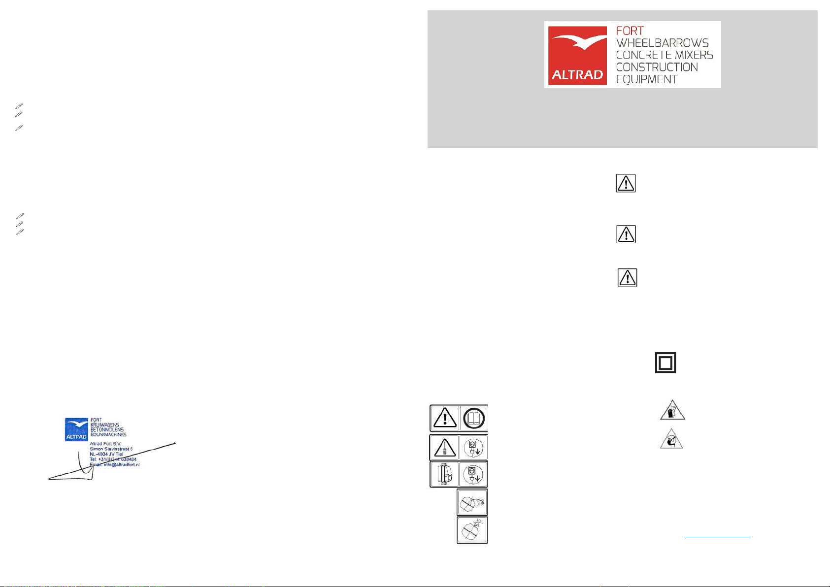
EXPLANATION OF SYMBOLS ON THE MIXER
Before use, please read the operating
instructions for the mixer.
Before every repair, do not forget to unplug
the mixer from the electrical grid.
Before removing the cabinet cover, do not
forget to unplug the mixer from the electrical
grid.
The lubrication of drive gears is prohibited
at all times.
Reaching into a rotating drum is
dangerous and therefore prohibited.
Version 1.0
The observance of instructions and recommendations for the operation
and maintenance ensures safe operation and a long service life of the
mixer.
Electrical Safety
The mixer is manufactured according to the applicable regulations.
Double insulation ensures complete protection against electrical shock
therefore the product can be connected to the electrical grid without extra
protection. This applies only to the single-phase motor.
Mechanical Safety
During the construction of the mixer, we have ensured complete safety of
the operator. All the dangerous spots are protected or constructed in order
to prevent injury.
Safety Warnings
Do not remove any protection ele
ments from the mixer because they ensure a safe
operation.
The cabinet of the electrical motor shall be closed during operation. Reaching
into a rotating drum is prohibited. The power cable must not be
damaged. Lay the cable so that any damage will be prevented
during operation. Make sure not to place the mixer on the cable. The drum
can only be filled and emptied when it is rotating. The mixer can
only be started if the drum is empty. Do not use the mixer in an
explosive atmosphere. During operation (rotating of the drum), the mixer must not
move.
CAUTION! Double insulation machine
(applies only to the single-phase
motor)
During all repairs, original parts must be used in order to provide a
double insulation also after the repair!
CAUTION!
Workplace materials
inhalation hazard
CAUTION! Mandatory use of
personal protective equipment
MIXER STORAGE
The mixer is stored in rooms with minimal risks for damage. Longer storage
periods require an enclosed and dry room. For shorter storage periods, no
special room is required. The storage temperature can be in the range
between -30°C and +50°C.
INSTRUCTIONS FOR DISPOSAL OF PRODUCT AND ITS
PACKAGING AFTER SERVICE LIFE
We recommend that you submit the product after the expiry of its service life
to authorized organizations for the collection of secondary metals.
Website: http://www.altradfort.nl/
EN
1
TECHNICAL DATA
Mixer type
AFBM 160
Dimensions
height (mm)
1340
folded height (mm)
870
length (mm)
1140
width (mm)
720
Mixer weight
(kg) 60
Operating capacity
(l) 145-150
Voltage (alternating)
(V) 230
Rated power (S6 10%)
(W) 700
Rated current
(A) 2.7
Mixer noise emissions (empty)
(dBA)
86
PREPARATION OF THE MIXER FOR OPERATION
1. MIXER ASSEMBLY
The mixer is folded at delivery. Before startup, lift it into the operating position. After the packaging
has been removed, loosen the nuts (4). First, hold the mixer by the cabinet (33), lift it and at the same time open the
wheel assembly (5) and fix it. Then, lift the mixer from the front. Grab it by the handle (9) and extend the support
leg (1) during the lifting move. Make sure that the mixer does not collapse. After the mixer has been setup in the
operating position, tighten the nuts
(4). The assembly needs to be performed carefully otherwise the mixer could collapse when loaded or transported.
2. ELECTRICAL CONNECTION OF THE MIXER
Connect the mixer to the electrical grid with a cable that has a minimum cross-section of 3×1.5mm2. This cross-section
is suitable up to the length of 25m. If the power cable is longer, the cross-section must be 3×2.5mm2. The socket for
the connection of the mixer must be equipped with a 10A fuse. No additional electrical motor protection is necessary
since the motor has an integrated thermal sensor. The sensor is connected to the switch that automatically stops the
operation of the electrical motor in case of overheating.
3. MIXER OPERATION
Place the mixer on level and firm ground to prevent sinking or
capsizing.
The maximum slope of the ground is 10° as shown on the picture
below. The acceptable slope of 10° means the deviation of the
water level 88mm from the edge of the cabinet.
Connect the product to the el
ectrical grid with an undamaged extension cord that must be extended and laid in
order to prevent damage.
Start the mixer with the switch that can only be turned on if there is voltage on the terminals. Every time the electrical
current is interrupted, the switch is turned off. If you wish to restart the mixer, push the start button again every time the
voltage is restored. Place the mixer drum into the position suitable for the material you wish to mix (more vertically for
mortar, more horizontally for concrete). After this operation has been completed, the drum can be filled. Only fill the drum
up to its maximum operating capacity.
We suggest the following order of filling: First, pour part of the water into the drum, add half of the sand and all the
additional material (such as cement, lime...). After the contents have been mixed slightly, add the remaining water and
sand.
WARNING: After the first couple of mixing cycles, water can start leaking at the joint between the cover and
bottom of the vessel.
Only a rotating drum can be filled and emptied! The mixer can be transported within the construction site by means
of wheels and a handle. During transport, the drum opening must face upwards.
In order to ensure complete operational
safety, please also observe the instructions of the manufacturers of additional materials (cement, lime, etc.).
4. CLEANING AND MAINTENANCE
Before every cleaning or repair, do not forget to
unplug the mixer from the electrical grid
Cleaning extends the service life of the mixer therefore it must be as thorough as possible. Wash the external surfaces
of the mixer with flowing water and a soft brush. Do not scratch the mortar with sharp objects as you might damage the
coated surfaces. Rinse the inside of the drum immediately after work with a pressurized water jet in order to remove all
the remains of the mixed material.
The mixer maintenance is simple and reduced to a minimum:
Periodically check if the bolts and nuts are tightened sufficiently
Regularly check the tension of the drive belt and re-tension it if necessary. Re-tension it by loosening the two nuts on
the bolts used to attach the electrical motor cabinet to the frame and pushing the electrical motor together with the
cabinet down. Tighten the nuts. Only qualified persons with original spare parts can perform any repairs of the mixer.
MIXER COMPONENTS
1. Sprocket M00040
2. Drum PL00066
3. Cover M000439
4. Bearing M000115
5. Bolt M8×70 M000301
6. Turning wheel PL00119
7. Nut M12 M000137
8. Pipe clamp PL00060
9. Nut M8 M000131
10. Bolt M12×45 M000343
11. Brake M000344
12. Spring M000417
13. Brake rope M000324
14. Nut M12 M000137
15. Pedal M000375
16. Bolt M12×90 M000312
17. Cover M000435
18. Retaining ring z48 M000329
19. Bearing M000115
20. Crossbar PL00099
21. Bolt M000285
22. Cogwheel M000443
23. Switch M000242
24. Bearing M000114
25. Spring pin ø 6×45 M000278
26. Bearing M000114
27. Spring pin ø 6×45 M000332
28. Cabinet M000434
29. Drive shaft PL00055
30. Belt M000099
31. Pulley M000430
32. Retaining ring M000326
33. Cover M000436
34. Bolt M000434
35. Electric motor M000150
36. Bolt PL00062
37. Bolt M8×70 M000301
38. Framework PL00102
39. Wheel M000355
40. Axle guard M000278
2
3

Other Altrad Construction Equipment manuals

Altrad Belle Maxi 140 User manual

Altrad

Altrad Belle Maxi 140 User manual

Altrad BELLE TDX 650A User manual

Altrad

Altrad BELLE TDX 650A User manual

Altrad BELLE TDX 650A User manual

Altrad

Altrad BELLE TDX 650A User manual

Altrad BELLE EASY SCREED PRO User manual

Altrad

Altrad BELLE EASY SCREED PRO User manual

Altrad BELLE MINIMIX 150E+ User manual

Altrad

Altrad BELLE MINIMIX 150E+ User manual

Altrad BELLE RPC 60/80 User manual

Altrad

Altrad BELLE RPC 60/80 User manual

Altrad BELLE RPC 45 User manual

Altrad

Altrad BELLE RPC 45 User manual

Altrad BELLE PREMIER XT User manual

Altrad

Altrad BELLE PREMIER XT User manual

Altrad BELLE MINIMIX 150E+ User manual

Altrad

Altrad BELLE MINIMIX 150E+ User manual

Altrad BELLE VIBRATECH+ 38 User manual

Altrad

Altrad BELLE VIBRATECH+ 38 User manual

Altrad BELLE PORTO SCREED User manual

Altrad

Altrad BELLE PORTO SCREED User manual

Altrad DRAG BOX User manual

Altrad

Altrad DRAG BOX User manual

Altrad BELLE BMD 300 User manual

Altrad

Altrad BELLE BMD 300 User manual

Altrad BELLE MPC 300 User manual

Altrad

Altrad BELLE MPC 300 User manual

Altrad BELLE PCEL 320X User manual

Altrad

Altrad BELLE PCEL 320X User manual

Altrad BELLE PCX 20/45 User manual

Altrad

Altrad BELLE PCX 20/45 User manual

Altrad ATIKA RLC 40-10 User manual

Altrad

Altrad ATIKA RLC 40-10 User manual

Altrad BET GN 180 User manual

Altrad

Altrad BET GN 180 User manual

Altrad BGA Series User manual

Altrad

Altrad BGA Series User manual

Altrad MK II PODIUM User manual

Altrad

Altrad MK II PODIUM User manual

Altrad BELLE PCLX 16/45E User manual

Altrad

Altrad BELLE PCLX 16/45E User manual

Altrad Belle BGN+ User manual

Altrad

Altrad Belle BGN+ User manual

Altrad BELLE TDX 650 A ROLLER User manual

Altrad

Altrad BELLE TDX 650 A ROLLER User manual

Altrad Belle TDX 650 User manual

Altrad

Altrad Belle TDX 650 User manual

Popular Construction Equipment manuals by other brands

Belle RPC 45/60 Operator's manual

Belle

Belle RPC 45/60 Operator's manual

Trelawny MHS 5 operation & maintenance

Trelawny

Trelawny MHS 5 operation & maintenance

EZG Grout Hog GPH75 owner's manual

EZG

EZG Grout Hog GPH75 owner's manual

NARGESA CC60 Instruction book

NARGESA

NARGESA CC60 Instruction book

Doka 150F Instructions for assembly and use

Doka

Doka 150F Instructions for assembly and use

MUYEN VA121 quick start guide

MUYEN

MUYEN VA121 quick start guide

Megger Easyloc Standard RxTx operating instructions

Megger

Megger Easyloc Standard RxTx operating instructions

zarges Z200 Assembly and usage instructions

zarges

zarges Z200 Assembly and usage instructions

probst STS-33 operating instructions

probst

probst STS-33 operating instructions

Ulma MK Structure user guide

Ulma

Ulma MK Structure user guide

Fayat Group DYNAPAC CC224HF instruction manual

Fayat Group

Fayat Group DYNAPAC CC224HF instruction manual

RGC HS1000 instructions

RGC

RGC HS1000 instructions

Manitowoc 14000 Operator's manual

Manitowoc

Manitowoc 14000 Operator's manual

HYVA Amco Veba 816N WARNING, OPERATING AND MAINTENANCE MANUAL

HYVA

HYVA Amco Veba 816N WARNING, OPERATING AND MAINTENANCE MANUAL

New Holland 1650M Tier 2 Service manual

New Holland

New Holland 1650M Tier 2 Service manual

Precision Manufacturing Inc. TeleClipper TC6451 Assembly instructions

Precision Manufacturing Inc.

Precision Manufacturing Inc. TeleClipper TC6451 Assembly instructions

Dynapac CA 602 maintenance

Dynapac

Dynapac CA 602 maintenance

Ulma TFS100 manual

Ulma

Ulma TFS100 manual

manuals.online logo
manuals.online logoBrands
  • About & Mission
  • Contact us
  • Privacy Policy
  • Terms and Conditions

Copyright 2025 Manuals.Online. All Rights Reserved.