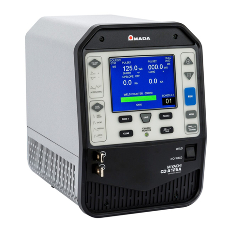
Amada 125ADP User manual

990-922 Rev G
STORED ENERGY POWER SUPPLY
125/300/1000ADP
OPERATION MANUAL

125ADP/300ADP/1000ADP DUAL PULSE RESISTANCE WELDING POWER SUPPLY
ii 990-922
Copyright © 2012-2017 Amada Miyachi America
The engineering designs, drawings and data contained herein are the proprietary work of
Amada MiyachiAmerica and may not be reproduced, copied, exhibited or otherwise used
without the written authorization of Amada Miyachi America.
Printed in the United States of America.
Revision Record
Revision EO Date Basis of Revision
A 42027 06/12 None. Original edition.
B 42170 09/12
Add Repeat Mode function and 125ADP Ws programming in
0.1 Ws increments.
C 42840 10/13 Update to Miyachi America name and logo.
D 43480 11/14 Updated to Amada Miyachi America name and log.
E 43808 07/15 Updated to Amada format.
F 44033 01/16 Update J6 & J7 I/O schematics
G 44642 05/17 Update Footswitch + Binary Input Selection
Your New ADP Welder Shipment Contains The Following Items:
1. The ADP unit.
2. User manual # 990-922.
3. Ship Kit # 4-81179-01.
4. External current coil (1000ADP only).
NOTE: The 1000ADP will also have an external transformer shipped on a separate pallet.
Ship Kit Contents
Ship Kit Part Number 4-81179-01
Amada Miyachi America
Part Number Description Quantity
205-129 Power Cord, 115 VAC 1
245-162 Backshell, 37 pin D-sub 1
250-409 D-sub, 37 pin connector 1

125ADP/300ADP/1000ADP DUAL PULSE RESISTANCE WELDING POWER SUPPLY
990-922 iii
CONTENTS
Revision Record ......................................................................................................................................... ii
Contact Us .............................................................................................................................................. vi
Safety Notes ............................................................................................................................................. vii
Chapter 1. Description
Section I: Features ..................................................................................................................................1-1
Features ............................................................................................................................................1-1
Display Screens ...............................................................................................................................1-2
Description .......................................................................................................................................1-4
Section II: Major Components ...............................................................................................................1-5
Major Components ..........................................................................................................................1-5
Front Panel Controls ........................................................................................................................1-5
UP/DOWN Buttons ..................................................................................................................1-6
Polarity Select ...........................................................................................................................1-7
Pulse Select ...............................................................................................................................1-7
RUN ..........................................................................................................................................1-7
MENU ......................................................................................................................................1-7
LIMITS / COUNTERS .............................................................................................................1-8
Pulse 1 & Pulse 2 ......................................................................................................................1-8
SQZ / HOLD ............................................................................................................................1-8
SAVE ........................................................................................................................................1-8
CLEAR .....................................................................................................................................1-8
CHARGE MONITOR Light ....................................................................................................1-9
WELD/NO WELD Switch ..............................................................................................................1-9
Emergency Stop Switch Operation ..................................................................................................1-9
Chapter 2. Installation and Setup
Section I: Installation .............................................................................................................................2-1
Unpacking ........................................................................................................................................2-1
Space Requirements .........................................................................................................................2-1
Utilities ............................................................................................................................................2-2
Power ........................................................................................................................................2-2
Compressed Air and Cooling Water .........................................................................................2-3
Input Logic Configuration ...............................................................................................................2-3
Section II. 125ADP & 300ADP External Equipment Connections ....................................................... 2-4
Emergency Stop Switch ...........................................................................................................2-4
Weld Head Connections to Power Supply Terminals ..............................................................2-5
Foot Pedal-Actuated Weld Head Connection ...........................................................................2-6
EZ-AIR Weld Head Connections .............................................................................................2-7
24 VDC EZ-AIR ................................................................................................................2-7
24 VAC EZ-AIR ................................................................................................................ 2-8

125ADP/300ADP/1000ADP DUAL PULSE RESISTANCE WELDING POWER SUPPLY
iv 990-922
CONTENTS (Continued) Page
Section III. 1000ADP External Equipment Connections ....................................................................2-10
Overview ........................................................................................................................................2-10
Connecting the 1000ADP Transformer .........................................................................................2-11
Chapter 3. Using Display Screens
Section I: RUN Screen ...........................................................................................................................3-1
RUN Screen .....................................................................................................................................3-2
Editing the RUN Screen ..................................................................................................................3-2
Pulse 1 ......................................................................................................................................3-2
Pulse 2 ......................................................................................................................................3-2
Squeeze Time ...........................................................................................................................3-2
Hold Time .................................................................................................................................3-3
Section II: LIMITS / COUNTERS screen ............................................................................................. 3-4
LIMITS / COUNTERS Screen ........................................................................................................3-4
Edit the LIMITS / COUNTERS Screen ..........................................................................................3-4
Pulse 1 – Upper Limit................................................................................................................3-4
Pulse 1 – Lower Limit...............................................................................................................3-4
Pulse 2 Limits ...........................................................................................................................3-4
Pulse 1 – Action.........................................................................................................................3-5
Reset Weld Counter ..................................................................................................................3-5
Edit Counter Limit ....................................................................................................................3-5
Section III: MENU Screen .....................................................................................................................3-7
MENU Screen ..................................................................................................................................3-7
Editing the MENU Screen ...............................................................................................................3-7
Baud Rate .................................................................................................................................3-8
Debounce ..................................................................................................................................3-8
Chaining Start ...........................................................................................................................3-8
Chaining End ............................................................................................................................3-9
Remote ......................................................................................................................................3-9
Language ..................................................................................................................................3-9
Reset Defaults .........................................................................................................................3-10
Fast Welding ...........................................................................................................................3-10
Repeat Mode ...........................................................................................................................3-11
Repeat Time ............................................................................................................................3-12
Chapter 4. Operating Instructions
Section I: Introduction ...........................................................................................................................4-1
Before You Start .............................................................................................................................. 4-1
Pre-Operational Checks ...................................................................................................................4-1
Connections ..............................................................................................................................4-1
Power ........................................................................................................................................4-1
Compressed Air ........................................................................................................................4-1
Initial Setup ......................................................................................................................................4-2

125ADP/300ADP/1000ADP DUAL PULSE RESISTANCE WELDING POWER SUPPLY
990-922 v
Page
Section II. Operation ..............................................................................................................................4-3
Start-Up ............................................................................................................................................4-3
Use Existing Weld Schedules ..........................................................................................................4-3
Modifying Weld Schedules .............................................................................................................4-3
Set Peak Current Monitor limits ......................................................................................................4-4
Set Weld Counter Limits or Reset the Weld Counter. .....................................................................4-5
Set MENU Entries ...........................................................................................................................4-5
Dual Weldhead Operation ...............................................................................................................4-6
Programming Lock ..........................................................................................................................4-6
Schedule Lock .................................................................................................................................4-7
Fast Welding ....................................................................................................................................4-7
Turning the Unit OFF ......................................................................................................................4-7
Section III: Operational Notes ...............................................................................................................4-8
Repetition Rate ................................................................................................................................4-8
Automatic Power Turn-Down .........................................................................................................4-8
Open Load Protection ......................................................................................................................4-8
Extended Shut-down Procedure ......................................................................................................4-9
Chapter 5. Maintenance
Section I. Troubleshooting .....................................................................................................................5-1
Troubleshooting ...............................................................................................................................5-1
Error Messages ................................................................................................................................5-2
Section II. Maintenance .........................................................................................................................5-4
Calibration .......................................................................................................................................5-4
Electrode Maintenance ....................................................................................................................5-4
Parts Replacement ...........................................................................................................................5-4
Section III. Repair Service .....................................................................................................................5-5
Appendix A. Technical Specifications ................................................................................................. A-1
Appendix B. Electrical and Data Connections ......................................................................................B-1
Appendix C. System Timing ..................................................................................................................C-1
Appendix D. Communications .............................................................................................................. D-1
Appendix E. The Basics of Resistance Welding ...................................................................................E-1
Appendix F. Quality Resistance Welding Solutions: Defining the Optimum Process .........................F-1

125ADP/300ADP/1000ADP DUAL PULSE RESISTANCE WELDING POWER SUPPLY
vi 990-922
CONTACT US
Thank you for purchasing a Miyachi Unitek™ Resistance Welding System Control.
Upon receipt of your equipment, please thoroughly inspect it for shipping damage prior to its
installation. Should there be any damage, please immediately contact the shipping company to file a
claim, and contact us at:
Amada Miyachi America
1820 South Myrtle Avenue
P.O. Box 5033
Monrovia, CA 91017-7133
TELEPHONE: (626) 303-5676
e-mail: [email protected]
The purpose of this manual is to provide the information required for proper and safe operation and
maintenance of the Miyachi Unitek™ 125ADP/300ADP/1000ADP Dual Pulse Resistance Welding
Power Supplies.
We have made every effort to ensure that information in this manual is both accurate and adequate. If
you have any questions or suggestions to improve this manual, please contact us at the phone number or
addresses above.
Amada Miyachi America is not responsible for any loss or injury due to improper use of this product.

125ADP/300ADP/1000ADP DUAL PULSE RESISTANCE WELDING POWER SUPPLY
990-922 vii
SAFETY NOTES
DANGER
DEATH ON CONTACT may result if you fail to observe all safety
precautions. Lethal voltages are present in the Power Supply.
Never perform any welding operation without wearing protective safety glasses.
This instruction manual describes how to operate, maintain and service the 125ADP/300ADP/1000ADP
Dual Pulse Resistance Welding Power Supplies, and provides instructions relating to its safe use. A
separate manual provides similar information for the weld head used in conjunction with the power
supply. Procedures described in these manuals must be performed, as detailed, by qualified and trained
personnel.
For safety, and to effectively take advantage of their full capabilities, please read these instruction
manuals before attempting to operate weld heads and power supplies.
Procedures other than those described in these manuals or not performed as prescribed in them, may
expose personnel to electrical shock or burn hazards.
After reading these manuals, keep them for future reference.
Please note the following conventions used in this manual:
WARNING:Comments marked this way warn the reader of conditions which might result in
immediate death or serious injury.
CAUTION:Comments marked this way warn the reader of conditions which might result in damage to
the equipment.

125ADP/300ADP/1000ADP DUAL PULSE RESISTANCE WELDING POWER SUPPLY
viii 990-922

125ADP/300ADP/1000ADP DUAL PULSE RESISTANCE WELDING POWER SUPPLY
990-922 ix

125ADP/300ADP/1000ADP DUAL PULSE RESISTANCE WELDING POWER SUPPLY
x 990-922
LIMITED WARRANTY
1. (a) Subject to the exceptions and upon the conditions set forth herein, Seller warrants to Buyer that
for a period of one (1) year from the date of shipment (“Warranty Period”), that such Goods will be free
from material defects in material and workmanship.
(b) Notwithstanding the foregoing and anything herein to the contrary, the warranty set forth in this
Section 1 shall be superseded and replaced in its entirety with the warranty set forth on Exhibit A
hereto if the Goods being purchased are specialty products, which include, without limitation, laser
products, fiber markers, custom systems, workstations, Seller-installed products, non-catalogue
products and other custom-made items (each a “Specialty Products.”
(c) EXCEPT FOR THE WARRANTY SET FORTH IN SECTION 1(A), SELLER MAKES NO
WARRANTY WHATSOEVER WITH RESPECT TO THE GOODS (INCLUDING ANY SOFTWARE) OR
SERVICES, INCLUDING ANY (a) WARRANTY OF MERCHANTABILITY; (b) WARRANTY OF
FITNESS FOR A PARTICULAR PURPOSE; (c) WARRANTY OF TITLE; OR (d) WARRANTY
AGAINST INFRINGEMENT OF INTELLECTUAL PROPERTY RIGHTS OF A THIRD PARTY;
WHETHER EXPRESS OR IMPLIED BY LAW, COURSE OF DEALING, COURSE OF
PERFORMANCE, USAGE OF TRADE OR OTHERWISE.
(d) Products manufactured by a third party and third party software (“Third Party Product”) may
constitute, contain, be contained in, incorporated into, attached to or packaged together with, the
Goods. Third Party Products are not covered by the warranty in Section 1(a). For the avoidance of
doubt, SELLER MAKES NO REPRESENTATIONS OR WARRANTIES WITH RESPECT TO ANY
THIRD PARTY PRODUCT, INCLUDING ANY (a) WARRANTY OF MERCHANTABILITY; (b)
WARRANTY OF FITNESS FOR A PARTICULAR PURPOSE; (c) WARRANTY OF TITLE; OR (d)
WARRANTY AGAINST INFRINGEMENT OF INTELLECTUAL PROPERTY RIGHTS OF A THIRD
PARTY; WHETHER EXPRESS OR IMPLIED BY LAW, COURSE OF DEALING, COURSE OF
PERFORMANCE, USAGE OF TRADE OR OTHERWISE. Notwithstanding the foregoing, in the event
of the failure of any Third Party Product, Seller will assist (within reason) Buyer (at Buyer’s sole
expense) in obtaining, from the respective third party, any (if any) adjustment that is available under
such third party’s warranty.
(e) Seller shall not be liable for a breach of the warranty set forth in Section 1(a) unless: (i) Buyer gives
written notice of the defect, reasonably described, to Seller within five (5) days of the time when Buyer
discovers or ought to have discovered the defect and such notice is received by Seller during the
Warranty Period; (ii) Seller is given a reasonable opportunity after receiving the notice to examine such
Goods; (iii) Buyer (if requested to do so by Seller) returns such Goods (prepaid and insured to Seller at
1820 South Myrtle Avenue, Monrovia, CA 91016or to such other location as designated in writing by
Seller) to Seller pursuant to Seller’s RMA procedures and Buyer obtains a RMA number from Seller
prior to returning such Goods for the examination to take place; and (iii) Seller reasonably verifies
Buyer’s claim that the Goods are defective and that the defect developed under normal and proper use.
(f) Seller shall not be liable for a breach of the warranty set forth in Section 1(a) if: (i) Buyer makes any
further use of such Goods after giving such notice; (ii) the defect arises because Buyer failed to follow
Seller’s oral or written instructions as to the storage, installation, commissioning, use or maintenance of
the Goods; (iii) Buyer alters or repairs such Goods without the prior written consent of Seller; or (iv)
repairs or modifications are made by persons other than Seller’s own service personnel, or an
authorized representative’s personnel, unless such repairs are made with the written consent of Seller
in accordance with procedures outlined by Seller.

125ADP/300ADP/1000ADP DUAL PULSE RESISTANCE WELDING POWER SUPPLY
990-922 xi
(g) All expendables such as electrodes are warranted only for defect in material and workmanship
which are apparent upon receipt by Buyer. The foregoing warranty is negated after the initial use.
(h) Subject to Section 1(e) and Section 1(f) above, with respect to any such Goods during the Warranty
Period, Seller shall, in its sole discretion, either: (i) repair or replace such Goods (or the defective part)
or (ii) credit or refund the price of such Goods at the pro rata contract rate, provided that, if Seller so
requests, Buyer shall, at Buyer’s expense, return such Goods to Seller.
(i) THE REMEDIES SET FORTH IN SECTION 1(H) SHALL BE BUYER’S SOLE AND EXCLUSIVE
REMEDY AND SELLER’S ENTIRE LIABILITY FOR ANY BREACH OF THE LIMITED WARRANTY
SET FORTH IN SECTION 1(A). Representations and warranties made by any person, including
representatives of Seller, which are inconsistent or in conflict with the terms of this warranty, as set
forth above, shall not be binding upon Seller.

125ADP/300ADP/1000ADP DUAL PULSE RESISTANCE WELDING POWER SUPPLY
xii 990-922
Exhibit A
Warranty for “Specialty Products”
Limited Warranty
EXCEPT FOR THE WARRANTY SET FORTH BELOW IN THIS EXHIBIT A, SELLER MAKES NO
WARRANTY WHATSOEVER WITH RESPECT TO THE GOODS (INCLUDING ANY SOFTWARE) OR
SERVICES, INCLUDING ANY (a) WARRANTY OF MERCHANTABILITY; (b) WARRANTY OF
FITNESS FOR A PARTICULAR PURPOSE; (c) WARRANTY OF TITLE; OR (d) WARRANTY
AGAINST INFRINGEMENT OF INTELLECTUAL PROPERTY RIGHTS OF A THIRD PARTY;
WHETHER EXPRESS OR IMPLIED BY LAW, COURSE OF DEALING, COURSE OF
PERFORMANCE, USAGE OF TRADE OR OTHERWISE.
Warranty Period: The Warranty Period for Specialty Products is for one (1) year, and the Warranty
Period for laser welders and laser markers is two (2) years (unlimited hours), and the Warranty Period
for the laser pump diodes or modules is two (2) years or 10,000 clock hours, whichever occurs first (as
applicable, the “Warranty Period”). The Warranty Period begins as follows: (i) on orders for Goods
purchased directly by Buyer, upon installation at Buyer’s site or thirty (30) days after the date of
shipment, whichever occurs first; or (ii) on equipment purchased by a Buyer that is an OEM or systems
integrators, upon installation at the end user’s site or six (6) months after the date of shipment,
whichever occurs first.
Acceptance Tests: Acceptance Tests (when required) shall be conducted at Amada Miyachi
America, Inc., Monrovia, CA, USA (the “Testing Site”) unless otherwise mutually agreed in writing prior
to issuance or acceptance of the Acknowledgement. Acceptance Tests shall consist of a final visual
inspection and a functional test of all laser, workstation, enclosure, motion and accessory hardware.
Acceptance Tests shall include electrical, mechanical, optical, beam delivery, and software items
deliverable under the terms of the Acknowledgement. Terms and conditions for Additional Acceptance
Tests either at Seller’s or Buyer’s facility shall be mutually agreed in writing prior to issuance or
acceptance of the Acknowledgement.
Performance Warranty: The system is warranted to pass the identical performance criteria at Buyer’s
site as demonstrated during final Acceptance Testing at the Testing Site during the Warranty Period, as
provided in the Acknowledgement. Seller explicitly disclaims any responsibility for the process results
of the laser processing (welding, marking, drilling, cutting, etc.) operations.
Exclusions: Seller makes no warranty, express or implied, with respect to the design or operation of
any system in which any Seller’s product sold hereunder is a component.
Limitations: The limited warranty set forth on this Exhibit A does not cover loss, damage, or defects
resulting from transportation to Buyer’s facility, improper or inadequate maintenance by Buyer, Buyer-
supplied software or interfacing, unauthorized modification or misuse, operation outside of the
environmental specifications for the equipment, or improper site preparation and maintenance. This
warranty also does not cover damage from misuse, accident, fire or other casualties of failures caused
by modifications to any part of the equipment or unauthorized entry to those portions of the laser which
are stated. Furthermore, Seller shall not be liable for a breach of the warranty set forth in this Exhibit A
if: (i) Buyer makes any further use of such Goods after giving such notice; (ii) the defect arises because
Buyer failed to follow Seller’s oral or written instructions as to the storage, installation, commissioning,
use or maintenance of the Goods; (iii) Buyer alters or repairs such Goods without the prior written
consent of Seller; or (iv) repairs or modifications are made by persons other than Seller’s own service
personnel, or an authorized representative’s personnel, unless such repairs are made with the written
consent of Seller in accordance with procedures outlined by Seller.

125ADP/300ADP/1000ADP DUAL PULSE RESISTANCE WELDING POWER SUPPLY
990-922 xiii
Seller further warrants that all Services performed by Seller’s employees will be performed in a good
and workmanlike manner. Seller’s sole liability under the foregoing warranty is limited to the obligation
to re-perform, at Seller’s cost, any such Services not so performed, within a reasonable amount of time
following receipt of written notice from Buyer of such breach, provided that Buyer must inform Seller of
any such breach within ten (10) days of the date of performance of such Services.
Seller shall not be liable for a breach of the warranty set forth in this Exhibit A unless: (i) Buyer gives
written notice of the defect or non-compliance covered by the warranty, reasonably described, to Seller
within five (5) days of the time when Buyer discovers or ought to have discovered the defect or non-
compliance and such notice is received by Seller during the Warranty Period; (ii) Seller is given a
reasonable opportunity after receiving the notice to examine such Goods and (a) Buyer returns such
Goods to Seller’s place of business at Buyer’s cost (prepaid and insured); or (b) in the case of custom
systems, Seller dispatches a field service provider to Buyer’s location at Buyer’s expense, for the
examination to take place there; and (iii) Seller reasonably verifies Buyer’s claim that the Goods are
defective or non-compliant and the defect or non-compliance developed under normal and proper use.
All consumable, optical fibers, and expendables such as electrodes are warranted only for defect in
material and workmanship which are apparent upon receipt by Buyer. The foregoing warranty is
negated after the initial use.
No warranty made hereunder shall extend to any product whose serial number is altered, defaced, or
removed.
Remedies: With respect to any such Goods during the Warranty Period, Seller shall, in its sole
discretion, either: repair such Goods (or the defective part). THE REMEDIES SET FORTH IN THE
FOREGOING SENTENCE SHALL BE BUYER’S SOLE AND EXCLUSIVE REMEDY AND SELLER’S
ENTIRE LIABILITY FOR ANY BREACH OF THE LIMITED WARRANTY SET FORTH IN THIS
EXHIBIT A. Representations and warranties made by any person, including representatives of Seller,
which are inconsistent or in conflict with the terms of this warranty, as set forth above, shall not be
binding upon Seller.
Products manufactured by a third party and third party software (“Third Party Product”) may
constitute, contain, be contained in, incorporated into, attached to or packaged together with, the
Goods. Third Party Products are not covered by the warranty in this Exhibit A. For the avoidance of
doubt, SELLER MAKES NO REPRESENTATIONS OR WARRANTIES WITH RESPECT TO ANY
THIRD PARTY PRODUCT, INCLUDING ANY (a) WARRANTY OF MERCHANTABILITY; (b)
WARRANTY OF FITNESS FOR A PARTICULAR PURPOSE; (c) WARRANTY OF TITLE; OR (d)
WARRANTY AGAINST INFRINGEMENT OF INTELLECTUAL PROPERTY RIGHTS OF A THIRD
PARTY; WHETHER EXPRESS OR IMPLIED BY LAW, COURSE OF DEALING, COURSE OF
PERFORMANCE, USAGE OF TRADE OR OTHERWISE. Notwithstanding the foregoing, in the event
of the failure of any Third Party Product, Seller will assist (within reason) Buyer (at Buyer’s sole
expense) in obtaining, from the respective third party, any (if any) adjustment that is available under
such third party’s warranty.


125ADP/300ADP/1000ADP DUAL PULSE RESISTANCE WELDING POWER SUPPLY
990-922 1-1
CHAPTER 1
Description
Section I: Features
Features
Miyachi Unitek 125ADP/300ADP/1000ADP Dual Pulse Resistance Welding Power Supplies
precisely control welding energy and weld head timing. For the rest of this manual, the ADP Dual
Pulse Resistance Welding Power Supply will simply be called the Power Supply.
The 125ADP and 300ADP contain the same set of control features. The 1000ADP has all of the
features of the ADP product family except the polarity is fixed and not user settable in weld schedules.
In addition, the pulse width is not user settable in weld schedules. Both the polarity and pulse width are
set in the 1000ADP at the Factory prior to shipment.
Multi-function microprocessor control
facilitates multiple applications at a single
work-station and is compatible with both
manual and air actuated weld heads. The
Power Supply provides repeatable process
control and protection from weld schedule
changes by unauthorized personnel.
Dual pulse welding can eliminate weld
splash and improve weld quality, especially
when welding plated materials.
A peak current monitor displays actual
peak current delivered to the weld on each
pulse.
User programmable monitor limits on each
pulse can help to detect poor welding
conditions. Programmable test pulses in
conjunction with the INHIBIT SECOND PULSE
feature can inhibit welding when conditions
are out of limits on the test pulse.
The upslope feature improves welding when parts are oxidized, surfaces are contaminated, or
parts do not mate well.
Alternating polarity allows the user to program pulse polarity changes each time the welder is
fired. This allows the user to equalize the wear between two electrodes in many parallel gap
welding processes. (This feature is not present in the 1000ADP)
Five relays provide rear panel output signals for UNIT READY TO WELD, WELD COMPLETED, WELD
OUT OF LIMITS, ALARM, and WELD COUNTER PRESET LIMIT.

CHAPTER 1: DESCRIPTION
125ADP/300ADP/1000ADP DUAL PULSE RESISTANCE WELDING POWER SUPPLY
1-2 990-922
Two air valve drivers are provided for sequential control of two separate air operated weld heads,
when desired. As shipped, Air Valve Driver 2 is configured for 24 VAC weld head operation, but
may be reconfigured for 24VDC compatibility when required. See Appendix B, Electrical & Data
Connections for details on how to make this conversion. Air Valve Driver 1 is only compatible for
24VDC.
Remote schedule selection simplifies use in automated systems. The CONTROL SIGNALS
connector provides remote control capability for EMERGENCY STOP, REMOTE WELD INHIBIT, and
REMOTE WELD SCHEDULE SELECTION.
The CHAIN SCHEDULE feature allows consecutive schedules to be chained together.
An advanced charging circuit provides rapid recharging and greater throughput.
Display Screens
Large, remarkably intuitive screens, allow the user to see everything at a glance. See Chapter 3, Using
Display Screens for complete instructions. Briefly, the RUN screen is BLUE, welds within limits display
GREEN, and welds out of limits display RED as indicated below.
Pulse 1 & Pulse 2 Limits OFF Pulse 1 Out of Limits / Pulse 2 Within Limits

CHAPTER 1: DESCRIPTION
125ADP/300ADP/1000ADP DUAL PULSE RESISTANCE WELDING POWER SUPPLY
990-922 1-3
To “edit” RUN, MENU , or LIMITS / COUNTERS
screens, press the appropriate PULSE 1, PULSE 2,
SQZ/HOLD, LIMITS/COUNTERS or MENU button
until the screen changes to BLACK indicating
you’ve entered “edit” mode.
Highlight the item being edited in white as
shown at the right. Edit values using the
▲▼(up/down) arrows keys, then advance to the
next field.
When finished, press the SAVE button, which
will "save changes" and return the display to the
BLUE run mode screen. You’re ready to weld!
NOTE: If you edited the limits screen, you will
need to press RUN after SAVE to enable the weld
mode.
See Chapter 3, Using the Display Screens for details on using these features.
The schedule lock feature restricts welding to the one selected weld schedule and prevents changing
that schedule.
The program lock feature allows the use of all 63 schedules, but does not allow editing schedule
values.
The digital display allows operators to set welding energy accurately and quickly.
The Power Supply is compatible with both manually and air actuated weld heads with 1-level or 2-
level foot switches.
The Power Supply is compatible with force fired and non-force fired weld heads. SQUEEZE and
HOLD delay times are adjustable from 0 to 2.999 seconds.
A built-in weld counter allows controlling events based on number of welds completed. The counter
limit provides an output signal when the count equals or exceeds the user-programmable value.
The firing circuit is compatible with single pole, double pole or optical firing switches.
The energy monitor and lockout prevent poor welds caused by premature firing of the power supply
before the capacitor bank has been properly charged or discharged.
The line failure turndown safety feature discharges the capacitor bank when input power is
interrupted.
The Power Supply is protected from radio frequency and electromagnetic interference, resulting in
reliable operation even in high electrical noise environments. Input switch debounce circuitry
eliminates false triggering.
Detailed instructions on using these features are located in Chapter 4, Operating Instructions.

CHAPTER 1: DESCRIPTION
125ADP/300ADP/1000ADP DUAL PULSE RESISTANCE WELDING POWER SUPPLY
1-4 990-922
Description
The 125, 300, and 1000 Watt-second, stored energy, capacitor discharge, dual pulse power supplies
are versatile and can effectively solve most precision, small part resistance welding problems.
Up to 63 weld schedules can be programmed and saved into memory. A built-in schedule protection
feature protects weld schedules from unauthorized or inadvertent changes. The exclusive charge
monitor and firing lockout features guaranteed accurate energy output independent of line voltage
fluctuations and / or process speed.
Dual pulse welding improves weld quality and can eliminate weld splash. Dual pulse means each weld
is performed with two pulses with independent energy levels and independent polarity. When welding
parts with plating or contamination the first pulse can be used to consistently seat the electrodes onto the
part surfaces. The second pulse welds the base metals.
The remote schedule feature allows the weld schedules to be selected in automated applications.
ADP Power Supplies are designed to operate at either 100-120VAC or 200-240VAC, 50/60 Hz and can
be used with manual, user actuated, or air actuated weld heads.

CHAPTER 1: DESCRIPTION
125ADP/300ADP/1000ADP DUAL PULSE RESISTANCE WELDING POWER SUPPLY
990-922 1-5
Section II: Major Components
Major Components
The major components are the front panel, which contains operator controls and indicators, and the rear
panel, which contains fuses, circuit breakers, power and signal connectors. The rear panel connections
are discussed in Chapter 2, Installation and Setup.
Front Panel Controls
The function of each item is described on the following pages.
Front Panel Controls (125ADP, 300ADP)

CHAPTER 1: DESCRIPTION
125ADP/300ADP/1000ADP DUAL PULSE RESISTANCE WELDING POWER SUPPLY
1-6 990-922
Front Panel Controls (1000ADP)
UP/DOWN Buttons
The UP (+) and DOWN (−) buttons have two functions.
●During “normal” operation, up and down buttons are used to scroll through
the 63 schedules to select a desired schedule. The schedule number displays
at the lower right corner of the front panel display screen.
●In “editing” mode, these buttons also are used to increase or decrease
highlighted values.
This manual suits for next models
3
Table of contents
Other Amada Power Supply manuals

Amada
Amada UNIFLOW UF-R4000A User manual

Amada
Amada CL-P115A User manual

Amada
Amada HF2 User manual

Amada
Amada PULSETIG MAWA-050A User manual

Amada
Amada MIH-200A User manual

Amada
Amada MD-A8000B-05 Series User manual

Amada
Amada IP-100D User manual

Amada
Amada 125DP User manual

Amada
Amada CD-A Series User manual

Amada
Amada IP-400B User manual
Popular Power Supply manuals by other brands

GM International
GM International D1014S Instruction & safety manual

B+K precision
B+K precision 1665 instruction manual

KEPCO
KEPCO BOP 1KW-MG Series quick start guide

Delta
Delta PMC Series instruction manual

B+K precision
B+K precision 1680 instruction manual

IMG STAGE LINE
IMG STAGE LINE EMA-200 instruction manual