Amada PULSETIG MAWA-050A User manual

Z09OM1182268-13
OPERATION MANUAL
PULSETIG®WELDING POWER SUPPLY
MAWA-050A
Dedicated to Touch Start

MAWA-050A
Contents
i
Thank you for purchasing our PULSETIG®Welding Power Supply MAWA-050A.
This operation manual describes its method of operation and precautions for use.
Read this operation manual carefully prior to use. Store appropriately for ready reference.
Contents
Notification of Risk Information
(1) Responsibility for Overall Management ·························································2
(1) -1. Observance of laws, regulations and safety standard related to
the pulse TIG welding machine ····················································2
(1) -2. Execution of safety and health education ·······································2
(1) -3. Clothes for operations ································································2
(2) Prohibition of Disassembly, Repair and Modification of the Welding Power Supply··2
(3) Map of Residual Risks···············································································3
(3) -1. Map of residual risks of the welding power supply unit ······················3
(3) -2. Map of residual risks of the standard system ···································4
(4) Table of Residual Risks ·············································································5
(4) -1. Installation ···············································································5
(4) -2. Machine operation ·····································································7
(4) -3. Maintenance············································································ 11
(4) -4. Scrapping ··············································································· 13
(5) On Disposal ··························································································· 14
(6) Warning Labels······················································································· 14
1. Overview
(1) Features······························································································· 1-1
(2) Names of Parts ······················································································ 1-2
(2) -1. Front panel············································································· 1-2
(2) -2. Rear panel ············································································· 1-3
(3) Specifications ························································································ 1-4
(3) -1. Product specifications ······························································ 1-4
(3) -2. Product dimensions ································································· 1-8
(3) -2-1. Main unit ········································································· 1-8
(3) -2-2. Step-down transformer (option) ············································ 1-9
(3) -3. Duty cycle graph ···································································· 1-10
(4) Operational Principle Diagram···································································1-11
(5) Main Parts List·······················································································1-11
(6) Accessories ··························································································1-11
(7) Options ································································································1-12
(8) CE Marking···························································································1-14
2. Installation and Connections
(1) Installing Conditions················································································ 2-1
(2) Connections·························································································· 2-3
(2) -1. Preparation for connections ······················································· 2-3
(2) -2. Connecting the power supply ····················································· 2-5
(2) -3. Connecting the ground ····························································· 2-7
(2) -4. Connecting the torch ································································ 2-9

MAWA-050A
Contents
ii
(2) -4-1. Improvement against a misfire ·············································2-11
(2) -5. Connecting the argon gas ························································ 2-12
(2) -6. Connecting the external input/output devices ······························· 2-13
(2) -7. Connecting the external communication device ···························· 2-14
(2) -8. Connection with the torch head for touch start ······························ 2-15
(2) -9. Connecting the step-down transformer (option) ···························· 2-16
(3) Interface·······························································································2-17
(3) -1. Explanation of external input/output signals ································· 2-17
(3) -1-1. Input connector (D-Sub 37-pin, female) ································ 2-17
(3) -1-2. Output connector (D-Sub 25-pin, female) ······························ 2-19
(3) -1-3. Option input/output connector (D-Sub 25-pin, male) ················ 2-21
(3) -1-4. Current/voltage monitor connector (D-Sub 15-pin, female)········ 2-23
(3) -2. Connection diagram of external input/output signals ······················ 2-24
(3) -2-1. Input connector (D-Sub 37-pin, female) ································ 2-24
(3) -2-2. Output connector (D-Sub 25-pin, female) ······························ 2-25
(3) -2-3. Option input/output connector (D-Sub 25-pin, male) ················ 2-26
(3) -3. External input/output signal table ··············································· 2-27
(3) -3-1. User input terminals·························································· 2-27
(3) -3-2. User output terminals ························································ 2-30
(3) -4. Input signal connecting method ················································· 2-33
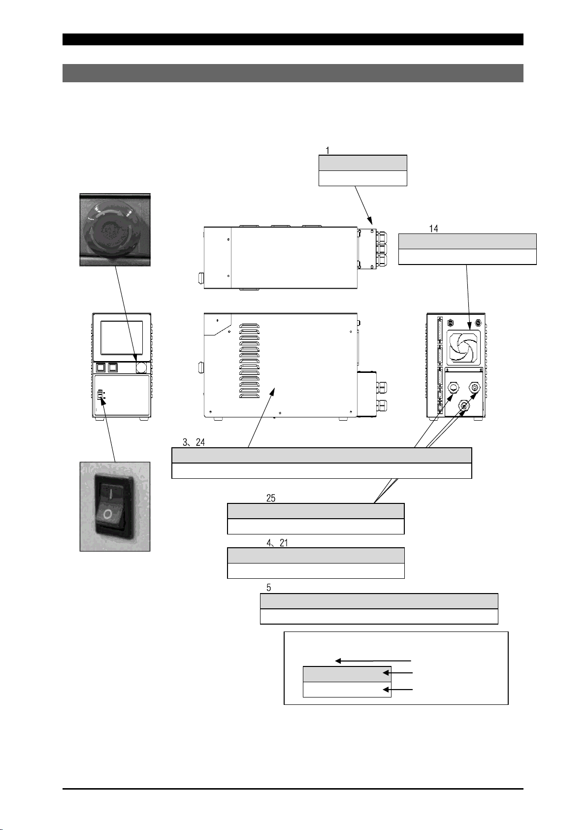
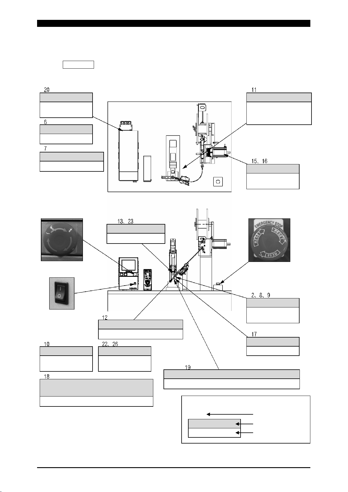
3. Operating Unit
(1) Front Panel··························································································· 3-1
4. Explanation of Screens
(1) Screen Structure ···················································································· 4-1
(2) Menu Screen························································································· 4-3
(3) Monitor Screen ······················································································ 4-5
(4) Envelope Screen····················································································4-10
(5) Basic Setting Screen···············································································4-15
(6) Switch Select Screen ··············································································4-17
(7) Initialize Memory Screen··········································································4-21
(8) External I/O Setting Screen ······································································4-22
(9) Welding Condition Setting Screen······························································4-23
(10) Schedule Setting Screen··········································································4-27
(11) Monitor Select Screen ·············································································4-30
(12) Upper/Lower Limit Set Screen···································································4-32
(13) SCH Copy Screen ··················································································4-33
(14) External I/O Check Screen ·······································································4-36
(15) Count Setting Screen ··············································································4-39
(16) Error History Screen ···············································································4-40
(17) Password Setting Screen ·········································································4-41
(18) Maintenance Screen ···············································································4-42
(19) Set Values of Each Screen at Delivery from the Factory··································4-43
5. Welding
(1) Pre-Start Inspection ················································································ 5-1
(2) Turning on the Power Supply ···································································· 5-2
(3) Basic Function Setting············································································· 5-3
(3) -1. Common detail item setting ······················································· 5-4
(4) Welding Condition Setting ········································································ 5-5
(4) -1. Registering the welding conditions ·············································· 5-5

MAWA-050A
Contents
iii
(4) -2. Welding current pulse modulation setting ····································· 5-6
(4) -3. Welding condition copy ····························································· 5-7
(5) Monitor Function Setting ·········································································· 5-8
(5) -1. Monitor item setting ································································· 5-8
(5) -2. Upper/lower limit value setting···················································· 5-9
(6) Touch Start ···························································································5-10
(6) -1. Overview ·············································································· 5-10
(6) -2. Operations ············································································ 5-10
(6) -2-1. Normal mode ···································································5-11
(6) -2-2. Auto mode ······································································ 5-13
(6) -2-3. Fine weld mode ······························································· 5-15
(6) -3. Adjustment············································································ 5-17
(6) -4. Start using an external input/output signal ··································· 5-17
(7) Preparation for Starting Welding ································································5-18
(8) Checking and Registering the Envelope Waveform Data·································5-19
(9) Shutting off the Power Supply ···································································5-20
6. Timing Chart
(1) Touch Start (when the normal mode is set)··················································· 6-1
(2) Touch Start (when the auto mode is set) ······················································ 6-3
(3) Touch Start (when the fine weld mode is set) ················································ 6-5
(4) Touch Start (when the customer-prepared motor head is used) ························ 6-7
(5) Touch Start (at occurrence of LOST)··························································· 6-9
(6) Touch Start (air type welding head) ····························································6-11
(7) Torch Changeover ··················································································6-12
(8) Schedule Changeover ·············································································6-13
(9) Option Input/Output Signals······································································6-14
(10) Condition No. and SCH Select Terminals·····················································6-16
7. External Communication Function
(1) Overview ······························································································ 7-1
(2) Data Transfer ························································································ 7-1
(3) Configuration························································································· 7-2
(4) Protocol ······························································································· 7-4
(5) Data Code Table ···················································································· 7-8
8. Troubleshooting
(1) Error Screen ························································································· 8-1
(2) Error Messages ····················································································· 8-2
(3) Error other than Above ············································································ 8-5
(4) Check Items when LOST Error Has Occurred··············································· 8-5
9. Maintenance
(1) Pre-Start Inspection ················································································ 9-1
(1) -1. Cable inspection······································································ 9-1
(1) -2. Torch inspection ······································································ 9-1
(1) -3. Argon gas inspection································································ 9-1
(2) Periodic Maintenance·············································································· 9-3
(2) -1. Monthly maintenance ······························································· 9-3
(2) -1-1. Cleaning the cooling fan filter··············································· 9-3

MAWA-050A
Notification of Risk Information
1
Notification of Risk Information
This “Notification of Risk Information” is intended to notify the risk or others related to this machine
(Ordinance on Industrial Safety and Health, Article 24-13) so as to promote the execution of risk
assessment (Industrial Safety and Health Act, Article 28-2) on the enterprise side for prevention of
labor disasters.
The risk map and residual risk table in this chapter include the matters to be described which are
specified in the guide (Notification No.132 of the Ministry of Health, Labor and Welfare issued in 2012)
related to the promotion of notice of the risk or others on the machine by the transferor of the machine.
This chapter is a part of the operation manual. Accordingly, do not operate the machine with an
understanding of only this chapter. Be sure to read through all the operation manual with a good
understanding of its contents before operating the machine.
In this “Notification of Risk Information” and the operation manual, “Injury Levels” are classified
according to the following definitions.
WARNING This indicates the existence of potential hazard which, if not avoided, may
result in death or serious injury of a personal.
CAUTION This indicates the existence of potential hazard which, if not avoided, may
result in a less serious injury of a personal.
Also, the Ministry of Health, Labor and Welfare in Japan revealed that “weld fumes” may cause
worker’s health problems such as neurological disorder. When using this product, wear a
dust-proof mask and perform ventilation in the workshop to prevent the occurrence of health
problems.

MAWA-050A
Notification of Risk Information
2
(1) Responsibility for Overall Management
(1) -1. Observance of laws, regulations and safety standard related to the
pulse TIG welding machine
When selecting an installation place of the pulse TIG welding machine, performing the
power supply work on the input side, handling and taking charge of high-pressure gas, and
taking charge of products after welding, and disposing wastes, please observe the laws,
regulations and safety standard of your company.
(1) -2. Execution of safety and health education
For the operator of the pulse TIG welding machine, give a special education of arc welding.
(Labor Safety and Health Regulations, Article 36)
In particular, execute an education and training about the following items.
Structure of the arc welding machine
How to handle the arc welding machine
Performance and handling of the light-shielding protector
Measures to be taken in an emergency
Prohibition of using the machine for other purposes than welding
(1) -3. Clothes for operations
For executing welding operations, put on clothes with long sleeves, foot covers, leather
protective globes, and other protectors such as apron. If scattered wastes (spatters) are
directly applied to the skin, this will result in a burn.
In accordance with the contents of each operation, put on an appropriate protector such as
safety cap, protective glasses and dust-proof mask.
Select each protector based on the safety standard for each operation.
(2) Prohibition of Disassembly, Repair and Modification of
the Welding Power Supply
A high voltage is applied to the inside of the welding power supply. Even after the supply power to
the welding power supply is shut off, a high voltage status is kept for a certain time. If the case of
the welding power supply is removed, this may result in a serious accident. Do not operate the
machine in the status where the terminal cover on the rear side of the welding power supply is
removed.

MAWA-050A
Notification of Risk Information
3
(3) Map of Residual Risks
For the details of various residual risks, refer to “(4) Table of Residual Risks.”
(3) -1. Map of residual risks of the welding power supply unit
Terminal cover
- Collapse
Welding power supply unit and welding power supply inside
- Electric shock
Input terminal and output terminal
- Electric shock
Input cable and connection cable
- Electric shock
Output cable (torch cable and grounding cable)
- Electric shock
Terminal cover
- Collapse
Emergency stop button
Main power switch
Welding power supply fan
- Rolling-in
Residual risk No.
Source of danger
Result of the source of
danger
1
Explanation of the map (example)

MAWA-050A
Notification of Risk Information
4
(3) -2. Map of residual risks of the standard system
(Welding power supply + Torch + Torch driving unit + Wire supply unit)
Remarks
This is supposed on the case where the standard welding machine is incorporated.
Execute risk assessment by using the customer’s actual specification.
Argon gas
- Poisoning
- Suffocation
Gas cylinder
- Collapse
Gas flow rate adjuster
- Breakage
Dust and argon gas
- Poisoning
- Suffocation
- Respiratory trouble
Wire supply unit
- Rolling-in
- Fire
Emergency stop button
Main power switch
Emergency stop button
Electrode and torch
- Electric shock
Gas generated from workpiece
- Respiratory trouble
Combustible
- Fire
- Explosion
Dust
- Fire
- Respiratory
Electromagnetic wave from the vicinity of
the welding power supply and torch
- Effect on the medical devices in the body
Arc light
- Optic trouble
- Burn
Welding jig
- Electric shock
Workpiece and electrode immediately after welding
- Burn
1
Explanation of the map (example)
- Collapse
Terminal cover
Residual risk No.
Source of danger
Result of the source of
danger

MAWA-050A
Notification of Risk Information
5
(4) Table of Residual Risks
For concrete positions of residual risks, refer to “(3) Map of Residual Risks.”
(4) -1. Installation
1 WARNING Transporting the welding power supply
[Source of risk] Terminal cover
[Contents of risk] If the welding power supply is transported by holding such a
projection as the terminal cover, the foot may be collapsed if it is
fallen down.
[Protective measure] When transporting the welding power supply by holding it with
hands, hold its bottom.
2 WARNING Installing the welding power supply
[Source of risk] Arc light
[Contents of risk]
In the pulse TIG welding machine, strong arc light will be scattered
at welding. If this arc light is caught by eyes, the eyes may be
inflamed.
[Protective measure] Install a light-shielding partition or light-shielding curtain around
the welding machine to mark off the welding work place so that arc
light may not be applied to the human eyes directly. (Ordinance
on Industrial Safety and Hygiene, Article 325)
3 WARNING Electric wiring
[Source of risk] Welding power supply unit
[Contents of risk] Unless the specified primary supply voltage and Class D
grounding work are omitted, an electric shock may be caused by
electric leakage or by high voltage due to mis-operation.
[Protective measure] Execute the primary power supply work and grounding work
according to the electric connection diagram. Connect the
welding power supply to the ground independently.

MAWA-050A
Notification of Risk Information
6
4 WARNING Electric wiring
[Source of risk] Input cable and input/output signal cable
[Contents of risk] If the cover is deteriorated or damaged, the cable is directly
touched, or a metallic part touched with the cable is touched, an
electric shock may be caused.
[Protective measure]
Do not use a deteriorated or damaged cable or plug. Put a cable
cover on the moving part or part touched with the human body so
that the input cable or input/output signal cable may not be
damaged.
5 WARNING Electric wiring
[Source of risk] Output cable (torch cable and grounding cable)
[Contents of risk] A large current flows and a high voltage of about 10 kV is applied
at a start of welding. If a cable with an insufficient capacity or a
cable with a low electric strength is used, a fire or electric shock
may be caused.
[Protective measure] Use the dedicated torch cable or grounding cable dedicate as the
output cable.
Fix the cable connecting part securely. Do not extend torch-side
cable and workpiece-side cable unnecessarily. The cable length
should be 10 m or less.
6 WARNING Gas piping
[Source of risk] Gas cylinder
[Contents of risk] If the gas cylinder is fallen down, the foot may be collapsed.
[Protective measure] Fix the gas cylinder securely on the gas cylinder stand or a
structure such as a wall or pillar.
7 WARNING Gas piping
[Source of risk] Gas flow rate adjuster
[Contents of risk] If an inappropriate gas flow rate adjuster is used for the gas
cylinder, explosion may be caused.
[Protective measure] Entrust the specialist with the gas piping work.

MAWA-050A
Notification of Risk Information
7
(4) -2. Machine operation
8 WARNING Welding
[Source of risk] Arc light
[Contents of risk] If arc light is directly seen, the eyes may be inflamed.
[Protective measure] Before performing welding operations, put on light-shielding
glasses or protective mask with light-shielding level No.9 or more.
To monitor welding, put on protective glasses with light-shielding
level No.9 or more or perform monitoring through a light-shielding
curtain.
Do not allow any person thoughtlessly to enter an area around the
welding machine and welding operation place.
9 WARNING Welding
[Source of risk] Arc light
[Contents of risk] If arc light is directly applied to the skin, the skin may get burnt.
[Protective measure] Before performing welding operations, put on protectors such as
the leather protective glasses for welding, clothes with long
sleeves, foot cover, and leather apron.
Do not allow any person thoughtlessly to enter an area around the
welding machine and welding operation place.
10 WARNING Welding
[Source of risk] Combustibles
[Contents of risk] If the waste (spatter) to be generated at welding is applied to any
combustible, it may catch fire, causing a fire or explosion.
[Protective measure] Do not perform welding near combustible gas.
Do not put any combustible around the welding operation place.
If the waste cannot be removed, put an incombustible cover on it.
Install a fire extinguisher in the welding operation place so that
even if a fire occurs, it may be extinguished immediately. A fire
extinguisher suitable for each target material must be selected for
use. Fire extinguishers are classified into a type for common fire,
type for oil fire, type for electric fire, and type for special fire
(metals, etc.). Prepare a fire extinguisher suitable for a
presupposed fire.

MAWA-050A
Notification of Risk Information
8
11 WARNING Welding
[Source of risk] Dust and argon gas
[Contents of risk] If the area is filled with dust and argon gas, the human body may
be badly affected.
[Protective measure] Perform ventilation around the welding operation place and the
whole factory at all times. Install sealed-up equipment, local
exhaust device, etc. and put on a gas mask or dust-
proof mask as
required.
12 WARNING Welding
[Source of risk] Gas generated from workpieces
[Contents of risk] After a covered steel plate is welded, the human body may be
affected by the generated gas.
[Protective measure] Perform ventilation around the welding operation place and the
whole factory at all times.
Install sealed-up equipment, local exhaust device, etc. and put on
a gas mask or dust-proof mask as required.
13 WARNING Welding
[Source of risk] Electrode and torch
[Contents of risk] At a start of arc discharge, a high voltage will be generated
between the electrode at the end of the torch and a workpiece. If
a person touches or approaches the electrode, an electric shock
may occur.
[Protective measure] Do not touch or approach the electrode portion during welding
operations.
Do not perform welding by holding the torch with hands.
14 CAUTION At all times
[Source of risk] Welding power supply cooling fan
[Contents of risk] If fingers or hairs are rolled into the welding power supply cooling
fan, this may result in an injury.
[Protective measure] Do not cause fingers and hairs to approach the fan that is rotated.

MAWA-050A
Notification of Risk Information
9
15 CAUTION At all times
[Source of risk] Rotary part of the wire supply unit
[Contents of risk] If hands, fingers, hairs or clothes are brought near the rotary part
of the wire supply unit, they may be rolled into it.
[Protective measure] While the power supply of the welding mach
ine is ON, do not bring
hands, fingers, hairs, clothes, etc. close to the rotary part.
16 CAUTION At all times
[Source of risk] Arc discharge of the wire supply unit
[Contents of risk] If the wire supply unit and a workpiece are electrically connected,
a high voltage may be applied through the wire, thereby causing
an arc discharge and a fire in an unexpected place.
[Protective measure] Perform insulation between the wire and the workpiece.
17 CAUTION Welding
[Source of risk] Welding jig
[Contents of risk] Electrification is performed neat the welding jig. If a person
touches such a place, an electric shock may occur.
[Protective measure] Perform grounding so as not to allow a workpiece or the welding
jig which is electrically connected with a workpiece to be an
electrified part.
During welding operations or just after welding operations, do not
touch the welding jig and area around the welding jig.
18 CAUTION Welding
[Source of risk] Electromagnetic wage from the welding power supply and torch
[Contents of risk]
In the case of a person using an electronic medical device such as
pace maker and germ eliminating device, the operation of an
electronic medical device may be affected by the electromagnetic
wave generated during arc discharge.
[Protective measure] Those who use any electronic medical device must not approach
around the welding machine or welding operation place without a
doctor’s permission.
If they feel unwell or are out of order, leave the place at once.

MAWA-050A
Notification of Risk Information
10
19 CAUTION Tak i n g out a workpiece
[Source of risk] Workpiece and electrode immediately after welding
[Contents of risk] Immediately after welding, the workpiece and electrode are still
hot. If the welded workpiece is touched with a bare hand or the
electrode is touched in taking out a workpiece, this may result in a
burn.
[Protective measure] Put on leather gloves when handling a workpiece.

MAWA-050A
Notification of Risk Information
11
(4) -3. Maintenance
20 WARNING Gas piping
[Source of risk] Argon gas
[Contents of risk] In case the argon gas piping work i
s inappropriate, a gas leak may
occur. If the welding operation place is filled with argon gas, the
human body may be affected badly.
[Protective measure] After replacement of a gas cylinder, consult with a gas piping
specialist or gas supply company abo
ut the gas pressure adjusting
operation.
21 WARNING Power inspecting
[Source of risk] Primary power piping
[Contents of risk] When inspecting the primary power wire on the factory side, an
electric shock may be caused by touching the charged part by
mistake.
[Protective measure] Before performing inspection operations, stop the electric power
supply and turn off the source power supply on the factory side.
Put a notice to notify “Under inspection” to the other operators.
22 WARNING Workshop cleaning
[Source of risk] Dust
[Contents of risk]
If dust is inhaled, the human body may be affected. And if dust is
accumulated, a fire may occur.
[Protective measure] Perform cleaning periodically around the welding operation place
and workshop.
Perform c
leaning by using a method that does not scatter dust, for
example, by using a vacuum cleaner or washing with water.
When dust is scattered, put on a dust-proof mask.

MAWA-050A
Notification of Risk Information
12
23 WARNING Electrode replacement
[Source of risk] Electrode
[Contents of risk] If another worker operates the welding power supply by mistake,
this may cause an electric shock due to a high voltage to the
worker who replaces the electrode. In case a voltage is left by
charged electrode, an electric shock may occur.
[Protective measure] Before performing electrode replacing operations, turn off the
welding power supply. For other workers, “Under electrode
replacement” should be indicated.
Short-circuit the electrode with the grounding side to discharge a
charged status and then start electrode replacing operations.
24 WARNING Welding power supply maintenance
[Source of risk] Inside of the welding power supply
[Contents of risk] If the case is removed and the internal high-voltage portion is
touched immediately after the power sup
ply is turned on or off, this
may result in a death. Even after the power supply is turned off,
the capacitor remains charged for a certain time.
[Protective measure] Do not open the case of the welding power supply. If a welding
power supply trouble occurs, make contact with us or the
distributor.
25 WARNING Welding power supply removal
[Source of risk] Input terminal and output terminal
[Contents of risk]
If the primary supply voltage is supplied to the input terminal or the
output terminal remains charged when the welding power supply
is removed, this may cause an electric shock.
[Protective measure] Before removing the welding power supply, shut off the power to
the welding power supply and short-circuit the electrode with the
grounding side to discharge the electricity charged in the output
terminal. Then, remove the output terminal.

MAWA-050A
Notification of Risk Information
13
(4) -4. Scrapping
26 WARNING Dust scrapping
[Source of risk] Dust
[Contents of risk] If dust is inhaled, the human body may be badly affected.
[Protective measure] Classify collected dust according to materials and keep it in a can
with a cover so that it may not be scattered. Scrap it as industrial
waste. Do not scrap it like general waste.

MAWA-050A
Notification of Risk Information
14
(5) On Disposal
This product incorporates parts containing gallium arsenide (GaAs). At the time of disposal, separate
it from general industrial waste or domestic waste and carry out the disposal in accordance with
applicable laws and regulations.
(6) Warning Labels
A warning label is pasted on the welding power supply unit for safe use. The pasting place and
meaning of each label are as shown below.
Pasting place: Upper part of the terminal cover
Meaning: Danger of electric shock
注 意
CAUTION
CONNECT GROUNDING WIRE.
アース線を接続する事
注意
DO NOT OPEN COVER.
TOUCHING THE INSIDE
MAY CAUSE AN ELECTRIC SHOCK.
CAUTION
感電の恐れあり
カバーを開けるな
注 意
CAUTION
ROTATING!
DO NOT INSERT A ROD
OR OTHER FOREIGN OBJECTS.
回転物注意
指、物等を入れるな
P-00202-003
Pasting place: Front side of the upper part of the main unit
Meaning:
Caution for grounding
wire connection
Danger of electric
shock
Pay attention to rotary
materials such as fan
!
DO NOT OPEN。
PLEASE CONTACT MANUFACTURER
IN CASE OF MALFUNCTION。
ケースを開けないでください。
サービスマン以外は、
P-00065- 002
Pasting place: Rear side of the upper part of the main unit
Meaning: Danger of electric shock
Pasting place: Side surface of the terminal cover
Meaning: Danger of electric shock
(Only models subject to CCC)
Pasting place: Rear side of the upper part of the main unit
Meaning: Danger of electric shock
Danger of welding dust and fume
Danger of fire
Danger of arc light

MAWA-050A
1. Overview
1-1
1. Overview
(1) Features
Since this equipment is designed in a compact form, it can be moved and installed easily.
The equipment is provided with a welding current monitoring function to support the OK/NG
judgment of welding.
Stabilized welding quality is realized by constant-current control.
Noiseless performance and positioning of discharge can be achieved by the touch start function.
Each setting can be easily performed by using a menu selection system of the touch panel.

MAWA-050A
1. Overview
1-2
(2) Names of Parts
(2) -1. Front panel
The names of operating parts such as switches on the front panel are shown below. For the
function of each part, refer to “3. (1) Front Panel.”
Main power switch
Touch panel display
START button (with a green LED incorporated)
RESET button (with an orange LED incorporated)
Emergency stop button
Table of contents
Other Amada Power Supply manuals

Amada
Amada IP-100D User manual

Amada
Amada S-2200CA User manual

Amada
Amada HF2 User manual

Amada
Amada CL-P115A User manual

Amada
Amada IP-400B User manual

Amada
Amada IS-800CR User manual

Amada
Amada MD-A8000B-05 Series User manual

Amada
Amada 125ADP User manual

Amada
Amada UNIFLOW UF-R4000A User manual

Amada
Amada IP-500A User manual
Popular Power Supply manuals by other brands

B+K precision
B+K precision 1550 instruction manual

Pegasus Astro
Pegasus Astro Ultimate Powerbox operating instructions

Ultra Power
Ultra Power Touch UP120AC instruction manual

Meanwell
Meanwell DDR-120 Series installation manual

Cal Power
Cal Power ITech IT6860B Series user manual

I-Tech
I-Tech IT-M3900D Series user manual